EP0455542B1 - Geräuscharme Kreiselmotorpumpe für Flüssigkeiten - Google Patents
Geräuscharme Kreiselmotorpumpe für Flüssigkeiten Download PDFInfo
- Publication number
- EP0455542B1 EP0455542B1 EP91401098A EP91401098A EP0455542B1 EP 0455542 B1 EP0455542 B1 EP 0455542B1 EP 91401098 A EP91401098 A EP 91401098A EP 91401098 A EP91401098 A EP 91401098A EP 0455542 B1 EP0455542 B1 EP 0455542B1
- Authority
- EP
- European Patent Office
- Prior art keywords
- pump
- chamber
- centrifugal
- axial
- inverted
- Prior art date
- Legal status (The legal status is an assumption and is not a legal conclusion. Google has not performed a legal analysis and makes no representation as to the accuracy of the status listed.)
- Expired - Lifetime
Links
- 239000007788 liquid Substances 0.000 title claims description 35
- 230000002093 peripheral effect Effects 0.000 claims abstract description 9
- 235000001674 Agaricus brunnescens Nutrition 0.000 claims description 2
- 239000002184 metal Substances 0.000 claims description 2
- 229910001092 metal group alloy Inorganic materials 0.000 claims description 2
- 238000000465 moulding Methods 0.000 claims description 2
- 229920002994 synthetic fiber Polymers 0.000 claims description 2
- 238000010079 rubber tapping Methods 0.000 claims 1
- 208000028659 discharge Diseases 0.000 description 8
- 238000004519 manufacturing process Methods 0.000 description 2
- 238000001471 micro-filtration Methods 0.000 description 2
- 230000010349 pulsation Effects 0.000 description 2
- 238000004064 recycling Methods 0.000 description 2
- 239000002699 waste material Substances 0.000 description 2
- 230000015572 biosynthetic process Effects 0.000 description 1
- 125000004122 cyclic group Chemical group 0.000 description 1
- 238000005406 washing Methods 0.000 description 1
Images
Classifications
-
- F—MECHANICAL ENGINEERING; LIGHTING; HEATING; WEAPONS; BLASTING
- F04—POSITIVE - DISPLACEMENT MACHINES FOR LIQUIDS; PUMPS FOR LIQUIDS OR ELASTIC FLUIDS
- F04D—NON-POSITIVE-DISPLACEMENT PUMPS
- F04D29/00—Details, component parts, or accessories
- F04D29/66—Combating cavitation, whirls, noise, vibration or the like; Balancing
- F04D29/669—Combating cavitation, whirls, noise, vibration or the like; Balancing especially adapted for liquid pumps
-
- F—MECHANICAL ENGINEERING; LIGHTING; HEATING; WEAPONS; BLASTING
- F04—POSITIVE - DISPLACEMENT MACHINES FOR LIQUIDS; PUMPS FOR LIQUIDS OR ELASTIC FLUIDS
- F04D—NON-POSITIVE-DISPLACEMENT PUMPS
- F04D29/00—Details, component parts, or accessories
- F04D29/18—Rotors
- F04D29/22—Rotors specially for centrifugal pumps
- F04D29/2205—Conventional flow pattern
- F04D29/2216—Shape, geometry
-
- F—MECHANICAL ENGINEERING; LIGHTING; HEATING; WEAPONS; BLASTING
- F04—POSITIVE - DISPLACEMENT MACHINES FOR LIQUIDS; PUMPS FOR LIQUIDS OR ELASTIC FLUIDS
- F04D—NON-POSITIVE-DISPLACEMENT PUMPS
- F04D29/00—Details, component parts, or accessories
- F04D29/40—Casings; Connections of working fluid
- F04D29/42—Casings; Connections of working fluid for radial or helico-centrifugal pumps
- F04D29/44—Fluid-guiding means, e.g. diffusers
- F04D29/445—Fluid-guiding means, e.g. diffusers especially adapted for liquid pumps
Definitions
- the present invention relates to a silent liquid centrifugal motor pump.
- liquid centrifugal motor pumps include in their pump either a circular pump chamber having a concentric impeller and a deflector or liquid guide nozzle or a pump chamber with increasing dimensions in the form of a volute, such as for example that described in document GB-A-28 326, defined by a substantially circular chamber and an impeller mounted eccentrically in this chamber.
- These motor pumps are usually noisy in their operation. Their operating noises come mainly from those generated by liquid overpressures created by cyclic passages of the blades of their front wheel, either their liquid guide spout, or a salient angle of their volute-shaped pump chamber. This situation creates pulsations of pressure in the column of discharged liquid which not only makes the pump noisy, but downstream can generate noise wherever the liquid is transported under pressure.
- the present invention aims to avoid these drawbacks of known motor pumps, makes it possible to produce a liquid centrifugal motor pump, economical in its manufacture, efficient and silent in its operation.
- a silent liquid centrifugal motor pump having in its centrifugal pump a pump plate and a pump card defining a pump chamber in which an impeller rotates
- the pump chamber consists of two concentric chambers, namely a central revolution chamber, having an axial T-shaped section, called an impeller chamber, in which the impeller turns concentrically and an annular peripheral delivery chamber having an axial L-shaped section inverted with rounded angle and substantially wide constant, extending the impeller chamber radially then axially at the level of the arms of the T from its axial T-section.
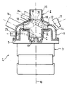
- a centrifugal liquid motor pump 1 illustrated schematically and partially in section comprises a centrifugal pump 2 and an electric drive motor 3.
- the centrifugal pump 2 comprises a pump plate 5, a pump casing 6 and an impeller 7 of a conventional type driven in rotation by a shaft represented diagrammatically by dashed lines 10 of the electric motor 3.
- the pump plate 5 and the pump casing 6 which are assembled and mounted coaxially with the shaft 10 of the motor 3 define a pump chamber 12.
- the pump housing 6 having substantially the shape of a cup of revolution comprises in its center, an axial tube 15 serving as a liquid inlet tube, and in its periphery, at least one tube 16 serving as a liquid outlet tube .
- the impeller 7 mounted on the shaft 10 of the motor 3 and rotating concentrically in the pump chamber 12 comprises spaced vanes 18, oriented from the center of this wheel towards the periphery, a lower flange 19 having the shape of a mushroom and an upper flange 20 having the shape of a funnel which define for the flow of the liquid, a common axial inlet 21, passages leading to the periphery, and lateral outlets 22 parallel to a plane perpendicular to the axis of rotation of the impeller 7.
- the pump chamber 12 consists of two concentric chambers, namely a central revolution chamber, having an axial T-shaped section, called the impeller chamber 13, in which the impeller 7 concentrically rotates and a peripheral discharge chamber 14 , annular having an inverted L-shaped axial section with rounded angle and substantially constant width, extending radially then axially the impeller chamber 13 at the arms of the T of its axial section in T.
- the constant width of the L of the axial section in L reversed from the discharge chamber 14 is predetermined substantially equal the dimensions of the lateral peripheral outlets 22 for liquid from the impeller 7.
- the liquid outlet pipe 16 formed in the pump housing 6 is in tangential communication with the delivery chamber 14 at the level of the large branch of the L of its axial section in inverted L and provided, in the example, with a inclined axis making an angle of approximately 65 ° with the axis of this pump housing 6.
- the impeller 7 sucks liquid through the inlet pipe 15 of the pump housing 6, its axial common inlet opening 21, in the impeller 7 and the impeller chamber 13, and discharges it through its lateral peripheral outlets 22, the discharge chamber 14 and the outlet pipe 16, towards the outside.
- the liquid entering the pump 2 is guided and channeled by the vanes 18 and the lower 19 and upper 20 flanges of these vanes of the impeller, calibrated by the lateral peripheral outlets 22 of this impeller 7 whose dimensions are, according to the invention, determined substantially equal to the constant width of the L of the axial section in inverted L of the discharge chamber 14 by this impeller 7 which rotates concentrically with the annular inlet of this chamber 14 without being subjected along this delivery chamber 14 to the tubing of the liquid outlet 16, neither to a variation in flow rate, nor to a change in pressure which generate in the flowing liquid, pulsations which make the pump 2 noisy as well as its circuit repression.
- the concentric characteristic between the impeller wheel 7 and the discharge chamber 14 which extends the impeller chamber 13 and the preset adjustment of the dimensions of the peripheral lateral outlets 22 of the impeller vanes 7 with the width of the L of the axial section in L reversed from the delivery chamber 14 allow a passage without turbulence of the liquid, of the impeller 7 in the delivery chamber 14, through the annular opening of this room 14, and thus reinforce the silent operation of the motor pump 1.
- the width of the L of the axial section in inverted L of the delivery chamber 14 which is substantially constant and equal to the dimensions of the lateral peripheral outlets 22 for liquid from the impeller 7 promotes permanent formation in this delivery chamber 14 during the operation of the motor pump 1, of a ring full of liquid, that is to say a ring of liquid without air pockets which create a fluctuation in flow and / or pressure of liquid, generating noise.
- the motor pump 1 illustrated comprises in its centrifugal pump 2, an inlet pipe for liquid 15 connected to a point of a lower part d '' a tank of this dishwasher, two lateral pipes of main outlets for liquid 16 and 17 with inclined axes making an angle of approximately 65 ° with the axis of the pump casing 6 in tangential communication with the discharge chamber 14 at the level of the large branch of the L of the inverted L-shaped axial section of this chamber and connected respectively to two upper and lower sprinkler reels of this dishwasher, a lateral outlet pipe in liquid bypass 24 with an inclined axis forming an angle Approximately 65 ° with the axis of the pump housing 6, in tangential communication with the delivery chamber 14 at the level of the small branch of the L of the axial section in L reversed from this chamber and connected to a system of microfiltration of waste in the liquid being recycled in this dishwasher, and a lateral tubing for taking the liquid pressure 25 with an inclined axis making an
- the pump plate 5 and the pump casing 6 are preferably made advantageously by molding a synthetic material, a metal or a metal alloy.
- motor pump 1 The structure of motor pump 1 is simple. The manufacture of the motor pump 1 is easy and economical.
Landscapes
- Engineering & Computer Science (AREA)
- Mechanical Engineering (AREA)
- General Engineering & Computer Science (AREA)
- Physics & Mathematics (AREA)
- Geometry (AREA)
- Structures Of Non-Positive Displacement Pumps (AREA)
- Exhaust Gas After Treatment (AREA)
Claims (5)
- Geräuscharme Flüssigkeits-Kreiselmotorpumpe, die in ihrer Kreiselpumpe (2) eine Pumpengrundplatte (5) und ein Pumpengehäuse (6) aufweist, die eine Pumpenkammer abgrenzen, in welcher sich ein Schaufelrad (7) dreht, dadurch gekennzeichnet, daß die Pumpenkammer (12) durch zwei konzentrische Kammern gebildet ist, nämlich durch eine rotationssymmetrische Mittelkammer mit T-förmigem Axialschnitt, die Schaufelradkammer (13) genannt wird und in der sich konzentrisch das Schaufelrad dreht, und eine ringförmige Umfangsförderkammer (14), die einen Axialschnitt in Form eines umgedrehten L mit abgerundeter Ecke sowie eine im wesentlichen konstante Breite aufweist und die die Schaufelradkammer (13) auf Höhe der Arme des T des T-förmigen Axialschnittes radial und dann axial verlängert.
- Motorpumpe nach Anspruch 1, mit einem Schaufelrad (7) in der Kreiselpumpe (2), das voneinander beabstandete Schaufeln (8) aufweist, die von der Mitte des Rades zum Umfang ausgerichtet sind, sowie einen pilzförmigen unteren Flansch (19) und einen trichterförmigen oberen Flansch (20), wodurch für das Strömen der Flüssigkeit ein gemeinsamer Axialeingang (21), zum Umfang führende Durchgänge sowie seitliche Ausgänge (22) gebildet sind, dadurch gekennzeichnet, daß die seitlichen Ausgänge (22) zu einer zur Rotationsachse des Schaufelrades (7) senkrechten Ebene parallel und mit Abmessungen ausgebildet sind, die im wesentlichen gleich der konstanten Breite des L der Förderkammer (14) mit dem Axialschnitt in Form eines umgedrehten L sind.
- Motorpumpe nach einem der Ansprüche 1 und 2, dadurch gekennzeichnet, daß das Pumpengehäuse (6) in der Kreiselpumpe (2) wenigstens ein axiales Eingangsrohr (15) sowie ein seitliches Ausgangsrohr (16) aufweist, das mit der Förderkammer (14) auf Höhe des großen Schenkels des L der Kammer mit dem Axialschnittes in Form eines umgedrehten L tangential in Verbindung steht und eine geneigte Achse aufweist, die mit der Achse des Pumpengehäuses (6) einen Winkel von ungefähr 65° einschließt.
- Motorpumpe nach Anspruch 3, dadurch gekennzeichnet, daß das Pumpengehäuse (6) in der Kreiselpumpe (2) ein axiales Eingangsrohr (15) sowie drei seitliche Ausgangsrohre (16, 17, 24) aufweist, deren geneigte Achsen mit der Achse des Pumpengehäuses einen Winkel von ungefähr 65° einschließen und von denen zwei (16, 17), die als Hauptausgänge dienen, mit der Förderkammer (14) auf Höhe des großen Schenkels des L der Kammer mit dem Axialschnitt in Form eines umgedrehten L tangential in Verbindung stehen und von denen eines (24), das als Abzweigausgang dient, mit der Förderkammer (14) auf Höhe des kleinen Schenkels des L der Kammer mit dem Axialschnitt in Form eines umgedrehten L tangential in Verbindung steht, und ein seitliches Rohr (25) zur Abnahme des Flüssigkeitsdrucks, dessen geneigte Achse mit der Achse des Pumpengehäuses (6) einen Winkel von ungefähr 90° einschließt und das mit der Förderkammer (14) auf Höhe des großen Schenkels des L der Kammer mit dem Axialschnitt in Form eines umgedrehten L tangential in Verbindung steht.
- Motorpumpe nach einem der Ansprüche 1 bis 4, dadurch gekennzeichnet, daß die Kreiselpumpe (2), die Pumpengrundplatte (5) und das Pumpengehäuse (6) vorzugsweise durch Formen eines synthetischen Materials, eines Metalls oder einer Metallegierung gebildet sind.
Applications Claiming Priority (2)
| Application Number | Priority Date | Filing Date | Title |
|---|---|---|---|
| FR9005639A FR2661717B1 (fr) | 1990-05-04 | 1990-05-04 | Motopompe centrifuge silencieuse a liquide. |
| FR9005639 | 1990-05-04 |
Publications (2)
| Publication Number | Publication Date |
|---|---|
| EP0455542A1 EP0455542A1 (de) | 1991-11-06 |
| EP0455542B1 true EP0455542B1 (de) | 1995-02-15 |
Family
ID=9396333
Family Applications (1)
| Application Number | Title | Priority Date | Filing Date |
|---|---|---|---|
| EP91401098A Expired - Lifetime EP0455542B1 (de) | 1990-05-04 | 1991-04-25 | Geräuscharme Kreiselmotorpumpe für Flüssigkeiten |
Country Status (5)
| Country | Link |
|---|---|
| EP (1) | EP0455542B1 (de) |
| AT (1) | ATE118601T1 (de) |
| DE (1) | DE69107330T2 (de) |
| ES (1) | ES2067883T3 (de) |
| FR (1) | FR2661717B1 (de) |
Families Citing this family (2)
| Publication number | Priority date | Publication date | Assignee | Title |
|---|---|---|---|---|
| EP1375924B1 (de) * | 2002-06-22 | 2010-01-06 | GEA Tuchenhagen GmbH | Leitvorrichtung für ein Gehäuse einer Kreiselpumpe |
| FR2974866B1 (fr) * | 2011-05-03 | 2013-05-10 | Francois Gerlier | Pompe de circulation d'electrolyte pour engin marin |
Family Cites Families (5)
| Publication number | Priority date | Publication date | Assignee | Title |
|---|---|---|---|---|
| GB283261A (de) * | 1900-01-01 | |||
| GB191128326A (en) * | 1911-12-16 | 1912-12-16 | John Taylor | Improvements in Centrifugal Pumps. |
| JPS63109300A (ja) * | 1986-10-24 | 1988-05-13 | Matsushita Electric Ind Co Ltd | 電動送風機 |
| SU1413292A1 (ru) * | 1987-02-16 | 1988-07-30 | Сумский филиал Харьковского политехнического института им.В.И.Ленина | Корпус свободновихревого насоса |
| EP0298191B1 (de) * | 1987-07-06 | 1992-05-20 | Rockwell International Corporation | Zylindrischer Pumpenmehrfachauslass-Sammler |
-
1990
- 1990-05-04 FR FR9005639A patent/FR2661717B1/fr not_active Expired - Fee Related
-
1991
- 1991-04-25 ES ES91401098T patent/ES2067883T3/es not_active Expired - Lifetime
- 1991-04-25 EP EP91401098A patent/EP0455542B1/de not_active Expired - Lifetime
- 1991-04-25 DE DE69107330T patent/DE69107330T2/de not_active Expired - Fee Related
- 1991-04-25 AT AT91401098T patent/ATE118601T1/de not_active IP Right Cessation
Also Published As
| Publication number | Publication date |
|---|---|
| FR2661717A1 (fr) | 1991-11-08 |
| DE69107330T2 (de) | 1995-06-14 |
| DE69107330D1 (de) | 1995-03-23 |
| FR2661717B1 (fr) | 1992-07-03 |
| ES2067883T3 (es) | 1995-04-01 |
| EP0455542A1 (de) | 1991-11-06 |
| ATE118601T1 (de) | 1995-03-15 |
Similar Documents
| Publication | Publication Date | Title |
|---|---|---|
| US5330475A (en) | Modular fuel sender for motor vehicle | |
| SE457552B (sv) | Sidokanalpump | |
| US3444817A (en) | Fluid pump | |
| EP1923572A2 (de) | Elektrisches Gebläse für ein elektrisches Reinigungsgerät | |
| JPH06280777A (ja) | 逆流防止口を有する燃料ポンプ | |
| JPH08232884A (ja) | 全周流型ポンプ群及びその製造方法 | |
| FR2517381A1 (fr) | Roue a aubes radiale pour pompes centrifuges | |
| EP0455542A1 (de) | Geräuscharme Kreiselmotorpumpe für Flüssigkeiten | |
| US5375975A (en) | Fuel pump pre-swirl inlet channel | |
| KR101425826B1 (ko) | 회전 및 수렴 허브를 갖는 임펠러 및 디퓨저 | |
| US5364238A (en) | Divergent inlet for an automotive fuel pump | |
| JP3833581B2 (ja) | 遠心式送風機 | |
| US5509778A (en) | Fuel pump for motor vehicle | |
| JPH06207592A (ja) | ポンプハウジング装置 | |
| CN1063529C (zh) | 离心泵 | |
| GB2259113A (en) | Pump having spiral blades | |
| CN207660844U (zh) | 一种离心泵 | |
| CN109973424B (zh) | 用于清洗机的水泵叶轮及其应用 | |
| FR2565635A1 (fr) | Turbine de pompe | |
| CN109630425A (zh) | 高效高压大流量无堵转模块化多功能漩涡泵 | |
| SE501165C2 (sv) | Pumphus för virvelströmspump | |
| US3790300A (en) | Multi-function centrifugal blower unit | |
| CN219083208U (zh) | 一种吸油烟机 | |
| NO773496L (no) | Sentrifugalpumpe. | |
| GB2082688A (en) | Axial fluid flow machines |
Legal Events
| Date | Code | Title | Description |
|---|---|---|---|
| PUAI | Public reference made under article 153(3) epc to a published international application that has entered the european phase |
Free format text: ORIGINAL CODE: 0009012 |
|
| AK | Designated contracting states |
Kind code of ref document: A1 Designated state(s): AT DE ES FR |
|
| 17P | Request for examination filed |
Effective date: 19911123 |
|
| 17Q | First examination report despatched |
Effective date: 19930622 |
|
| GRAA | (expected) grant |
Free format text: ORIGINAL CODE: 0009210 |
|
| AK | Designated contracting states |
Kind code of ref document: B1 Designated state(s): AT DE ES FR |
|
| REF | Corresponds to: |
Ref document number: 118601 Country of ref document: AT Date of ref document: 19950315 Kind code of ref document: T |
|
| REF | Corresponds to: |
Ref document number: 69107330 Country of ref document: DE Date of ref document: 19950323 |
|
| REG | Reference to a national code |
Ref country code: ES Ref legal event code: FG2A Ref document number: 2067883 Country of ref document: ES Kind code of ref document: T3 |
|
| PLBE | No opposition filed within time limit |
Free format text: ORIGINAL CODE: 0009261 |
|
| STAA | Information on the status of an ep patent application or granted ep patent |
Free format text: STATUS: NO OPPOSITION FILED WITHIN TIME LIMIT |
|
| 26N | No opposition filed | ||
| PGFP | Annual fee paid to national office [announced via postgrant information from national office to epo] |
Ref country code: AT Payment date: 19990429 Year of fee payment: 9 |
|
| PG25 | Lapsed in a contracting state [announced via postgrant information from national office to epo] |
Ref country code: AT Free format text: LAPSE BECAUSE OF NON-PAYMENT OF DUE FEES Effective date: 20000425 |
|
| REG | Reference to a national code |
Ref country code: FR Ref legal event code: TP |
|
| PGFP | Annual fee paid to national office [announced via postgrant information from national office to epo] |
Ref country code: DE Payment date: 20070511 Year of fee payment: 17 |
|
| REG | Reference to a national code |
Ref country code: ES Ref legal event code: PC2A |
|
| PG25 | Lapsed in a contracting state [announced via postgrant information from national office to epo] |
Ref country code: DE Free format text: LAPSE BECAUSE OF NON-PAYMENT OF DUE FEES Effective date: 20081101 |
|
| PGFP | Annual fee paid to national office [announced via postgrant information from national office to epo] |
Ref country code: ES Payment date: 20090427 Year of fee payment: 19 |
|
| PGFP | Annual fee paid to national office [announced via postgrant information from national office to epo] |
Ref country code: FR Payment date: 20090430 Year of fee payment: 19 |
|
| REG | Reference to a national code |
Ref country code: FR Ref legal event code: ST Effective date: 20101230 |
|
| REG | Reference to a national code |
Ref country code: ES Ref legal event code: FD2A Effective date: 20110708 |
|
| PG25 | Lapsed in a contracting state [announced via postgrant information from national office to epo] |
Ref country code: ES Free format text: LAPSE BECAUSE OF NON-PAYMENT OF DUE FEES Effective date: 20110628 |
|
| PG25 | Lapsed in a contracting state [announced via postgrant information from national office to epo] |
Ref country code: ES Free format text: LAPSE BECAUSE OF NON-PAYMENT OF DUE FEES Effective date: 20100426 |
|
| PG25 | Lapsed in a contracting state [announced via postgrant information from national office to epo] |
Ref country code: FR Free format text: LAPSE BECAUSE OF NON-PAYMENT OF DUE FEES Effective date: 20100430 |