EP0455543A1 - Vorrichtung zur Ausrichtung einer Reflektorantenne - Google Patents
Vorrichtung zur Ausrichtung einer Reflektorantenne Download PDFInfo
- Publication number
- EP0455543A1 EP0455543A1 EP91401103A EP91401103A EP0455543A1 EP 0455543 A1 EP0455543 A1 EP 0455543A1 EP 91401103 A EP91401103 A EP 91401103A EP 91401103 A EP91401103 A EP 91401103A EP 0455543 A1 EP0455543 A1 EP 0455543A1
- Authority
- EP
- European Patent Office
- Prior art keywords
- axis
- reflector
- lever
- support
- arm
- Prior art date
- Legal status (The legal status is an assumption and is not a legal conclusion. Google has not performed a legal analysis and makes no representation as to the accuracy of the status listed.)
- Granted
Links
- 238000005096 rolling process Methods 0.000 claims description 2
- 238000005461 lubrication Methods 0.000 description 3
- 239000003638 chemical reducing agent Substances 0.000 description 2
- 238000010586 diagram Methods 0.000 description 2
- 238000006073 displacement reaction Methods 0.000 description 2
- 239000010749 BS 2869 Class C1 Substances 0.000 description 1
- 230000009286 beneficial effect Effects 0.000 description 1
- 230000007547 defect Effects 0.000 description 1
- 230000001627 detrimental effect Effects 0.000 description 1
- 230000007717 exclusion Effects 0.000 description 1
- 238000009434 installation Methods 0.000 description 1
- 230000002427 irreversible effect Effects 0.000 description 1
- 239000013589 supplement Substances 0.000 description 1
Images


Classifications
-
- H—ELECTRICITY
- H01—ELECTRIC ELEMENTS
- H01Q—ANTENNAS, i.e. RADIO AERIALS
- H01Q1/00—Details of, or arrangements associated with, antennas
- H01Q1/12—Supports; Mounting means
- H01Q1/125—Means for positioning
-
- H—ELECTRICITY
- H01—ELECTRIC ELEMENTS
- H01Q—ANTENNAS, i.e. RADIO AERIALS
- H01Q1/00—Details of, or arrangements associated with, antennas
- H01Q1/27—Adaptation for use in or on movable bodies
- H01Q1/28—Adaptation for use in or on aircraft, missiles, satellites, or balloons
- H01Q1/288—Satellite antennas
Definitions
- the subject of the invention is a device for pointing the reflector, generally parabolic, of an antenna, making it possible to modify the orientation of the reflector by giving it a movement which can be regarded as resulting from the composition of two rotational movements around axes orthogonal to each other, orthogonal to the main axis of the reflector and passing through the focus of the reflector.
- paraboid reflector should be taken in a broad sense and as covering not only reflectors having a shape strictly in the form of a paraboid, but those deviating little from this shape, and as covering as well reflectors having a symmetry of revolution than those formed by an eccentric dish of paraboloid.
- the invention finds particularly important applications in the pointing of satellite antennas, where it is often necessary to supplement a rough pointing carried out by controlling the attitude of the satellite with a fine pointing, in a field corresponding to a cone whose angle at the top hardly exceeds ten degrees.
- the pointing of an antenna by rotation of its reflector around the hearth seems a priori easy to achieve by means of very diverse nature.
- the present invention aims in particular to eliminate these defects.
- the invention proposes in particular a device for pointing the antenna reflector by rotation relative to a support, comprising: an arm fixed to the reflector and carried by the support by means of a seal allowing it to rotate around two orthogonal axes passing through the focus of the reflector and perpendicular to an axis of the reflector; and arm drive means having a first rotary motor of axis directed towards the focus, carried by the support and driving a first lever and a second rotary motor of axis directed towards the focus, carried by the first lever and driving a second lever connected to the arm by a rod rotating on the second lever around an axis directed towards the hearth.
- the composition of the two rotational movements around axes contributing to the focus results in a change of orientation around the focus.
- the seal is advantageously provided so as to have only rolling links, with the exclusion of sliding links, when the conditions of use restrict the possibilities of lubrication, which is the case on a satellite.
- the seal may in particular be constituted by a gimbal, the intermediate frame of which is hollowed out so as to leave the necessary space for the source or the receiver placed at the focus of the reflector and fixed relative to the support.
- the articulation bearing of the link on the second lever must tolerate slight angular deflections of the axis of rotation: in practice, the slight play that a bearing presents will often be sufficient. Otherwise, flexible blade mounting can be used.
- the radii of the circles traversed by the axis of the second motor around the axis of the first and by the axis of the bearing around the axis of the second motor are generally chosen so that the angles at the top of the corresponding cones are each equal to half the angle at the top of the aiming cone, centered on the axis of the first engine.
- the two levers will then have substantially the same length and will be approximately the same distance from the focal point, which makes it possible to give the antenna all the possible pointing within a cone. However, when it is possible to admit a prohibited zone in the center of the cone, it is possible to give the arms slightly different lengths.
- the device according to the invention has many advantages.
- the reduction is very important, the angle of which the reflector rotates being much less (often of an order of magnitude) than the angle of which one or the other of the two motors rotates.
- the motors themselves can be made up of irreversible electric motors because they are fitted with a high ratio reducer often exceeding 100, which increases rigidity and prevents drifts.
- the motors can be placed in the immediate vicinity of the support, which is advantageous in the case of installation in space since the thermal operating conditions are improved.
- the device shown in FIG. 1 is intended to orient a reflector 10, in the form of a cap of an eccentric paraboloid with a main axis 11, relative to a support 12 formed by the body of a satellite, by rotation around the focal point F , where is a source (not shown) such as a cornet.
- the device comprises an arm 13, rigid during the implementation of the device, but which can be made up of two parts connected by a lockable articulation 14, in order to allow the folding of the arm and the application of the reflector 10 against the support 12 when launching the satellite.
- the arm 13 is carried by the support 12 by means of a seal allowing it to take any orientation in a cone centered on the focal point F and whose apex angle 2 ⁇ corresponds to the necessary pointing range. In practice, the half angle at the top will hardly exceed 10 degrees. An angle of 12 degrees has been planned for a currently planned telecommunications satellite.
- the end of the arm 13 opposite the joint 15 is fixed to the reflector 10.
- the drive means of the arm 13 are interposed between the support 12 and an intermediate point of the arm.
- the location of these means and their constitution are such that they do not obscure the antenna lobe.
- they are carried by a console 18 fixed to the support and they drive a rod 20 fixed to the arm rigidly, between the hearth F and the end fixed to the reflector.
- a first rotary motor 22, the axis of which is directed towards the focal point, can be provided to coincide with the main axis of the paraboloid when the reflector is in its middle position, and comprises a stator fixed to the console 18 and a bearing rotor a first lever 24.
- This first lever 24 carries the stator of a second electric motor 26 of axis also directed towards the hearth F and whose rotor carries a second lever 28.
- the latter is connected to the link 20 by means 30 allowing a 360 ° rotation around an axis directed towards the focal point F and slight tilting movements.
- the means 30 can be constituted by a bearing each time lubrication is excluded. Many bearings indeed tolerate a slight tilting. However, it is also possible to mount the bearing on the link by means of elastically deformable means, such as crossed blades.
- the levers 24 and 28 have lengths such that the angles at the top of the cones traversed by the axis of the motor 28 and the axis of the means 30 during the rotation of the motors and of the vertex angles equal to ⁇ .
- the axis of the paraboloid can be given any orientation in a cone with an angle at the top 2 ⁇ . However, this condition is no longer necessary when a central dead zone can be admitted.
- the motors 22 and 26 will generally be constituted by electric motors with reducers having a very large reduction ratio, exceeding 100/1, so as to increase the precision and the irreversibility.
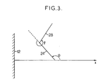
- the motors 22 and 26 can be controlled by a control circuit having a conventional general constitution, this circuit can include a calculating member supplying, from input data which can be constituted by the angles ⁇ and ⁇ (FIG. 3 ), or coordinates in x and y, the orientation, from a determined origin, to be given to motors 22 and 26.
- this circuit can include a calculating member supplying, from input data which can be constituted by the angles ⁇ and ⁇ (FIG. 3 ), or coordinates in x and y, the orientation, from a determined origin, to be given to motors 22 and 26.
- this singular point is located in the middle position, that is to say when the means 30 are located on the axis of the first motor, the levers 24 and 28 being then folded over one another.
Landscapes
- Physics & Mathematics (AREA)
- Engineering & Computer Science (AREA)
- Astronomy & Astrophysics (AREA)
- General Physics & Mathematics (AREA)
- Remote Sensing (AREA)
- Aviation & Aerospace Engineering (AREA)
- Aerials With Secondary Devices (AREA)
- Variable-Direction Aerials And Aerial Arrays (AREA)
Applications Claiming Priority (2)
| Application Number | Priority Date | Filing Date | Title |
|---|---|---|---|
| FR9005479 | 1990-04-30 | ||
| FR9005479A FR2661560B1 (fr) | 1990-04-30 | 1990-04-30 | Dispositif de pointage d'un reflecteur d'antenne. |
Publications (2)
| Publication Number | Publication Date |
|---|---|
| EP0455543A1 true EP0455543A1 (de) | 1991-11-06 |
| EP0455543B1 EP0455543B1 (de) | 1994-08-10 |
Family
ID=9396222
Family Applications (1)
| Application Number | Title | Priority Date | Filing Date |
|---|---|---|---|
| EP19910401103 Expired - Lifetime EP0455543B1 (de) | 1990-04-30 | 1991-04-25 | Vorrichtung zur Ausrichtung einer Reflektorantenne |
Country Status (3)
| Country | Link |
|---|---|
| EP (1) | EP0455543B1 (de) |
| DE (1) | DE69103322D1 (de) |
| FR (1) | FR2661560B1 (de) |
Cited By (1)
| Publication number | Priority date | Publication date | Assignee | Title |
|---|---|---|---|---|
| ES2039164A2 (es) * | 1992-01-30 | 1993-08-16 | Sener Ing & Sist | Mecanismo de ajuste de alta precision para el posicionado correcto de estructuras deformables. |
Citations (5)
| Publication number | Priority date | Publication date | Assignee | Title |
|---|---|---|---|---|
| FR2502404A1 (fr) * | 1981-03-20 | 1982-09-24 | Matra | Dispositif de montage articule, notamment d'un sous-ensemble de satellite artificiel |
| GB2127624A (en) * | 1982-09-22 | 1984-04-11 | Rca Corp | Antenna mounting system |
| DE3411838A1 (de) * | 1984-03-30 | 1985-10-10 | ANT Nachrichtentechnik GmbH, 7150 Backnang | Schwenkstrahlantenne fuer weltraumfunkstellen |
| FR2578687A1 (fr) * | 1985-03-05 | 1986-09-12 | Hardricourt Constr Blindees | Dispositif de support et de reglage d'un radar notamment sur un vehicule ou sur un shelter, et notamment un vehicule blinde |
| DE3835316A1 (de) * | 1988-10-17 | 1990-04-19 | Neuberger Nachrichten Und Ante | Parabolantennenhalterung |
-
1990
- 1990-04-30 FR FR9005479A patent/FR2661560B1/fr not_active Expired - Fee Related
-
1991
- 1991-04-25 EP EP19910401103 patent/EP0455543B1/de not_active Expired - Lifetime
- 1991-04-25 DE DE69103322T patent/DE69103322D1/de not_active Expired - Lifetime
Patent Citations (5)
| Publication number | Priority date | Publication date | Assignee | Title |
|---|---|---|---|---|
| FR2502404A1 (fr) * | 1981-03-20 | 1982-09-24 | Matra | Dispositif de montage articule, notamment d'un sous-ensemble de satellite artificiel |
| GB2127624A (en) * | 1982-09-22 | 1984-04-11 | Rca Corp | Antenna mounting system |
| DE3411838A1 (de) * | 1984-03-30 | 1985-10-10 | ANT Nachrichtentechnik GmbH, 7150 Backnang | Schwenkstrahlantenne fuer weltraumfunkstellen |
| FR2578687A1 (fr) * | 1985-03-05 | 1986-09-12 | Hardricourt Constr Blindees | Dispositif de support et de reglage d'un radar notamment sur un vehicule ou sur un shelter, et notamment un vehicule blinde |
| DE3835316A1 (de) * | 1988-10-17 | 1990-04-19 | Neuberger Nachrichten Und Ante | Parabolantennenhalterung |
Cited By (1)
| Publication number | Priority date | Publication date | Assignee | Title |
|---|---|---|---|---|
| ES2039164A2 (es) * | 1992-01-30 | 1993-08-16 | Sener Ing & Sist | Mecanismo de ajuste de alta precision para el posicionado correcto de estructuras deformables. |
Also Published As
| Publication number | Publication date |
|---|---|
| DE69103322D1 (de) | 1994-09-15 |
| EP0455543B1 (de) | 1994-08-10 |
| FR2661560B1 (fr) | 1992-08-07 |
| FR2661560A1 (fr) | 1991-10-31 |
Similar Documents
| Publication | Publication Date | Title |
|---|---|---|
| EP2630379B1 (de) | Kompaktes flexibles kardangelenk und raumfahrzeug mit einem derartigen gelenk | |
| EP0055720B1 (de) | Vorrichtung zur orientierung und einstellung einer nutzlast | |
| WO1999038044A1 (fr) | Ensemble de montage et de correction de position d'un organe, tel qu'un miroir, d'un telescope spatial | |
| EP2256039A1 (de) | Durchgehender Zapfen mit flexiblen Elementen, und mit einem solchen Zapfen ausgestattetes Raumschiff | |
| EP1964778B1 (de) | Drehgelenk mit Blattfedern | |
| EP3947158B1 (de) | Vorrichtung zum auslösen und zeigen eines von einem raumfahrzeug getragenen geräteteils | |
| EP1485292B1 (de) | Steuermomentkreisel für die lageregelung eines raumfahrzeuges | |
| EP2706267B1 (de) | Vorrichtung zur Winkelpositionierung, die zwei mechanische Bewegungsübertragungseinheiten umfasst, die beide jeweils an zwei Totpunkten verschachtelt sind | |
| EP0455543B1 (de) | Vorrichtung zur Ausrichtung einer Reflektorantenne | |
| WO2003066288A1 (fr) | Dispositif de deplacement spherique d'un element | |
| FR2646023A1 (fr) | Dispositif de pointage d'antenne, satellite equipe d'un tel dispositif et procede de pointage d'antenne utilisant un tel dispositif | |
| EP3675278A1 (de) | Mehrfachstrahlantenne mit regulierbarer ausrichtung | |
| EP0056550A2 (de) | Vorrichtung zum Ausrichten nach zwei senkrechten Achsen, insbesondere für eine Mikrowellenantenne | |
| EP0032081A1 (de) | Antenne mit einstellbarer Strahlrichtung für einen Nachrichtensatelliten | |
| EP1635485B1 (de) | Optisches Übertragungsverfahren zwischen einem Terminal an Bord eines Raumfahrzeuges, und Raumfahrzeug für das Verfahren | |
| CA2060773C (fr) | Dispositif de support et d'entrainement en rotation d'une charge utile par rapport a une structure, notamment pour un mecanisme de pointage d'antenne de satellite | |
| WO2016066395A1 (fr) | Dispositif d'orientation d'un élément mobile du type plateau d'antenne | |
| EP2703691B1 (de) | Vorrichtung zur Winkeleinstellung mit drei Totpunkten | |
| CA3165023C (fr) | Radiateur a ensoleillement reduit et systeme de guidage pour satellite geostationnaire | |
| FR2739461A1 (fr) | Dispositif a imagerie video, utilisable pour autodirecteur infrarouge passif | |
| EP3870408B1 (de) | Verfahren zur bewirkung, dass ein werkzeug am ende eines gelenkarms ohne gleiten gegen eine oberfläche drückt, und vorrichtung zur durchführung davon | |
| FR2663789A1 (fr) | Dispositif de deplacement d'un organe et application au pointage d'un reflecteur d'antenne. | |
| FR3047114A1 (fr) | Ensemble reflecteur d'antenne a source fixe adaptee pour etre montee sur un satellite | |
| FR3033024A1 (fr) | Mecanisme de positionnement |
Legal Events
| Date | Code | Title | Description |
|---|---|---|---|
| PUAI | Public reference made under article 153(3) epc to a published international application that has entered the european phase |
Free format text: ORIGINAL CODE: 0009012 |
|
| AK | Designated contracting states |
Kind code of ref document: A1 Designated state(s): DE ES GB IT NL SE |
|
| 17P | Request for examination filed |
Effective date: 19911209 |
|
| 17Q | First examination report despatched |
Effective date: 19931208 |
|
| GRAA | (expected) grant |
Free format text: ORIGINAL CODE: 0009210 |
|
| AK | Designated contracting states |
Kind code of ref document: B1 Designated state(s): DE ES GB IT NL SE |
|
| PG25 | Lapsed in a contracting state [announced via postgrant information from national office to epo] |
Ref country code: NL Effective date: 19940810 Ref country code: ES Free format text: THE PATENT HAS BEEN ANNULLED BY A DECISION OF A NATIONAL AUTHORITY Effective date: 19940810 |
|
| GBT | Gb: translation of ep patent filed (gb section 77(6)(a)/1977) |
Effective date: 19940810 |
|
| REF | Corresponds to: |
Ref document number: 69103322 Country of ref document: DE Date of ref document: 19940915 |
|
| ITF | It: translation for a ep patent filed | ||
| PG25 | Lapsed in a contracting state [announced via postgrant information from national office to epo] |
Ref country code: SE Effective date: 19941110 |
|
| PG25 | Lapsed in a contracting state [announced via postgrant information from national office to epo] |
Ref country code: DE Effective date: 19941111 |
|
| NLV1 | Nl: lapsed or annulled due to failure to fulfill the requirements of art. 29p and 29m of the patents act | ||
| PLBE | No opposition filed within time limit |
Free format text: ORIGINAL CODE: 0009261 |
|
| STAA | Information on the status of an ep patent application or granted ep patent |
Free format text: STATUS: NO OPPOSITION FILED WITHIN TIME LIMIT |
|
| 26N | No opposition filed | ||
| PGFP | Annual fee paid to national office [announced via postgrant information from national office to epo] |
Ref country code: GB Payment date: 19960419 Year of fee payment: 6 |
|
| PG25 | Lapsed in a contracting state [announced via postgrant information from national office to epo] |
Ref country code: GB Effective date: 19970425 |
|
| GBPC | Gb: european patent ceased through non-payment of renewal fee |
Effective date: 19970425 |
|
| PG25 | Lapsed in a contracting state [announced via postgrant information from national office to epo] |
Ref country code: IT Free format text: LAPSE BECAUSE OF NON-PAYMENT OF DUE FEES;WARNING: LAPSES OF ITALIAN PATENTS WITH EFFECTIVE DATE BEFORE 2007 MAY HAVE OCCURRED AT ANY TIME BEFORE 2007. THE CORRECT EFFECTIVE DATE MAY BE DIFFERENT FROM THE ONE RECORDED. Effective date: 20050425 |