EP0455555B1 - System zum Aerosolspritzen für die Erzeugung von Verbundschichten durch Pyrolyse - Google Patents
System zum Aerosolspritzen für die Erzeugung von Verbundschichten durch Pyrolyse Download PDFInfo
- Publication number
- EP0455555B1 EP0455555B1 EP91401149A EP91401149A EP0455555B1 EP 0455555 B1 EP0455555 B1 EP 0455555B1 EP 91401149 A EP91401149 A EP 91401149A EP 91401149 A EP91401149 A EP 91401149A EP 0455555 B1 EP0455555 B1 EP 0455555B1
- Authority
- EP
- European Patent Office
- Prior art keywords
- aerosol
- injection
- chamber
- additional air
- case
- Prior art date
- Legal status (The legal status is an assumption and is not a legal conclusion. Google has not performed a legal analysis and makes no representation as to the accuracy of the status listed.)
- Expired - Lifetime
Links
- 239000000443 aerosol Substances 0.000 title claims description 66
- 238000002347 injection Methods 0.000 title claims description 65
- 239000007924 injection Substances 0.000 title claims description 65
- 238000000197 pyrolysis Methods 0.000 title claims description 20
- 239000002131 composite material Substances 0.000 title claims description 6
- 239000000758 substrate Substances 0.000 claims description 34
- 238000009834 vaporization Methods 0.000 claims description 17
- 230000008016 vaporization Effects 0.000 claims description 17
- 238000010438 heat treatment Methods 0.000 claims description 10
- 239000007792 gaseous phase Substances 0.000 claims description 8
- 239000012071 phase Substances 0.000 claims description 7
- 238000004519 manufacturing process Methods 0.000 claims description 6
- 230000002093 peripheral effect Effects 0.000 claims description 3
- 239000012808 vapor phase Substances 0.000 description 14
- 239000007789 gas Substances 0.000 description 12
- 239000000047 product Substances 0.000 description 7
- 239000007787 solid Substances 0.000 description 7
- 239000012159 carrier gas Substances 0.000 description 6
- 239000007788 liquid Substances 0.000 description 6
- 239000002243 precursor Substances 0.000 description 6
- 239000002245 particle Substances 0.000 description 5
- 238000000576 coating method Methods 0.000 description 4
- 238000009434 installation Methods 0.000 description 4
- 239000010410 layer Substances 0.000 description 4
- 230000005855 radiation Effects 0.000 description 4
- 239000011248 coating agent Substances 0.000 description 3
- 230000008021 deposition Effects 0.000 description 3
- 238000009826 distribution Methods 0.000 description 3
- 238000000034 method Methods 0.000 description 3
- 239000002904 solvent Substances 0.000 description 3
- 230000015572 biosynthetic process Effects 0.000 description 2
- 230000003749 cleanliness Effects 0.000 description 2
- 238000001816 cooling Methods 0.000 description 2
- 230000002349 favourable effect Effects 0.000 description 2
- 238000009776 industrial production Methods 0.000 description 2
- 240000008042 Zea mays Species 0.000 description 1
- 230000002457 bidirectional effect Effects 0.000 description 1
- 238000006243 chemical reaction Methods 0.000 description 1
- 239000011247 coating layer Substances 0.000 description 1
- 150000001875 compounds Chemical class 0.000 description 1
- 239000012141 concentrate Substances 0.000 description 1
- 238000009833 condensation Methods 0.000 description 1
- 230000005494 condensation Effects 0.000 description 1
- 239000007859 condensation product Substances 0.000 description 1
- 238000005137 deposition process Methods 0.000 description 1
- 238000010586 diagram Methods 0.000 description 1
- 230000000694 effects Effects 0.000 description 1
- 230000008030 elimination Effects 0.000 description 1
- 238000003379 elimination reaction Methods 0.000 description 1
- 238000000605 extraction Methods 0.000 description 1
- 239000012467 final product Substances 0.000 description 1
- 239000012535 impurity Substances 0.000 description 1
- 235000011837 pasties Nutrition 0.000 description 1
- 238000002360 preparation method Methods 0.000 description 1
- 230000001105 regulatory effect Effects 0.000 description 1
- 239000007790 solid phase Substances 0.000 description 1
- 239000000243 solution Substances 0.000 description 1
- 239000007921 spray Substances 0.000 description 1
- 238000005979 thermal decomposition reaction Methods 0.000 description 1
Images



Classifications
-
- C—CHEMISTRY; METALLURGY
- C23—COATING METALLIC MATERIAL; COATING MATERIAL WITH METALLIC MATERIAL; CHEMICAL SURFACE TREATMENT; DIFFUSION TREATMENT OF METALLIC MATERIAL; COATING BY VACUUM EVAPORATION, BY SPUTTERING, BY ION IMPLANTATION OR BY CHEMICAL VAPOUR DEPOSITION, IN GENERAL; INHIBITING CORROSION OF METALLIC MATERIAL OR INCRUSTATION IN GENERAL
- C23C—COATING METALLIC MATERIAL; COATING MATERIAL WITH METALLIC MATERIAL; SURFACE TREATMENT OF METALLIC MATERIAL BY DIFFUSION INTO THE SURFACE, BY CHEMICAL CONVERSION OR SUBSTITUTION; COATING BY VACUUM EVAPORATION, BY SPUTTERING, BY ION IMPLANTATION OR BY CHEMICAL VAPOUR DEPOSITION, IN GENERAL
- C23C18/00—Chemical coating by decomposition of either liquid compounds or solutions of the coating forming compounds, without leaving reaction products of surface material in the coating; Contact plating
- C23C18/02—Chemical coating by decomposition of either liquid compounds or solutions of the coating forming compounds, without leaving reaction products of surface material in the coating; Contact plating by thermal decomposition
-
- B—PERFORMING OPERATIONS; TRANSPORTING
- B05—SPRAYING OR ATOMISING IN GENERAL; APPLYING FLUENT MATERIALS TO SURFACES, IN GENERAL
- B05B—SPRAYING APPARATUS; ATOMISING APPARATUS; NOZZLES
- B05B14/00—Arrangements for collecting, re-using or eliminating excess spraying material
-
- B—PERFORMING OPERATIONS; TRANSPORTING
- B05—SPRAYING OR ATOMISING IN GENERAL; APPLYING FLUENT MATERIALS TO SURFACES, IN GENERAL
- B05B—SPRAYING APPARATUS; ATOMISING APPARATUS; NOZZLES
- B05B17/00—Apparatus for spraying or atomising liquids or other fluent materials, not covered by the preceding groups
- B05B17/04—Apparatus for spraying or atomising liquids or other fluent materials, not covered by the preceding groups operating with special methods
Definitions
- the present invention relates generally to installations and apparatuses which make it possible to produce composite layers which are deposited on substrates.
- said substrates are heated and pass through the muffle of an oven where they are placed in the presence of an aerosol of droplets containing a solute which constitutes the precursor of the final product with which they are coated.
- the invention relates more precisely still, the system which makes it possible to inject this aerosol inside the furnace in which the substrates to be coated pass.
- the aerosol of liquid droplets containing, as solute, the precursor of the product to be deposited is formed and transported in a gaseous phase injected at the same time as the aerosol in the oven, and it is when it arrives in the immediate vicinity (a few millimeters for example) of the heated substrates that the two phenomena occur which allow them to be coated. Firstly, the droplets and the solute vaporize under the influence of heat and, secondly, the heat radiated by these same substrates cause thermal decomposition or pyrolysis of the precursor solute, the useful part of which the coating is then deposited directly on the substrate itself.
- This technique therefore makes it possible to deposit products by pyrolysis of a chemical compound in solution in a solvent, even if the precursor solute of the deposition product has a vapor pressure too low to be vaporizable directly at room temperature.
- FIG. 1 which is a perspective view of a pyrolysis oven, the muffle 2, of elongated parallelepiped shape, in which a conveyor belt 4 supporting the substrates 6 to be coated runs.
- the diagram in FIG. 1 shows the furnace at the level of one of its aerosol injection devices 8 essentially consisting of a box, also of parallelepiped shape, which fits onto the muffle 2.
- the injection box 8 contains essentially an injection nozzle 10 proper, which will moreover be described in more detail with reference to FIG. 2, and, at its top, an inlet 12 for additional air.
- a plate 14 perforated with holes makes it possible to homogenize and distribute the additional air entering through the pipe 12 throughout the volume of the injection box 8.
- the injector 10 receives at its ends 16 and 18 ' aerosol to be injected into the box 8, which aerosol escapes into the injection box 8 through orifices 20 of the injector 10 located at the top of the latter.
- This aerosol contains in its liquid droplets, a solute which is used as a body precursor to be deposited on the heated substrates 6 and which will appear, after vaporization of this aerosol under the effect of pyrolysis which occurs on contact with hot substrates 6 and aerosol vapor.
- deflector plates such as 22 serving to homogenize and regulate the flow of the vapor phase in a manner known to those skilled in the art and which not important to describe here for the understanding of the invention.
- a suction nozzle 24 of generally frustoconical shape which allows to adjust the flow rate and suction of the residual vapor phase.
- the injection nozzle 10 of FIG. 1 is shown, with its two inlets 16 and 18 for the aerosol entrained by its carrier gas as well as an annular casing 26 intended to receive a thermostatic liquid which enters at one end 28 in this chamber 26 to exit therefrom at the other end 30.
- the orifices 20 which are located at the top and through which escapes according to the paths visualized by arrows l ' aerosol entrained by its carrier gas.
- the operating temperature of the nozzle 10 is most often regulated by the liquid which circulates in the peripheral annular zone 26 at a temperature of the order of 50 to 60 ° C.
- the vaporization, the pyrolysis and the deposition take place in a very narrow zone subjected to complex heat exchanges, which requires a delicate adjustment of different parameters especially if one wants to vary the speed of movement of the substrates in the furnace or gas injection rates for specific manufacturing requirements.
- the present invention specifically relates to a new aerosol injection system for developing composite layers by pyrolysis which solves the above problems by adding to the latter autonomous heating means and eliminating the injection nozzle as such. .
- This new aerosol injection system thus makes it possible to improve and very precisely control the evolution of the aerosol and of the gaseous phase which drives it from the top of the injection box to its base. by the various means associated with it.
- the injection chamber located at the top plays the role of condensation chamber in which the aerosols entrained by their carrier gas eventually get rid of the condensates which can occur, thanks to the plate pierced with holes whose various orifices are equipped with chimneys which allow only the aerosol to pass through while any condensate is collected on the plate and evacuated outside.
- the aerosol passage surface both at the outlet of the supply openings and at the level of the various vertical chimneys of the plate pierced with holes leads to a distribution surface of the order of ten times greater than what was that of the conventional nozzle of the prior art which reduces the speed of passage of the gases by ensuring them a good homogeneity of distribution, even at high flow rates.
- the vaporization chamber which has in its walls autonomous heating resistors in several adjustable groups allows an easy and very precise control of the thermal gradient within this chamber in the vertical direction and consequently a total control of the conditions of passage of the state aerosol in the vapor state.
- This provision is essential, because this avoids the undesirable formation of various solid particles and has, in addition, the great advantage of not cooling the substrates which run on the heating strip in line with the injection system, since the heat of vaporization of the aerosol is no longer taken from the thermal radiation of the substrates themselves.
- the vapor phase outlet injector allows, for example using a thermocouple, to accurately determine the temperature of the vapor phase and gas outlet, that is to say to prepare the conditions optimal pyrolysis which will take place in an area very close to heated substrates.
- the aerosol and the additional air are introduced into the supply opening (s) of the chamber. injection via two concentric conduits, the central conduit of which carries the aerosol and the peripheral annular conduit of additional air.
- the diameter of the feed openings being incommensurate with that of the holes of the injection nozzle according to the prior art, allows much more favorable injection conditions.
- the injection chamber is provided with two supply openings situated with a transverse offset on two side walls facing each other.
- This arrangement allows a better distribution of the gaseous threads in the injection chamber by avoiding the harmful turbulence which would not fail to occur if the supply openings, being two in number, were located face to face on two opposite side walls .
- the number of groups of independent heating resistors provided in the walls of the vaporization chamber can be obviously any, but most often experience has shown that three groups of independently adjustable resistors allow sufficiently precise control of the temperature gradient of injection of the vapor phase.
- the outlet injector of the aerosol injection system may comprise one or two unidirectional outlet slots; when there are two of them, the unidirectional outlet slots are symmetrical with respect to the box and directed for one in the direction of travel of the strip and for the other in the opposite direction.
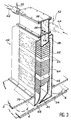
- FIG 3 there is shown an aerosol injection system 32 according to the invention.
- This aerosol injection system is fixed like those of the prior art to the upper part of the muffle 2 of a heating oven in which a conveyor belt 34 containing samples 6 passes in the form of substrate to be coated.
- the injection system 32 essentially comprises from top to bottom, three parts, namely: at the top, an injection chamber 36 followed on the common path of the aerosol and the gaseous phase by a vaporization chamber 38 and an outlet injector 40.
- the aerosol injection system 32 serves, like the injection system of the prior art, to convey the aerosol, its carrier gas and the air additional, up to the immediate vicinity of the substrates 6 to be coated by pyrolysis of a precursor solute of the product to be deposited on the substrate 6.
- This injection chamber comprises in its upper part, two aerosol supply openings 39 and 39a connected to tubes for supplying the aerosol transported by its carrier gas, respectively 42 and 44.
- the axes of the pipes 42 and 44 are offset transversely and the two gas jets penetrate into the injection chamber 36 without meeting directly.
- the injection of the additional air necessary for the transfer of the gaseous phase and / or for the reaction takes place along annular zones 46 and 48 of the inlet conduits 42 and 44, these zones 46 and 48 being each supplied by an additional air inlet pipe, respectively 50 and 52.
- the injection chamber 36 is terminated at its lower part by a plate 54 pierced with a number of holes each of which is equipped with a short tubular element such as 56 which opens out in the manner of a vertical chimney in the upper part of the injection chamber 36.
- These chimneys 56 constitute free passages of the aerosol and of the gaseous phase towards the vaporization chamber 38 immediately below; on the other hand, the plate 54 serves to collect all the undesirable condensation products which may form from the gas phase and which flow on the walls of the chamber 36, then on the surface of the plate 54, are finally evacuated towards the outside by a rejection tube 58 thus avoiding their passage in the vaporization chamber 38.
- this vaporization chamber 38 which follows on the path of aerosols and the vapor phase to the previous injection chamber 36.
- this vaporization chamber 38 is provided with a double wall 60 containing over the entire height a certain number of groups - here three in number - of heating resistors 62, 64 and 66, each of these groups being powered and adjustable independently.
- This is precisely one of the essential means of the invention, by which one adjusts and optimizes, as a function of the flow rates or of the solvent used, the outlet temperature of the vapor phase at the level of the subsequent outlet injector 40.
- the lower part of the injection system object of the invention consisting of the outlet injector 40 of the aerosol in the vapor phase, is produced by means of a slot 68 extending along a line segment 70 of general direction perpendicular to the direction of travel of the substrates 6 on the strip 34; the opening of this slot 68 is oriented so as to ensure the routing of the vapor phase as parallel as possible to the strip 34 and to the surface of the moving substrates 6. It is in the immediate vicinity of the surface of these hot substrates that the pyrolysis and deposition operation takes place. As the vapor phase produced in the vaporization chamber 38 is free of any liquid or solid impurity, these deposits are thus produced under excellent conditions of cleanliness and homogeneity.
- This bidirectional injector system makes it possible to practically quadruple the quantities deposited on the substrate and in any case the presence of an extraction - not shown - on either side of this injection system, allows a much more favorable arrangement for gas flows inside the injection system.
Landscapes
- Chemical & Material Sciences (AREA)
- Materials Engineering (AREA)
- Thermal Sciences (AREA)
- General Chemical & Material Sciences (AREA)
- Chemical Kinetics & Catalysis (AREA)
- Engineering & Computer Science (AREA)
- Physics & Mathematics (AREA)
- Mechanical Engineering (AREA)
- Metallurgy (AREA)
- Organic Chemistry (AREA)
- Nozzles (AREA)
- Medicinal Preparation (AREA)
- Coating Apparatus (AREA)
- Surface Treatment Of Glass (AREA)
Claims (6)
- System zum Aerosolspritzen von Tröpfchen, die fortbewegt werden in einer Gasphase und die einen gelösten Stoff enthalten zur Erzeugung von Verbundschichten durch Pyrolyse des gelösten Stoffs auf erwärmten Substraten (6) beim Durchlaufen der Muffel (2) eines Ofens, der einen vertikalen Kasten (8) von im wesentlichen parallelflacher Form umfaßt, durch seine Basis an die genannte Muffel adaptierbar, an seiner Oberseite mit Aerosol und zusätzlicher Luft versorgt, wobei der genannte Kasten dazu dient, das Aerosol zu kanalisieren, von seinem Eintritt an der Oberseite bis zu seiner Basis, wo es auf die verschiedenen erwärmten Substrate trifft,
dadurch gekennzeichnet,
daß dieser Kasten drei Teile umfaßt, nämlich von oben nach unten und auf der gemeinsamen Bahn des Aerosols und der Gasphase:- eine Einspritzkammer (36), in ihrem oberen Teil mit wenigstens einer Öffnung zur Versorgung mit Aerosol und mit zusätzlicher Luft versehen und, in ihrem unteren Teil, mit einer Platte (54), von Löchern durchbohrt, von denen jedes ausgestattet ist mit einem kurzen röhrenförmigen Element (56) nach Art eines vertikalen Kamins, der in die Einspritzkammer mündet, wobei die verschiedenen Kamine (56) den freien Durchgang des Aerosols und der zusätzlichen Luft in Richtung der Basis des Kastens gewährleisten;- eine Verdampfungskammer (38) der Aerosoltröpfchen, versehen mit einer Seiten-Doppelwand, die Heizwiderstände (62,64,66) enthält, die über die gesamte Höhe verteilt sind auf mehrere Gruppen, wovon jede auf selbstständige Weise regelbar ist;- eine Austrittsdüse des Aerosols in der Dampfphase (40), in Kontinuität mit der unteren Wand des Kastens und mit wenigstens einem Schlitz (68) versehen, gemäß einer Strecke (70) in einer Richtung, die im wesentlichen senkrecht ist zu der Fortbewegungsrichtung der zu beschichtetenden Substrate (6), jedoch mit einer Öffnung, die so ausgerichtet ist, daß sie diese Dampfphase so parallel wie möglich zu ihrer Fläche auf die Substrate leitet. - System zum Aerosolspritzen nach Anspruch 1, dadurch gekennzeichnet, daß das Aerosol und die zusätzliche Luft in die Versorgungsöffnung(en) der Einspritzkammer (36) eingeleitet werden über zwei konzentrische Leitungen, wobei die zentrale Leitung (42,44) das Aerosol fördert, und die ringförmige periphere Leitung (46,48) die zusätzliche Luft fördert.
- System zum Aerosolspritzen nach einem der Ansprüche 1 und 2, dadurch gekennzeichnet, daß die Einspritzkammer (36) versehen ist mit zwei Versorgungsöffnungen (39,39a), versetzt angeordnet an zwei sich gegenüberstehenden Seitenwänden.
- System zum Aerosolspritzen nach Anspruch 1, dadurch gekennzeichnet, daß die Verdampfungskammer (38) drei Gruppen unabhängig regelbarer Widerstände umfaßt.
- System zum Aerosolspritzen nach Anspruch 1, dadurch gekennzeichnet, daß die Austrittsdüse (40) einen in einer Richtung verlaufenden Austrittsschlitz (68) aufweist.
- System zum Aerosolspritzen nach Anspruch 1, dadurch gekennzeichnet, daß die Austrittsdüse (40) zwei in einer Richtung verlaufenden Austrittsschlitze (72,74) aufweist, symetrisch bezüglich des Kastens, wobei der eine in die Richtung der Fortbewegung des Bandes weist und der andere in die entgegengesetzte Richtung.
Applications Claiming Priority (2)
| Application Number | Priority Date | Filing Date | Title |
|---|---|---|---|
| FR9005525 | 1990-05-02 | ||
| FR909005525A FR2661623B1 (fr) | 1989-04-04 | 1990-05-02 | Systeme d'injection d'aerosol pour elaboration de couches composites par pyrolyse. |
Publications (2)
| Publication Number | Publication Date |
|---|---|
| EP0455555A1 EP0455555A1 (de) | 1991-11-06 |
| EP0455555B1 true EP0455555B1 (de) | 1994-06-29 |
Family
ID=9396251
Family Applications (1)
| Application Number | Title | Priority Date | Filing Date |
|---|---|---|---|
| EP91401149A Expired - Lifetime EP0455555B1 (de) | 1990-05-02 | 1991-04-30 | System zum Aerosolspritzen für die Erzeugung von Verbundschichten durch Pyrolyse |
Country Status (5)
| Country | Link |
|---|---|
| US (1) | US5190592A (de) |
| EP (1) | EP0455555B1 (de) |
| JP (1) | JPH04228458A (de) |
| CA (1) | CA2041631A1 (de) |
| DE (1) | DE69102679T2 (de) |
Families Citing this family (5)
| Publication number | Priority date | Publication date | Assignee | Title |
|---|---|---|---|---|
| JP3222518B2 (ja) * | 1991-12-26 | 2001-10-29 | キヤノン株式会社 | 液体原料気化装置および薄膜形成装置 |
| JP2875458B2 (ja) * | 1993-07-16 | 1999-03-31 | 大日本スクリーン製造株式会社 | 基板の熱処理装置 |
| US6012647A (en) * | 1997-12-01 | 2000-01-11 | 3M Innovative Properties Company | Apparatus and method of atomizing and vaporizing |
| US6045864A (en) | 1997-12-01 | 2000-04-04 | 3M Innovative Properties Company | Vapor coating method |
| US7163587B2 (en) * | 2002-02-08 | 2007-01-16 | Axcelis Technologies, Inc. | Reactor assembly and processing method |
Family Cites Families (2)
| Publication number | Priority date | Publication date | Assignee | Title |
|---|---|---|---|---|
| FR2543165B1 (fr) * | 1983-03-21 | 1987-08-14 | Commissariat Energie Atomique | Procede et dispositif d'elaboration de couches composites, par superposition, en continu et en atmosphere controlee |
| GB2216903A (en) * | 1988-04-06 | 1989-10-18 | Ici Plc | Transparent conductive zinc oxide layer |
-
1991
- 1991-04-12 US US07/684,371 patent/US5190592A/en not_active Expired - Fee Related
- 1991-04-30 EP EP91401149A patent/EP0455555B1/de not_active Expired - Lifetime
- 1991-04-30 DE DE69102679T patent/DE69102679T2/de not_active Expired - Fee Related
- 1991-05-01 JP JP3100177A patent/JPH04228458A/ja active Pending
- 1991-05-01 CA CA002041631A patent/CA2041631A1/en not_active Abandoned
Also Published As
| Publication number | Publication date |
|---|---|
| US5190592A (en) | 1993-03-02 |
| CA2041631A1 (en) | 1991-11-03 |
| EP0455555A1 (de) | 1991-11-06 |
| DE69102679T2 (de) | 1995-01-12 |
| DE69102679D1 (de) | 1994-08-04 |
| JPH04228458A (ja) | 1992-08-18 |
Similar Documents
| Publication | Publication Date | Title |
|---|---|---|
| KR100780142B1 (ko) | 기재의 코팅방법 및 기재에 층을 코팅하기 위한 장치 | |
| EP0124432B1 (de) | Verfahren und Einrichtung zur Beschichtung eines Werkstücks mittels Plasmastrahl | |
| US6409839B1 (en) | Method and apparatus for vapor generation and film deposition | |
| US5835678A (en) | Liquid vaporizer system and method | |
| BE1008560A3 (fr) | Dispositif et procede pour former un revetement par pyrolyse. | |
| EP0455555B1 (de) | System zum Aerosolspritzen für die Erzeugung von Verbundschichten durch Pyrolyse | |
| EP0060221A1 (de) | Verfahren zum Überziehen eines Substrates mit einem anorganischen Oxid und Vorrichtung zur Anwendung dieses Verfahrens | |
| EP1098015A1 (de) | Verdampfer für CVD-Anlage | |
| FR2542636A1 (fr) | Procede et dispositif de distribution reguliere d'un solide pulverulent sur un substrat en vue de son revetement et substrat ainsi revetu | |
| JP2012510568A (ja) | トップダウン式の材料堆積用システム及び方法 | |
| EP0130919B1 (de) | Vorrichtung zum Verteilen von in einem Gas suspendierten pulverförmigen Stoffen | |
| FR2672518A1 (fr) | Buse a alimentation dissymetrique pour la formation d'une couche de revetement sur un ruban de verre, par pyrolyse d'un melange gazeux. | |
| EP0006064B1 (de) | Vorrichtung zum gleichmässigen Verteilen eines pulverförmigen Stoffes durch eine longitudinale Spalte und Anwendungen dieser Vorrichtung | |
| KR20160003578A (ko) | 박막 증착에서 여과 및 가스/증기 혼합 장치 | |
| FR2711274A1 (fr) | Appareil pour le dépôt chimique en phase vapeur. | |
| LU86664A1 (fr) | Dispositif et procede de formation d'un revetement sur du verre | |
| CH411826A (fr) | Procédé pour la fabrication d'adiponitrile et appareil pour la mise en oeuvre | |
| FR2661623A1 (fr) | Systeme d'injection d'aerosol pour elaboration de couches composites par pyrolyse. | |
| FR2542637A1 (fr) | Distribution reguliere d'un solide pulverulent sur un support en vue de son revetement | |
| EP0066661A1 (de) | Vorrichtung zum Trocknen von Bahnen durch Heissluft bei gleichzeitiger Unterstützung der Bahn, vorzugsweise von Papierbahnen aus Druckmaschinen | |
| EP0708062B1 (de) | Pyrolytische Beschichtungstechnik von gasförmigen Ausgangsgemischen | |
| EP0374023B1 (de) | Vorrichtung zum Auftragen eines in einem Gas verteilten pulverförmigen Feststoffes auf ein sich bewegendes Substrat | |
| EP0080607B1 (de) | Düse zum Agglomerieren | |
| EP0612566A1 (de) | Vorrichtung zur Verteilung von pulverförmigen Feststoffen auf ein Substrat zum Zweck seiner Beschichtung | |
| CH615407A5 (en) | Process and plant for the manufacture of fibres from a thermoplastic material |
Legal Events
| Date | Code | Title | Description |
|---|---|---|---|
| PUAI | Public reference made under article 153(3) epc to a published international application that has entered the european phase |
Free format text: ORIGINAL CODE: 0009012 |
|
| AK | Designated contracting states |
Kind code of ref document: A1 Designated state(s): CH DE GB IT LI NL |
|
| 17P | Request for examination filed |
Effective date: 19920410 |
|
| 17Q | First examination report despatched |
Effective date: 19930604 |
|
| GRAA | (expected) grant |
Free format text: ORIGINAL CODE: 0009210 |
|
| AK | Designated contracting states |
Kind code of ref document: B1 Designated state(s): CH DE GB IT LI NL |
|
| REF | Corresponds to: |
Ref document number: 69102679 Country of ref document: DE Date of ref document: 19940804 |
|
| ITF | It: translation for a ep patent filed | ||
| GBT | Gb: translation of ep patent filed (gb section 77(6)(a)/1977) |
Effective date: 19940916 |
|
| PLBE | No opposition filed within time limit |
Free format text: ORIGINAL CODE: 0009261 |
|
| STAA | Information on the status of an ep patent application or granted ep patent |
Free format text: STATUS: NO OPPOSITION FILED WITHIN TIME LIMIT |
|
| 26N | No opposition filed | ||
| PGFP | Annual fee paid to national office [announced via postgrant information from national office to epo] |
Ref country code: CH Payment date: 19970416 Year of fee payment: 7 |
|
| PG25 | Lapsed in a contracting state [announced via postgrant information from national office to epo] |
Ref country code: LI Free format text: LAPSE BECAUSE OF NON-PAYMENT OF DUE FEES Effective date: 19980430 Ref country code: CH Free format text: LAPSE BECAUSE OF NON-PAYMENT OF DUE FEES Effective date: 19980430 |
|
| REG | Reference to a national code |
Ref country code: CH Ref legal event code: PL |
|
| PGFP | Annual fee paid to national office [announced via postgrant information from national office to epo] |
Ref country code: GB Payment date: 20000425 Year of fee payment: 10 |
|
| PGFP | Annual fee paid to national office [announced via postgrant information from national office to epo] |
Ref country code: NL Payment date: 20000428 Year of fee payment: 10 |
|
| PGFP | Annual fee paid to national office [announced via postgrant information from national office to epo] |
Ref country code: DE Payment date: 20000517 Year of fee payment: 10 |
|
| PG25 | Lapsed in a contracting state [announced via postgrant information from national office to epo] |
Ref country code: GB Free format text: LAPSE BECAUSE OF NON-PAYMENT OF DUE FEES Effective date: 20010430 |
|
| PG25 | Lapsed in a contracting state [announced via postgrant information from national office to epo] |
Ref country code: NL Free format text: LAPSE BECAUSE OF NON-PAYMENT OF DUE FEES Effective date: 20011101 |
|
| GBPC | Gb: european patent ceased through non-payment of renewal fee |
Effective date: 20010430 |
|
| NLV4 | Nl: lapsed or anulled due to non-payment of the annual fee |
Effective date: 20011101 |
|
| PG25 | Lapsed in a contracting state [announced via postgrant information from national office to epo] |
Ref country code: DE Free format text: LAPSE BECAUSE OF NON-PAYMENT OF DUE FEES Effective date: 20020201 |
|
| PG25 | Lapsed in a contracting state [announced via postgrant information from national office to epo] |
Ref country code: IT Free format text: LAPSE BECAUSE OF NON-PAYMENT OF DUE FEES;WARNING: LAPSES OF ITALIAN PATENTS WITH EFFECTIVE DATE BEFORE 2007 MAY HAVE OCCURRED AT ANY TIME BEFORE 2007. THE CORRECT EFFECTIVE DATE MAY BE DIFFERENT FROM THE ONE RECORDED. Effective date: 20050430 |