EP0060221A1 - Verfahren zum Überziehen eines Substrates mit einem anorganischen Oxid und Vorrichtung zur Anwendung dieses Verfahrens - Google Patents
Verfahren zum Überziehen eines Substrates mit einem anorganischen Oxid und Vorrichtung zur Anwendung dieses Verfahrens Download PDFInfo
- Publication number
- EP0060221A1 EP0060221A1 EP82810096A EP82810096A EP0060221A1 EP 0060221 A1 EP0060221 A1 EP 0060221A1 EP 82810096 A EP82810096 A EP 82810096A EP 82810096 A EP82810096 A EP 82810096A EP 0060221 A1 EP0060221 A1 EP 0060221A1
- Authority
- EP
- European Patent Office
- Prior art keywords
- nozzle
- nozzles
- gas
- substrate
- flows
- Prior art date
- Legal status (The legal status is an assumption and is not a legal conclusion. Google has not performed a legal analysis and makes no representation as to the accuracy of the status listed.)
- Granted
Links
- 239000000758 substrate Substances 0.000 title claims abstract description 21
- 238000000576 coating method Methods 0.000 title claims abstract description 17
- 239000011248 coating agent Substances 0.000 title claims abstract description 13
- 238000000034 method Methods 0.000 title claims description 15
- 229910052809 inorganic oxide Inorganic materials 0.000 title 1
- 239000007789 gas Substances 0.000 claims abstract description 61
- 239000003153 chemical reaction reagent Substances 0.000 claims abstract description 16
- 239000011521 glass Substances 0.000 claims abstract description 15
- 230000000694 effects Effects 0.000 claims abstract description 7
- 238000002156 mixing Methods 0.000 claims abstract description 7
- 238000006243 chemical reaction Methods 0.000 claims description 15
- XLYOFNOQVPJJNP-UHFFFAOYSA-N water Chemical compound O XLYOFNOQVPJJNP-UHFFFAOYSA-N 0.000 claims description 13
- 239000012159 carrier gas Substances 0.000 claims description 12
- 239000000203 mixture Substances 0.000 claims description 11
- 239000000376 reactant Substances 0.000 claims description 9
- 238000000151 deposition Methods 0.000 claims description 6
- 239000007795 chemical reaction product Substances 0.000 claims description 5
- 239000000463 material Substances 0.000 claims description 5
- 229910006404 SnO 2 Inorganic materials 0.000 claims description 4
- 238000000354 decomposition reaction Methods 0.000 claims description 3
- 238000001704 evaporation Methods 0.000 claims description 3
- 229910052500 inorganic mineral Inorganic materials 0.000 claims description 3
- 239000007788 liquid Substances 0.000 claims description 3
- 239000011707 mineral Substances 0.000 claims description 3
- 239000011148 porous material Substances 0.000 claims description 3
- 239000012265 solid product Substances 0.000 claims description 3
- 239000012808 vapor phase Substances 0.000 claims description 3
- 238000013019 agitation Methods 0.000 claims 1
- 239000011261 inert gas Substances 0.000 claims 1
- 239000000047 product Substances 0.000 claims 1
- 230000001105 regulatory effect Effects 0.000 claims 1
- XOLBLPGZBRYERU-UHFFFAOYSA-N tin dioxide Chemical compound O=[Sn]=O XOLBLPGZBRYERU-UHFFFAOYSA-N 0.000 abstract 2
- 238000005229 chemical vapour deposition Methods 0.000 description 5
- 239000010410 layer Substances 0.000 description 5
- 239000000919 ceramic Substances 0.000 description 3
- 229910052802 copper Inorganic materials 0.000 description 3
- 239000010949 copper Substances 0.000 description 3
- 230000008021 deposition Effects 0.000 description 3
- PXHVJJICTQNCMI-UHFFFAOYSA-N nickel Substances [Ni] PXHVJJICTQNCMI-UHFFFAOYSA-N 0.000 description 3
- RYGMFSIKBFXOCR-UHFFFAOYSA-N Copper Chemical compound [Cu] RYGMFSIKBFXOCR-UHFFFAOYSA-N 0.000 description 2
- 238000009826 distribution Methods 0.000 description 2
- 230000008020 evaporation Effects 0.000 description 2
- 239000005329 float glass Substances 0.000 description 2
- XEEYBQQBJWHFJM-UHFFFAOYSA-N iron Substances [Fe] XEEYBQQBJWHFJM-UHFFFAOYSA-N 0.000 description 2
- 239000002184 metal Substances 0.000 description 2
- 229910052751 metal Inorganic materials 0.000 description 2
- 229910052759 nickel Inorganic materials 0.000 description 2
- 230000008569 process Effects 0.000 description 2
- 229910000906 Bronze Inorganic materials 0.000 description 1
- 239000000654 additive Substances 0.000 description 1
- 238000013459 approach Methods 0.000 description 1
- 239000010974 bronze Substances 0.000 description 1
- 230000008859 change Effects 0.000 description 1
- 239000011247 coating layer Substances 0.000 description 1
- 238000009833 condensation Methods 0.000 description 1
- 230000005494 condensation Effects 0.000 description 1
- KUNSUQLRTQLHQQ-UHFFFAOYSA-N copper tin Chemical compound [Cu].[Sn] KUNSUQLRTQLHQQ-UHFFFAOYSA-N 0.000 description 1
- 239000006185 dispersion Substances 0.000 description 1
- 238000006073 displacement reaction Methods 0.000 description 1
- 239000012154 double-distilled water Substances 0.000 description 1
- 238000005485 electric heating Methods 0.000 description 1
- 239000011152 fibreglass Substances 0.000 description 1
- 230000004907 flux Effects 0.000 description 1
- 239000003365 glass fiber Substances 0.000 description 1
- 238000010438 heat treatment Methods 0.000 description 1
- 230000010354 integration Effects 0.000 description 1
- 229910052742 iron Inorganic materials 0.000 description 1
- 238000005304 joining Methods 0.000 description 1
- 229910044991 metal oxide Inorganic materials 0.000 description 1
- 150000004706 metal oxides Chemical class 0.000 description 1
- 238000012986 modification Methods 0.000 description 1
- 230000004048 modification Effects 0.000 description 1
- 210000000056 organ Anatomy 0.000 description 1
- 244000045947 parasite Species 0.000 description 1
- 230000003071 parasitic effect Effects 0.000 description 1
- 229920001515 polyalkylene glycol Polymers 0.000 description 1
- 238000010944 pre-mature reactiony Methods 0.000 description 1
- 230000005855 radiation Effects 0.000 description 1
- 239000012495 reaction gas Substances 0.000 description 1
- 239000012429 reaction media Substances 0.000 description 1
- 230000035939 shock Effects 0.000 description 1
- 239000007787 solid Substances 0.000 description 1
- 230000007480 spreading Effects 0.000 description 1
- 238000003892 spreading Methods 0.000 description 1
- 229910001220 stainless steel Inorganic materials 0.000 description 1
- 239000010935 stainless steel Substances 0.000 description 1
- 238000011144 upstream manufacturing Methods 0.000 description 1
- 239000013598 vector Substances 0.000 description 1
Images

Classifications
-
- C—CHEMISTRY; METALLURGY
- C03—GLASS; MINERAL OR SLAG WOOL
- C03C—CHEMICAL COMPOSITION OF GLASSES, GLAZES OR VITREOUS ENAMELS; SURFACE TREATMENT OF GLASS; SURFACE TREATMENT OF FIBRES OR FILAMENTS MADE FROM GLASS, MINERALS OR SLAGS; JOINING GLASS TO GLASS OR OTHER MATERIALS
- C03C17/00—Surface treatment of glass, not in the form of fibres or filaments, by coating
- C03C17/22—Surface treatment of glass, not in the form of fibres or filaments, by coating with other inorganic material
- C03C17/23—Oxides
- C03C17/245—Oxides by deposition from the vapour phase
-
- B—PERFORMING OPERATIONS; TRANSPORTING
- B05—SPRAYING OR ATOMISING IN GENERAL; APPLYING FLUENT MATERIALS TO SURFACES, IN GENERAL
- B05B—SPRAYING APPARATUS; ATOMISING APPARATUS; NOZZLES
- B05B7/00—Spraying apparatus for discharge of liquids or other fluent materials from two or more sources, e.g. of liquid and air, of powder and gas
- B05B7/02—Spray pistols; Apparatus for discharge
- B05B7/10—Spray pistols; Apparatus for discharge producing a swirling discharge
-
- C—CHEMISTRY; METALLURGY
- C23—COATING METALLIC MATERIAL; COATING MATERIAL WITH METALLIC MATERIAL; CHEMICAL SURFACE TREATMENT; DIFFUSION TREATMENT OF METALLIC MATERIAL; COATING BY VACUUM EVAPORATION, BY SPUTTERING, BY ION IMPLANTATION OR BY CHEMICAL VAPOUR DEPOSITION, IN GENERAL; INHIBITING CORROSION OF METALLIC MATERIAL OR INCRUSTATION IN GENERAL
- C23C—COATING METALLIC MATERIAL; COATING MATERIAL WITH METALLIC MATERIAL; SURFACE TREATMENT OF METALLIC MATERIAL BY DIFFUSION INTO THE SURFACE, BY CHEMICAL CONVERSION OR SUBSTITUTION; COATING BY VACUUM EVAPORATION, BY SPUTTERING, BY ION IMPLANTATION OR BY CHEMICAL VAPOUR DEPOSITION, IN GENERAL
- C23C16/00—Chemical coating by decomposition of gaseous compounds, without leaving reaction products of surface material in the coating, i.e. chemical vapour deposition [CVD] processes
- C23C16/44—Chemical coating by decomposition of gaseous compounds, without leaving reaction products of surface material in the coating, i.e. chemical vapour deposition [CVD] processes characterised by the method of coating
- C23C16/453—Chemical coating by decomposition of gaseous compounds, without leaving reaction products of surface material in the coating, i.e. chemical vapour deposition [CVD] processes characterised by the method of coating passing the reaction gases through burners or torches, e.g. atmospheric pressure CVD
-
- C—CHEMISTRY; METALLURGY
- C03—GLASS; MINERAL OR SLAG WOOL
- C03C—CHEMICAL COMPOSITION OF GLASSES, GLAZES OR VITREOUS ENAMELS; SURFACE TREATMENT OF GLASS; SURFACE TREATMENT OF FIBRES OR FILAMENTS MADE FROM GLASS, MINERALS OR SLAGS; JOINING GLASS TO GLASS OR OTHER MATERIALS
- C03C2217/00—Coatings on glass
- C03C2217/20—Materials for coating a single layer on glass
- C03C2217/21—Oxides
- C03C2217/211—SnO2
-
- C—CHEMISTRY; METALLURGY
- C03—GLASS; MINERAL OR SLAG WOOL
- C03C—CHEMICAL COMPOSITION OF GLASSES, GLAZES OR VITREOUS ENAMELS; SURFACE TREATMENT OF GLASS; SURFACE TREATMENT OF FIBRES OR FILAMENTS MADE FROM GLASS, MINERALS OR SLAGS; JOINING GLASS TO GLASS OR OTHER MATERIALS
- C03C2218/00—Methods for coating glass
- C03C2218/10—Deposition methods
- C03C2218/15—Deposition methods from the vapour phase
- C03C2218/152—Deposition methods from the vapour phase by cvd
Definitions
- the subject of the present invention is a method for coating at least part of a substrate with a layer of mineral material; it also relates to a device for implementing this method.
- the present process is based on the technique called CVD (chemical vapor deposition) which consists in directing on a substrate brought to high temperature gas streams of one or more reagents, these uniting on the substrate or near immediate thereof by depositing therein, in the form of a more or less uniform coating, a solid product resulting from a decomposition or a chemical reaction of said reactants.
- CVD chemical vapor deposition
- the reactive gases are guided on the substrate by means of nozzles arranged so that at the meeting point the mixture of these takes place gradually under non-turbulent conditions, the vortex movements likely to generate a premature reaction of the gaseous reactants and the deposition of a part of the solid product on the end of said nozzles and of the other members of the coating device being avoided as far as possible. Indeed, such parasitic deposits foul the device and quickly modify its operational characteristics which is excessively harmful.
- angle of encounter of the gas flows we mean the angle formed between them, at the point of impact, the vectors of displacement of the reactant currents in the vapor phase.
- this angle is at least 35 ° and preferably 60 to 180 °.
- one of the gas stream moves at least 1.5 to 2 times faster than the other, the differen - this between the two being however much larger, for example 10 : 1 or even 20: 1.
- these considerations are also valid if the number of gas streams exceeds two, that is, for example if the reaction involves three (or more) independent gaseous reactants or if, in the case of two reagents, these are brought to the point of contact by more than two nozzles.
- angle factor the latter being preferably close to 90 to 180 °, which means, in other words, that it is preferable to have the gas flows meet, either at right angles or against -current.
- An embodiment of the device implementing the above method comprises two turbulence chambers placed side by side, the outlet orifices of which direct the reactive gases onto the substrate to be coated according to two streams tôurbil- lonnaires oriented parallel to each other, these currents mixing intensely during their path between these orifices and said substrate.
- This document does not disclose, however, means for directing these gas streams, one against the other at an angle greater than 35 °, or means for previously animating these gas streams of different speeds so as to complete the mixing effect due to previously acquired turbulence.
- the turbulence is started, either with the current of the gases already mixed, or independently with each of the gas streams whereas, in the invention, it is the shock between these streams which generates the turbulence.
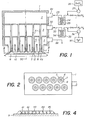
- the invention is illustrated by the appended drawing which represents a device making it possible to implement the method of the invention.
- This device is intended to coat a "float" glass plate with a uniform layer of transparent and electrically conductive Sn0 2 with very fine grains, its constructive elements being particularly designed to minimize the fouling of the projection members of the coating Sn0 2 .
- the invention may also be suitable for depositing other mineral coatings, for example layers of Ti0 2 , Si0 2 , Si (by decomposition, for example, of SiH 4 ), In 2 O 3 , Zr0 2 , Cr 2 O 3 , Fe 2 O 3 and NiO ain if their mixtures.
- the device given here by way of example and illustrated by FIGS. 1, 2 and 3 includes a box 1 containing two gas reagent supply chambers, 2 and 3, respectively for SnCl 4 and for water (the latter possibly containing other additives, for example HF ), and an evacuation chamber 4 of the gases from the reaction.
- the housing is equipped with two series of identical nozzles arranged in staggered rows (see fig. 2), these nozzles each comprising the following elements: a central duct 5 connected to the chamber 2, a coaxial nozzle 6 connected to the chamber 3 and a tubing or enveloping enclosure 7 of suction communicating with the evacuation chamber 4.
- the conduit 5 ends somewhat behind the orifice of the nozzle 6 which comprises a deflector 8 intended to cause the spreading, between the latter and the glass plate 9 to be coated, of the reaction gases emerging from the orifice of the nozzle, so that the zone of said plate located directly opposite of said deflector 8 is coated uniformly with the solid reaction product, in this case SnO 2 , the "float" glass plate 9 itself rests on rollers 10 which drive it in horizontal translation relative to the nozzles and perpendicularly at u drawing in fig. 1, this so that the coating is gradually and regularly deposited thereon.
- a deflector 8 intended to cause the spreading, between the latter and the glass plate 9 to be coated, of the reaction gases emerging from the orifice of the nozzle, so that the zone of said plate located directly opposite of said deflector 8 is coated uniformly with the solid reaction product, in this case SnO 2 , the "float" glass plate 9 itself rests on rollers 10 which drive it in horizontal translation relative to the nozzles and perpendicularly
- the conduit 5 contains a baffle of helical shape, in this case a coil spring 11, the presence of which constrains the current of gas descending in the duct 5 to take a rotation movement to the right.
- the coaxial nozzle 6 includes a spring 12 giving the gases which pass through it a levorotatory movement. The gases coming from the orifices of the nozzles 5 and 6 joining in the mouth 6a of the nozzle therefore meet approximately against the current (the angle of encounter approaches 180 °) which ensures an almost instantaneous mixing. reagents. It is understood that the springs 11 and 12 could be replaced by any other means of rotary deflection of the gases, fins for example.
- the device illustrated in the drawing also includes a controlled supply system for the reagents constituted by the following organs: an inlet pipe 22 entering the chamber 2 connected, as shown diagrammatically by the arrowed line 23 to an evaporator 24 in the form of a coil immersed in a liquid 25 heated to a suitable temperature to ensure the evaporation of SnCl 4 .
- This reagent, contained in a reservoir 26 is injected in a quantity measured by a metering ponpe 27 upstream of the evaporator 24 in the supply line 23. It should be noted that it is also possible to introduce a gas (but this optionally) carrier in line 23 as shown in the drawing.
- This carrier gas for example a mixture of N 2 and H 2 more or less dilutes the vapor of SnCl 4 and allows effective control of its flow rate in the nozzles of this device.
- the latter also comprises, as shown in the drawing, a water supply quite similar to that of SnCl 4 , this water supply comprising the inlet pipe 32, the supply line 33, the evaporator 34 heated by the liquid 35 and the metering pump 36 making it possible to measure the exact flow rate of water from the reservoir 37.
- the evacuation chamber 4 is connected, by a suction pipe represented by the arrow 38, to a conventional system d 'suction and depollution of gases not shown here.
- chambers 2 and 3 contain a system of baffles (known per se and not shown in the drawing) intended to distribute the pressure and the flow of gas uniformly in each nozzle of this device.
- baffles known per se and not shown in the drawing
- a first sinusoid 41 represents the profile of the trace (theoretical moreover because, in fact, this profile rather affects the shape of a series of crenals) constituted by the deposit from the first row of nozzles and by a second sinusoid 42, the profile of the trace of the deposition of the second row of nozzles.
- the shaded areas 43 represent the sum (by integration) of the deposits on the zones common to the two sinusoidal series of deposits and, obviously, this sum corresponds, as a physical entity, to the punctuated area 44 which, in some so, fills the "voids" existing between the crests of the sinusoids 41 and 42.
- the shape of the final deposit corresponds to the envelope curve 45, which demonstrates that the overall deposit obtained by the present device is regular and of practically constant thickness. . It is moreover possible, if one wishes to vary the degree of encroachment of one of the sets of traces on the other and if the operational scope of the set of nozzles is sufficient relative to the width of the glass plate , to slightly rotate the coating device around a fictitious vertical axis 50, all so as to offset laterally the traces of one of the rows of nozzles with respect to the other.
- the present device has been limited to two rows of five nozzles, it is easy to provide a greater number of these rows, for example 3, 4, 5 or more, this in order to reinforce the thickness of the overall deposit and any number of nozzles in each row.
- Fig. 5 shows a first variant of the nozzle of the invention.
- this variant comprises a central nozzle 55, a coaxial nozzle 56, a suction chamber 57 and deflector springs 61 and 62.
- the deflectors 8 of the nozzle of FIG. 3 are however replaced in the present variant by an annular pad 63 made of porous material, for example a ceramic or a sintered metal (Cu, Ni, Fe, etc.), housed at the end of an intermediate coaxial tube 64 connected to an additional gas supply chamber not shown in the drawing.
- the frustoconical shape of the tanpon makes it possible for the flow of a gas (a carrier gas) admitted by the tube 64 and passing through this tanpon to be distributed as a function of the load constituted by the porous material of this tanpon: lower at outside only towards the center. It will therefore be possible in this way to very effectively adjust the conditions of dispersion of the reaction gases at the outlet of the nozzle, the carrier gas coming from the nozzle 64 playing the role of an air cushion, the distribution of which (see arrows 65 of the drawing) acts on the distribution of the gaseous reaction medium between the outlet of the nozzle, the glass plate and the suction enclosure 57.
- This variant makes it possible to further improve the regularity and the homogeneity of the coating layer.
- Fig. 6 schematically represents the end of a second variant of the nozzle. It comprises, as in the cases already described, a central nozzle 71, a coaxial nozzle 72, a suction chamber 74 and springs 75 and 76 causing the flows descending from the nozzles 71 and 72 to rotate in opposite directions.
- the orifices of the two nozzles are at the same level and open into a frustoconical reaction zone 77, the oblique walls of which consist of an annular deflector 78 whose lower face is bevelled as indicated in the drawing. It results from the special shape of the zone 77 a regularization of the radial movement of the gases coming from the nozzle in the direction of the suction enclosure 74, phenomenon which contributes to ensuring a regular deposit on the plate 9 ..
- Fig. 7 shows the lower end of a third variant of the nozzle. This comprises a central nozzle 81 provided with a helical baffle 82 giving the gases descending in this nozzle a movement of rotation to the right as indicated by the arrow 83.
- the nozzle also comprises a coaxial nozzle 84 provided, at its end, with a frustoconical pad 85 of material permeable to gases.
- This material can be a ceramic or a sintered metal or a sheet of corrugated sheet, of copper for example, wound on itself so as to constitute a load with the passage of the gas passing through the nozzle 84, this charge serving to regulate and distribute, along a radial plane, the gases coming from said nozzle.
- the pad 85 can also consist of metallic bristles (gas permeable brush) crimped between the walls of the nozzles in a manner known per se, for example by an annular boss not shown in the drawing of the walls of the nozzle 84.
- the material of the pad (ceramic, rolled sheet, metallic bristles or glass fibers, etc.) must, of course, not be susceptible to attack by superheated steam; fiberglass, copper, nickel, bronze and stainless steel are suitable for this use.
- the pure water vapor or mixed with the inert carrier gas emerges vertically from the nozzle 84 (see arrows 86) and is struck approximately perpendicularly by the rotating gas coming from the nozzle 81. This is therefore a case of meets reactive fluxes at an angle close to 90 °. It will also be noted that, with the buffer 85 described here, the overall gas flow rate is approximately 3 to 4 times slower in the outer nozzle 84 than in the central nozzle 81.
- the operation of the present device is quite naturally deduced from the above description.
- the glass plate in fact constituted by a continuous ribbon of "float” glass, circulates at a suitable speed, for example, of the order of 5 to 25 m / min, driven by the rollers 10 and its temperature at the outlet. of the "float” oven is around 450-600 ° C.
- This glass ribbon circulates at a distance of the order of 1 to 5 mm from the outlet of the nozzles of this device.
- all these members are also kept at a sufficient temperature (120-200 °), the heating being ensured, either by means not shown but conventional (electric heating body, for example), or by direct radiation from the float glass ribbon.
- suction pressures (and of course the flow rates) will be higher than the supply pressures, so as to always ensure perfect evacuation of the reaction gases and avoid fouling of the deposition members.
- An apparatus conforming to the present description was used and it was used to coat with a transparent and electrically conductive layer of SnO 2 a strip of float glass with a width of 30 cm moving at the speed of 5 m / min, and brought to the temperature of 600 ° C.
- Constructive parameters of the nozzles nozzle walls, thickness: 0.1 mm; 0 of inner tube 5: 1.8 mm; ⁇ of the coaxial nozzle 6: 2.8 mm; useful surface of the outlet orifices of tubes 5 and 6: 3.1 mm 2 ; distance between the mouths of tubes 5 and 6: 1 mm; distance between glass and nozzles: 2 mm; ⁇ of the deflector 8: 10 mm; diameter of the suction chamber: 14 mm; distance between the nozzles (axis to axis): 15 mm; housing and nozzle temperature: 150 ° C.
- a layer of SnO 2 of 1 u was thus deposited on the glass ribbon, the transparency of which was 80% and the resistance R ⁇ of 3 ⁇ .
Landscapes
- Chemical & Material Sciences (AREA)
- Engineering & Computer Science (AREA)
- Materials Engineering (AREA)
- Chemical Kinetics & Catalysis (AREA)
- General Chemical & Material Sciences (AREA)
- Organic Chemistry (AREA)
- Geochemistry & Mineralogy (AREA)
- Life Sciences & Earth Sciences (AREA)
- Physics & Mathematics (AREA)
- Plasma & Fusion (AREA)
- Mechanical Engineering (AREA)
- Metallurgy (AREA)
- Chemical Vapour Deposition (AREA)
- Surface Treatment Of Glass (AREA)
Priority Applications (1)
| Application Number | Priority Date | Filing Date | Title |
|---|---|---|---|
| AT82810096T ATE14145T1 (de) | 1981-03-06 | 1982-03-04 | Verfahren zum ueberziehen eines substrates mit einem anorganischen oxid und vorrichtung zur anwendung dieses verfahrens. |
Applications Claiming Priority (2)
| Application Number | Priority Date | Filing Date | Title |
|---|---|---|---|
| CH1520/81 | 1981-03-06 | ||
| CH152081A CH640571A5 (fr) | 1981-03-06 | 1981-03-06 | Procede et dispositif pour deposer sur un substrat une couche de matiere minerale. |
Publications (2)
| Publication Number | Publication Date |
|---|---|
| EP0060221A1 true EP0060221A1 (de) | 1982-09-15 |
| EP0060221B1 EP0060221B1 (de) | 1985-07-03 |
Family
ID=4212358
Family Applications (1)
| Application Number | Title | Priority Date | Filing Date |
|---|---|---|---|
| EP82810096A Expired EP0060221B1 (de) | 1981-03-06 | 1982-03-04 | Verfahren zum Überziehen eines Substrates mit einem anorganischen Oxid und Vorrichtung zur Anwendung dieses Verfahrens |
Country Status (7)
| Country | Link |
|---|---|
| US (2) | US4476158A (de) |
| EP (1) | EP0060221B1 (de) |
| JP (1) | JPS58500173A (de) |
| AT (1) | ATE14145T1 (de) |
| CH (1) | CH640571A5 (de) |
| DE (1) | DE3264486D1 (de) |
| WO (1) | WO1982003093A1 (de) |
Cited By (1)
| Publication number | Priority date | Publication date | Assignee | Title |
|---|---|---|---|---|
| EP0450016A4 (en) * | 1989-10-17 | 1993-03-03 | Libbey-Owens-Ford Co. | Method for preparing vaporized reactants for chemical vapor deposition |
Families Citing this family (64)
| Publication number | Priority date | Publication date | Assignee | Title |
|---|---|---|---|---|
| US4524718A (en) * | 1982-11-22 | 1985-06-25 | Gordon Roy G | Reactor for continuous coating of glass |
| WO1985003460A1 (en) * | 1984-02-13 | 1985-08-15 | Schmitt Jerome J Iii | Method and apparatus for the gas jet deposition of conducting and dielectric thin solid films and products produced thereby |
| US4696837A (en) * | 1985-06-25 | 1987-09-29 | M&T Chemicals Inc. | Chemical vapor deposition method of producing fluorine-doped tin oxide coatings |
| US5391232A (en) * | 1985-12-26 | 1995-02-21 | Canon Kabushiki Kaisha | Device for forming a deposited film |
| US4747367A (en) * | 1986-06-12 | 1988-05-31 | Crystal Specialties, Inc. | Method and apparatus for producing a constant flow, constant pressure chemical vapor deposition |
| US4761269A (en) * | 1986-06-12 | 1988-08-02 | Crystal Specialties, Inc. | Apparatus for depositing material on a substrate |
| EP0254651B1 (de) * | 1986-06-28 | 1991-09-04 | Nihon Shinku Gijutsu Kabushiki Kaisha | Verfahren und Vorrichtung zum Beschichten unter Anwendung einer CVD-Beschichtungstechnik |
| US4775203A (en) * | 1987-02-13 | 1988-10-04 | General Electric Company | Optical scattering free metal oxide films and methods of making the same |
| US4880664A (en) * | 1987-08-31 | 1989-11-14 | Solarex Corporation | Method of depositing textured tin oxide |
| US4853257A (en) * | 1987-09-30 | 1989-08-01 | Ppg Industries, Inc. | Chemical vapor deposition of tin oxide on float glass in the tin bath |
| US4980204A (en) * | 1987-11-27 | 1990-12-25 | Fujitsu Limited | Metal organic chemical vapor deposition method with controlled gas flow rate |
| US5167718A (en) * | 1988-06-23 | 1992-12-01 | Jeffrey Stewart | Parylene deposition chamber and method of use |
| US6406544B1 (en) | 1988-06-23 | 2002-06-18 | Jeffrey Stewart | Parylene deposition chamber and method of use |
| US4945856A (en) * | 1988-06-23 | 1990-08-07 | Jeffrey Stewart | Parylene deposition chamber |
| US5078091A (en) * | 1988-06-23 | 1992-01-07 | Jeffrey Stewart | Parylene deposition chamber and method of use |
| US4951603A (en) * | 1988-09-12 | 1990-08-28 | Daidousanso Co., Ltd. | Apparatus for producing semiconductors |
| US4979465A (en) * | 1989-04-03 | 1990-12-25 | Daidousanso Co., Ltd. | Apparatus for producing semiconductors |
| JP2860505B2 (ja) * | 1991-02-25 | 1999-02-24 | シメトリックス コーポレーション | 材料蒸着装置 |
| US5124180A (en) * | 1991-03-11 | 1992-06-23 | Btu Engineering Corporation | Method for the formation of fluorine doped metal oxide films |
| US5268033A (en) * | 1991-07-01 | 1993-12-07 | Jeffrey Stewart | Table top parylene deposition chamber |
| US5422534A (en) * | 1992-11-18 | 1995-06-06 | General Electric Company | Tantala-silica interference filters and lamps using same |
| US5488833A (en) * | 1994-09-26 | 1996-02-06 | Stewart; Jeffrey | Tangential flow cold trap |
| US5741363A (en) * | 1996-03-22 | 1998-04-21 | Advanced Technology Materials, Inc. | Interiorly partitioned vapor injector for delivery of source reagent vapor mixtures for chemical vapor deposition |
| US5698262A (en) * | 1996-05-06 | 1997-12-16 | Libbey-Owens-Ford Co. | Method for forming tin oxide coating on glass |
| US6039812A (en) * | 1996-10-21 | 2000-03-21 | Abb Research Ltd. | Device for epitaxially growing objects and method for such a growth |
| US5888303A (en) * | 1997-04-07 | 1999-03-30 | R.E. Dixon Inc. | Gas inlet apparatus and method for chemical vapor deposition reactors |
| US5882725A (en) * | 1997-07-01 | 1999-03-16 | Para Tech Coating, Inc. | Parylene deposition chamber including eccentric part tumbler |
| US6527865B1 (en) | 1997-09-11 | 2003-03-04 | Applied Materials, Inc. | Temperature controlled gas feedthrough |
| US6258170B1 (en) * | 1997-09-11 | 2001-07-10 | Applied Materials, Inc. | Vaporization and deposition apparatus |
| DE19923591A1 (de) * | 1999-05-21 | 2000-11-23 | Fleissner Maschf Gmbh Co | Vorrichtung mit einem Düsenbalken zur Erzeugung von Flüssigkeitsstrahlen zur Strahlbeaufschlagung der Fasern einer Warenbahn |
| US7513815B2 (en) * | 1999-12-23 | 2009-04-07 | General Electric Company | Optimal silicon dioxide protection layer thickness for silver lamp reflector |
| US6382816B1 (en) | 1999-12-23 | 2002-05-07 | General Eectric Company | Protected coating for energy efficient lamp |
| US6544339B1 (en) | 2000-03-22 | 2003-04-08 | Micro C Technologies, Inc. | Rectilinear wedge geometry for optimal process control in chemical vapor deposition and rapid thermal processing |
| US6737224B2 (en) | 2001-04-17 | 2004-05-18 | Jeffrey Stewart | Method of preparing thin supported films by vacuum deposition |
| US6797108B2 (en) * | 2001-10-05 | 2004-09-28 | Applied Materials, Inc. | Apparatus and method for evenly flowing processing gas onto a semiconductor wafer |
| US7017514B1 (en) * | 2001-12-03 | 2006-03-28 | Novellus Systems, Inc. | Method and apparatus for plasma optimization in water processing |
| US7279432B2 (en) * | 2002-04-16 | 2007-10-09 | Applied Materials, Inc. | System and method for forming an integrated barrier layer |
| JP4338355B2 (ja) * | 2002-05-10 | 2009-10-07 | 東京エレクトロン株式会社 | プラズマ処理装置 |
| DE10239083B4 (de) * | 2002-08-26 | 2009-09-03 | Schott Ag | Vorrichtung zum Versorgen einer Prozesskammer mit fluiden Medien und deren Verwendung |
| US20050023983A1 (en) * | 2003-08-01 | 2005-02-03 | Rajasingh Israel | Optimal silicon dioxide protection layer thickness for silver lamp reflector |
| US7112541B2 (en) * | 2004-05-06 | 2006-09-26 | Applied Materials, Inc. | In-situ oxide capping after CVD low k deposition |
| TWI267405B (en) * | 2004-07-20 | 2006-12-01 | Sez Ag | Fluid discharging device |
| JP2006057173A (ja) * | 2004-08-24 | 2006-03-02 | Tohoku Pioneer Corp | 成膜源、真空成膜装置、有機elパネルの製造方法 |
| US7273823B2 (en) * | 2005-06-03 | 2007-09-25 | Applied Materials, Inc. | Situ oxide cap layer development |
| DE102005056322A1 (de) * | 2005-11-25 | 2007-06-06 | Aixtron Ag | VPE-Reaktor mit koaxial zueinander angeordneten Quellgasrohren |
| JP4767000B2 (ja) * | 2005-11-28 | 2011-09-07 | 日立造船株式会社 | 真空蒸着装置 |
| US20070227659A1 (en) * | 2006-03-31 | 2007-10-04 | Tokyo Electron Limited | Plasma etching apparatus |
| JP2008047869A (ja) * | 2006-06-13 | 2008-02-28 | Hokuriku Seikei Kogyo Kk | シャワープレート及びその製造方法、並びにそのシャワープレートを用いたプラズマ処理装置、プラズマ処理方法及び電子装置の製造方法 |
| JP5463536B2 (ja) * | 2006-07-20 | 2014-04-09 | 北陸成型工業株式会社 | シャワープレート及びその製造方法、並びにそのシャワープレートを用いたプラズマ処理装置、プラズマ処理方法及び電子装置の製造方法 |
| BRPI0716387A2 (pt) * | 2006-08-29 | 2013-01-01 | Pilkington Group Ltd E Arkema Inc | método de deposição de vapor quìmico para depositar um revestimento de óxido de zinco sobre um substrato |
| CN101547873A (zh) * | 2006-08-29 | 2009-09-30 | 皮尔金顿集团有限公司 | 制备低电阻率掺杂氧化锌涂层及由此制成的物件的方法 |
| US7740901B2 (en) * | 2006-09-08 | 2010-06-22 | Pilkington Group Limited | Low temperature method of making a zinc oxide coated article and the coated article made thereby |
| US7345414B1 (en) | 2006-10-04 | 2008-03-18 | General Electric Company | Lamp for night vision system |
| JP4990594B2 (ja) * | 2006-10-12 | 2012-08-01 | 東京エレクトロン株式会社 | ガス供給装置、ガス供給方法、薄膜形成装置の洗浄方法、薄膜形成方法及び薄膜形成装置 |
| JP5010234B2 (ja) | 2006-10-23 | 2012-08-29 | 北陸成型工業株式会社 | ガス放出孔部材を一体焼結したシャワープレートおよびその製造方法 |
| JP4954734B2 (ja) * | 2007-01-30 | 2012-06-20 | 東京エレクトロン株式会社 | 基板処理装置及びガス供給方法 |
| US8440259B2 (en) * | 2007-09-05 | 2013-05-14 | Intermolecular, Inc. | Vapor based combinatorial processing |
| DE102010056021B3 (de) * | 2010-12-23 | 2012-04-19 | Centrotherm Sitec Gmbh | Düsenanordnung und CVD-Reaktor |
| US8398773B2 (en) * | 2011-01-21 | 2013-03-19 | Asm International N.V. | Thermal processing furnace and liner for the same |
| US20130269612A1 (en) * | 2012-04-16 | 2013-10-17 | Hermes-Epitek Corporation | Gas Treatment Apparatus with Surrounding Spray Curtains |
| US9328419B2 (en) * | 2012-04-18 | 2016-05-03 | Hermes-Epitek Corporation | Gas treatment apparatus with surrounding spray curtains |
| US8827176B2 (en) * | 2012-07-05 | 2014-09-09 | James A. Browning | HVOF torch with fuel surrounding oxidizer |
| US9132436B2 (en) * | 2012-09-21 | 2015-09-15 | Applied Materials, Inc. | Chemical control features in wafer process equipment |
| US20230019430A1 (en) * | 2021-07-13 | 2023-01-19 | Changxin Memory Technologies, Inc. | Gas injector and diffusion furnace device |
Citations (7)
| Publication number | Priority date | Publication date | Assignee | Title |
|---|---|---|---|---|
| FR926438A (fr) * | 1946-04-09 | 1947-10-01 | Procédé et dispositif pour la pulvérisation de liquide | |
| FR1089640A (fr) * | 1953-09-18 | 1955-03-21 | Phillips & Pain Vermorel | Perfectionnements aux lances à jet pulvérisé pour la lutte contre l'incendie et autres applications |
| FR1518843A (fr) * | 1967-02-13 | 1968-03-29 | Radiotechnique Coprim Rtc | Dispositif pour le dépôt de couches minces sur des supports semi-conducteurs |
| US3511703A (en) * | 1963-09-20 | 1970-05-12 | Motorola Inc | Method for depositing mixed oxide films containing aluminum oxide |
| US3524590A (en) * | 1968-04-01 | 1970-08-18 | Gen Electric | Nozzle for a pyrolytic coating and deposition process |
| DD107723A1 (de) * | 1973-12-03 | 1974-08-12 | ||
| FR2348165A1 (fr) * | 1976-04-13 | 1977-11-10 | Bfg Glassgroup | Procede et dispositif pour le revetement par un metal ou un compose metallique d'une face d'un ruban de verre en deplacement longitudinal continu |
Family Cites Families (6)
| Publication number | Priority date | Publication date | Assignee | Title |
|---|---|---|---|---|
| US2526220A (en) * | 1947-07-18 | 1950-10-17 | Daniel And Florence Guggenheim | Spray nozzle |
| GB1282866A (en) * | 1968-08-16 | 1972-07-26 | Pilkington Brothers Ltd | Improvements in or relating to the production of glass having desired surface characteristics |
| US3642521A (en) * | 1969-10-27 | 1972-02-15 | Texas Instruments Inc | Production of metal oxides |
| US3850679A (en) * | 1972-12-15 | 1974-11-26 | Ppg Industries Inc | Chemical vapor deposition of coatings |
| JPS5916106Y2 (ja) * | 1978-06-20 | 1984-05-12 | 正博 武田 | 自給式混合装置 |
| IT1144219B (it) * | 1980-06-20 | 1986-10-29 | Bfg Glassgroup | Procedimento e dispositivo per formare un rivestimento di metallo o di un composto metallico |
-
1981
- 1981-03-06 CH CH152081A patent/CH640571A5/fr not_active IP Right Cessation
-
1982
- 1982-03-04 WO PCT/CH1982/000032 patent/WO1982003093A1/fr not_active Ceased
- 1982-03-04 AT AT82810096T patent/ATE14145T1/de not_active IP Right Cessation
- 1982-03-04 EP EP82810096A patent/EP0060221B1/de not_active Expired
- 1982-03-04 US US06/440,225 patent/US4476158A/en not_active Expired - Fee Related
- 1982-03-04 JP JP57500687A patent/JPS58500173A/ja active Pending
- 1982-03-04 DE DE8282810096T patent/DE3264486D1/de not_active Expired
-
1983
- 1983-12-21 US US06/550,938 patent/US4508054A/en not_active Expired - Fee Related
Patent Citations (7)
| Publication number | Priority date | Publication date | Assignee | Title |
|---|---|---|---|---|
| FR926438A (fr) * | 1946-04-09 | 1947-10-01 | Procédé et dispositif pour la pulvérisation de liquide | |
| FR1089640A (fr) * | 1953-09-18 | 1955-03-21 | Phillips & Pain Vermorel | Perfectionnements aux lances à jet pulvérisé pour la lutte contre l'incendie et autres applications |
| US3511703A (en) * | 1963-09-20 | 1970-05-12 | Motorola Inc | Method for depositing mixed oxide films containing aluminum oxide |
| FR1518843A (fr) * | 1967-02-13 | 1968-03-29 | Radiotechnique Coprim Rtc | Dispositif pour le dépôt de couches minces sur des supports semi-conducteurs |
| US3524590A (en) * | 1968-04-01 | 1970-08-18 | Gen Electric | Nozzle for a pyrolytic coating and deposition process |
| DD107723A1 (de) * | 1973-12-03 | 1974-08-12 | ||
| FR2348165A1 (fr) * | 1976-04-13 | 1977-11-10 | Bfg Glassgroup | Procede et dispositif pour le revetement par un metal ou un compose metallique d'une face d'un ruban de verre en deplacement longitudinal continu |
Cited By (1)
| Publication number | Priority date | Publication date | Assignee | Title |
|---|---|---|---|---|
| EP0450016A4 (en) * | 1989-10-17 | 1993-03-03 | Libbey-Owens-Ford Co. | Method for preparing vaporized reactants for chemical vapor deposition |
Also Published As
| Publication number | Publication date |
|---|---|
| US4508054A (en) | 1985-04-02 |
| CH640571A5 (fr) | 1984-01-13 |
| WO1982003093A1 (fr) | 1982-09-16 |
| US4476158A (en) | 1984-10-09 |
| EP0060221B1 (de) | 1985-07-03 |
| ATE14145T1 (de) | 1985-07-15 |
| JPS58500173A (ja) | 1983-02-03 |
| DE3264486D1 (en) | 1985-08-08 |
Similar Documents
| Publication | Publication Date | Title |
|---|---|---|
| EP0060221B1 (de) | Verfahren zum Überziehen eines Substrates mit einem anorganischen Oxid und Vorrichtung zur Anwendung dieses Verfahrens | |
| LU84539A1 (fr) | Installation pour deposer en continu,sur la surface d'un substrat porte a haute temperature,une couche d'une matiere solide | |
| CA2071147C (fr) | Technique de formation par pyrolyse en voie gazeuse d'un revetement essentiellement a base d'oxygene et de silicium | |
| EP0781257B1 (de) | Glasscheibe mit leitender und/oder gering strahlender beschichtung | |
| FI61859C (fi) | Saett att bilda ett enhetligt oeverdrag av metall eller en metallfoerening pao ytan av ett glasunderlag och anordning foeratt bilda ett dylikt oeverdrag | |
| CH650275A5 (fr) | Appareil pour realiser le depot reactif d'un revetement d'oxyde sur un substrat. | |
| CH687204A5 (fr) | Dispositif et procédé de formation d'un revêtement pyrolytique. | |
| FR2470517A1 (fr) | Procede et dispositif de revetement de pieces a l'aide d'un plasma | |
| FR2542636A1 (fr) | Procede et dispositif de distribution reguliere d'un solide pulverulent sur un substrat en vue de son revetement et substrat ainsi revetu | |
| FR2636078A1 (fr) | Procede et appareillage de revetement par depot chimique en phase vapeur pour la realisation de couches sur des substrats | |
| EP0006064B1 (de) | Vorrichtung zum gleichmässigen Verteilen eines pulverförmigen Stoffes durch eine longitudinale Spalte und Anwendungen dieser Vorrichtung | |
| EP0191258A1 (de) | Verfahren und Vorrichtung zum Dosieren von rieselfähigen Substanzen | |
| LU83446A1 (fr) | Procede de et dispositif destine a la formation d'un revetement de metal ou de compose metallique sur une face d'un ruban de verre | |
| CA1291376C (fr) | Procede de revetement d'un substrat tel un ruban de verre, par un produit pulverulent, et dispositif pour la mise en oeuvre de ce procede | |
| LU85393A1 (fr) | Procede et dispositif de formation d'un revetement de metal ou de compose metallique sur un ruban de verre chaud | |
| CH670447A5 (de) | ||
| LU85350A1 (fr) | Procede et dispositif de formation d'un revetement de compose metallique sur un substrat chaud en matiere vitreuse | |
| CH670817A5 (de) | ||
| EP0704249B1 (de) | Vorrichtung zur Verteilung pulverförmiger Feststoffe auf der Oberfläche eines Substrats zur Beschichtung dieses Substrates | |
| FR2477131A1 (fr) | Procede et dispositif destine a la formation d'un revetement de metal ou de compose metallique sur une face d'un substrat en verre | |
| EP1348039B1 (de) | Vorrichtung, in der eine operation durchgeführt wird, die die kontrolle der atmosphäre in einer kammer erfordert | |
| CH670818A5 (de) | ||
| FR2476063A1 (fr) | Procede et dispositif destine a la formation d'un revetement de metal ou de compose metallique sur une face d'un substrat en verre | |
| CN102824864B (zh) | 汽化混合装置 | |
| EP0499523A1 (de) | Düse mit angehobenem stromabwärts liegendem Absatz zur Beschichtung eines Glasbandes durch Pyrolyse eines Gasgemisches |
Legal Events
| Date | Code | Title | Description |
|---|---|---|---|
| PUAI | Public reference made under article 153(3) epc to a published international application that has entered the european phase |
Free format text: ORIGINAL CODE: 0009012 |
|
| AK | Designated contracting states |
Designated state(s): AT BE CH DE FR GB IT LU NL SE |
|
| 17P | Request for examination filed |
Effective date: 19830310 |
|
| ITF | It: translation for a ep patent filed | ||
| GRAA | (expected) grant |
Free format text: ORIGINAL CODE: 0009210 |
|
| AK | Designated contracting states |
Designated state(s): AT BE CH DE FR GB IT LI LU NL SE |
|
| PG25 | Lapsed in a contracting state [announced via postgrant information from national office to epo] |
Ref country code: NL Effective date: 19850703 Ref country code: AT Effective date: 19850703 |
|
| REF | Corresponds to: |
Ref document number: 14145 Country of ref document: AT Date of ref document: 19850715 Kind code of ref document: T |
|
| PG25 | Lapsed in a contracting state [announced via postgrant information from national office to epo] |
Ref country code: SE Effective date: 19850730 |
|
| REF | Corresponds to: |
Ref document number: 3264486 Country of ref document: DE Date of ref document: 19850808 |
|
| NLV1 | Nl: lapsed or annulled due to failure to fulfill the requirements of art. 29p and 29m of the patents act | ||
| PG25 | Lapsed in a contracting state [announced via postgrant information from national office to epo] |
Ref country code: LU Free format text: LAPSE BECAUSE OF NON-PAYMENT OF DUE FEES Effective date: 19860331 Ref country code: LI Effective date: 19860331 Ref country code: CH Effective date: 19860331 Ref country code: BE Effective date: 19860331 |
|
| PLBE | No opposition filed within time limit |
Free format text: ORIGINAL CODE: 0009261 |
|
| STAA | Information on the status of an ep patent application or granted ep patent |
Free format text: STATUS: NO OPPOSITION FILED WITHIN TIME LIMIT |
|
| 26N | No opposition filed | ||
| BERE | Be: lapsed |
Owner name: BATTELLE MEMORIAL INSTITUTE Effective date: 19860331 |
|
| GBPC | Gb: european patent ceased through non-payment of renewal fee | ||
| PG25 | Lapsed in a contracting state [announced via postgrant information from national office to epo] |
Ref country code: FR Free format text: LAPSE BECAUSE OF NON-PAYMENT OF DUE FEES Effective date: 19861128 |
|
| REG | Reference to a national code |
Ref country code: CH Ref legal event code: PL |
|
| PG25 | Lapsed in a contracting state [announced via postgrant information from national office to epo] |
Ref country code: DE Effective date: 19861202 |
|
| REG | Reference to a national code |
Ref country code: FR Ref legal event code: ST |
|
| PG25 | Lapsed in a contracting state [announced via postgrant information from national office to epo] |
Ref country code: GB Effective date: 19881121 |