EP0455843B1 - Rückblickapparat für Kraftfahrzeuge - Google Patents
Rückblickapparat für Kraftfahrzeuge Download PDFInfo
- Publication number
- EP0455843B1 EP0455843B1 EP90108536A EP90108536A EP0455843B1 EP 0455843 B1 EP0455843 B1 EP 0455843B1 EP 90108536 A EP90108536 A EP 90108536A EP 90108536 A EP90108536 A EP 90108536A EP 0455843 B1 EP0455843 B1 EP 0455843B1
- Authority
- EP
- European Patent Office
- Prior art keywords
- vehicle
- optical conduit
- opening
- hollow tube
- optical
- Prior art date
- Legal status (The legal status is an assumption and is not a legal conclusion. Google has not performed a legal analysis and makes no representation as to the accuracy of the status listed.)
- Expired - Lifetime
Links
- 230000003287 optical effect Effects 0.000 claims description 29
- 230000000007 visual effect Effects 0.000 description 9
- 231100001261 hazardous Toxicity 0.000 description 1
- 238000009434 installation Methods 0.000 description 1
Images


Classifications
-
- G—PHYSICS
- G02—OPTICS
- G02B—OPTICAL ELEMENTS, SYSTEMS OR APPARATUS
- G02B7/00—Mountings, adjusting means, or light-tight connections, for optical elements
- G02B7/02—Mountings, adjusting means, or light-tight connections, for optical elements for lenses
- G02B7/021—Mountings, adjusting means, or light-tight connections, for optical elements for lenses for more than one lens
-
- B—PERFORMING OPERATIONS; TRANSPORTING
- B60—VEHICLES IN GENERAL
- B60R—VEHICLES, VEHICLE FITTINGS, OR VEHICLE PARTS, NOT OTHERWISE PROVIDED FOR
- B60R1/00—Optical viewing arrangements; Real-time viewing arrangements for drivers or passengers using optical image capturing systems, e.g. cameras or video systems specially adapted for use in or on vehicles
- B60R1/10—Front-view mirror arrangements; Periscope arrangements, i.e. optical devices using combinations of mirrors, lenses, prisms or the like ; Other mirror arrangements giving a view from above or under the vehicle
Definitions
- This invention relates to an viewing means for an automotive vehicle.
- a conventional internal rear view mirror in a vehicle usually has a visual restriction, i.e., it cannot cover the area closely behind the rear bumper.
- This "BLIND" spot to the vision of a driver usually extends five meters or more of ground space beyond the rear bumper.
- Side mirrors on the door usually cannot provide a rear view behind the rear bumper at all.
- the existing of this "BLIND" spot makes driving reverse awkward or even hazardous.
- the present optical viewing means projects the final image at a convenient viewing position to the car driver and allows the driver to see the rear view readily without additional movement.
- a reflecting means and a reflecting mirror are provided to direct the final image to a location which is readily visible to the car driver.
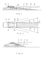
- FIGS.1 and 2 illustrate the rear visual coverage area of a typical automobile, including a "BLIND" spot shown by a shaded portion.
- This "BLIND" spot usually is not visible by a driver through conventional internal or external rear view mirrors.
- A1 and A2 show the visual boundary of an internal rear view mirror.
- 51,B1 and B2 show the visual boundary of the external rear view mirrors 52.
- the resultant "BLIND" spot behind the vehicle usually cover five meters or more of ground space from rear bumper 83 to boundary A1.
- FIG.3 illustrates the rear visual coverage area after adopting the present invention.
- the "BLIND" spot can be reduced to one meter or less.
- D1 and D2 depict the rear visual boundary of an embodiment which is placed in the rear trunk compartment.
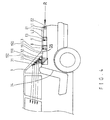
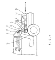
- FIG. 4 and 5 illustrate an embodiment of the present invention,preferably for vehicle with a rear trunk compartment 8,comprising an optical conduit 1, which is centrally and longitudinally affixed underneath a trunk lid 81, a multiple number of convex lenses L1, L2, L3 being disposed within said optical conduit 1, wherby the object lens L1 faces an rear opening 82 on a rear lateral wall of the trunk lid 81, a hollow tube 19 which is placed longitudinally under the rear window shelf 32 and having its rear opening 190 facing the front opening of the optical conduit 1. There is a top opening 192 on the hollow tube 19 which faces a rear window shelf opening 33 on the rear window shelf 32.
- an inclinded reflecting mirror 191 In the hollow tube 19 there is arranged an inclinded reflecting mirror 191 with its surface facing both the rear opening 190 and top opening 192.
- An inclined reflecting sheet 31 is attached to the rear window 3 and above rear the rear window shelf opening 33,whereby the real image I3 of the rear view R is formed in the optical conduit 1 and is then reflected twice on the reflecting mirror 191 and on the reflecting sheet 31, and eventually reaching the internal rear view mirror 51.
- a driver can look at mirror 51 to see the image I3 of rear view R, which is otherwise not visible.
- Figs.6, 7 and 8 illustrate another embodiment of the present invention, similar to that shown in figs. 4 and 5; except that instead of placing an optical conduit 1 underneath trunk lid 81 , two optical conduits 1 are disposed longitudinally along both side walls of a rear trunk compartment 8.
- the rear opening of the optical conduit 1 and the object lens L1 point toward an opening in the rear lamp combination 35 and thereby can capture rear view R to form a real and upright image I3.
- a hollow tube 19 connects the front end of optical conduit 1 and is located under a rear window shelf 32.
- An inclined reflecting mirror 191 is arranged inside hollow tube 19 with its surface facing the front opening of optical conduit 1 and a rear window shelf opening 33.
- a reflecting sheet 31 is attached to the rear window 3 above the rear window shelf opening 33.
Landscapes
- Physics & Mathematics (AREA)
- Engineering & Computer Science (AREA)
- General Physics & Mathematics (AREA)
- Optics & Photonics (AREA)
- Multimedia (AREA)
- Mechanical Engineering (AREA)
- Rear-View Mirror Devices That Are Mounted On The Exterior Of The Vehicle (AREA)
Claims (4)
- Blickapparat für ein Kraftfahrzeug, der einen Fahrer des Fahrzeuges in die Lage versetzt, eine rückwärtige Endansicht (R) hinter dem Fahrzeug zu sehen, mit wenigstens einer optischen Leitungsanordnung (1), einer Mehrzahl von konvexen Linsen (L1, L2, L3), die in der optischen Leitungsanordnung (1) angeordnet sind, einem hohlen Rohr (19) mit einem darin angeordneten Reflexionsspiegel (191) zum Reflektieren eines Bildes und Leiten desselben auf eine Reflexionseinrichtung (31), wobei die optische Leitungsanordnung (1) derart befestigbar ist, daß ein rückwärtiges Ende der optischen Leitungsanordnung (1) nach rückwärts gerichtet ist und ein vorderes Ende der optischen Leitungsanordnung (1) einer Öffnung des hohlen Rohres (19) zugewandt ist, wobei die konvexen Linsen (L1, L2, L3) so anordenbar sind, daß die rückwärtige Endansicht (R) des Fahrzeuges ein reelles und aufrechtes Bild (I3) in einem vorderen Bereich der optischen Leitungsanordnung (1) bildet, wobei das Bild (I3) zum Fahrer über das hohle Rohr (19) und die Reflexionseinrichtung (31) reflektiert wird, dadurch gekennzeichnet, daß das rückwärtige Ende der optischen Leitungsanordnung (1) einer hinteren Öffnung (82) eines hinteren Kofferraumes (8) des Fahrzeuges zugewandt ist, daß die Reflexionseinrichtung (31) an der Innenseite eines rückwärtigen Fensters (3) des Fahrzeuges und oberhalb einer Öffnung (43) der rückwärtigen Fensterablage des Fahrzeuges angeordnet ist und daß das hohle Rohr (19) unterhalb der Öffnung (33) der rückwärtigen Fensterablage angeordnet ist.
- Blickapparat nach Anspruch 1, dadurch gekennzeichnet, daß eine optische Leitungsanordnung (1) mittig und in Längsrichtung an einer Unterseite eines Bereiches eines rückwärtigen Kofferraumdeckels (81) derart befestigt ist, daß das rückwärtige Ende der optischen Leitungsanordnung (1) einer rückwärtigen Öffnung (82) des Kofferraumdeckels (81) zugewandt ist.
- Blickapparat nach Anspruch 1, dadurch gekennzeichnet, daß zwei optische Leitungsanordnungen (1) vorgesehen sind, von denen jede in Längsrichtung entlang einer Seitenwand des rückwärtigen Kofferraumes (8) derart befestigt ist, daß das rückwärtige Ende jeder optischen Leitungsanordnung (1) einer rückwärtigen Öffnung (82) des Kofferraumes (8) zugeordnet ist.
- Blickapparat nach Anspruch 3, dadurch gekennzeichnet, daß die rückwärtige Öffnung (82) eine Öffnung in der rückwärtigen Lampeneinheit (35) des Fahrzeuges ist.
Priority Applications (1)
| Application Number | Priority Date | Filing Date | Title |
|---|---|---|---|
| DE1990613673 DE69013673T2 (de) | 1990-05-07 | 1990-05-07 | Rückblickapparat für Kraftfahrzeuge. |
Applications Claiming Priority (1)
| Application Number | Priority Date | Filing Date | Title |
|---|---|---|---|
| US07/258,170 US4961637A (en) | 1988-10-14 | 1988-10-14 | Rear view lens apparatus for automotive vehicle |
Publications (2)
| Publication Number | Publication Date |
|---|---|
| EP0455843A1 EP0455843A1 (de) | 1991-11-13 |
| EP0455843B1 true EP0455843B1 (de) | 1994-10-26 |
Family
ID=22979402
Family Applications (1)
| Application Number | Title | Priority Date | Filing Date |
|---|---|---|---|
| EP90108536A Expired - Lifetime EP0455843B1 (de) | 1988-10-14 | 1990-05-07 | Rückblickapparat für Kraftfahrzeuge |
Country Status (2)
| Country | Link |
|---|---|
| US (1) | US4961637A (de) |
| EP (1) | EP0455843B1 (de) |
Families Citing this family (9)
| Publication number | Priority date | Publication date | Assignee | Title |
|---|---|---|---|---|
| DE4134198A1 (de) * | 1991-10-16 | 1993-04-22 | Bayerische Motoren Werke Ag | Rueckblickeinrichtung fuer kraftfahrzeuge |
| GB9124919D0 (en) * | 1991-11-22 | 1992-01-22 | Patel Sunil C | Viewing arrangement |
| WO1996015921A1 (en) * | 1994-11-22 | 1996-05-30 | Koo Ko | Rearview mirror system for vehicles |
| SE504492C2 (sv) * | 1995-04-03 | 1997-02-24 | Su Li | En backspegelenhet för ett fordon |
| US5774280A (en) * | 1995-08-25 | 1998-06-30 | Canon Kabushiki Kaisha | Lens barrel and optical apparatus |
| JPH09127576A (ja) * | 1995-11-01 | 1997-05-16 | Niles Parts Co Ltd | 多方向撮像カメラ装置 |
| FR2751430B1 (fr) * | 1996-07-16 | 1998-09-11 | Aerospatiale | Dispositif de suspension et de guidage en translation pour un appareil et appareil equipe d'un tel dispositif |
| JP4364900B2 (ja) * | 2006-12-26 | 2009-11-18 | 本田技研工業株式会社 | セダン型車両の後部車体構造 |
| CN117557660B (zh) * | 2024-01-09 | 2024-04-12 | 北京集度科技有限公司 | 数据处理方法、装置、电子设备以及车辆 |
Family Cites Families (14)
| Publication number | Priority date | Publication date | Assignee | Title |
|---|---|---|---|---|
| US1977019A (en) * | 1933-05-27 | 1934-10-16 | Frank L Smith | Rear vision device |
| GB473539A (en) * | 1936-04-16 | 1937-10-15 | Houghton Butcher Mfg Co Ltd | Improvements in and relating to viewing devices especially for aircraft |
| US2398354A (en) * | 1944-09-11 | 1946-04-16 | Dyron L Brinkley | Motor vehicle periscope |
| US2512792A (en) * | 1948-06-19 | 1950-06-27 | John J Delaney | Rear vision reflector tube for motor vehicles |
| FR1227476A (fr) * | 1959-03-23 | 1960-08-22 | Rétroviseur perfectionné | |
| US3280700A (en) * | 1962-12-06 | 1966-10-25 | Donnelly Mirrors Inc | Periscopic rear view system |
| GB1217223A (en) * | 1967-05-23 | 1970-12-31 | Cesare Morais | Rear-view optical system |
| US3809462A (en) * | 1972-05-12 | 1974-05-07 | Donnelly Mirrors Inc | View expanding and directing optical system |
| US3809461A (en) * | 1972-05-12 | 1974-05-07 | Donnelly Mirrors Inc | View expanding and directing optical system |
| DE2330275A1 (de) * | 1973-06-14 | 1975-01-09 | Werner Dr Ohl | Sicherheitseinrichtung, insbesondere fuer kraftfahrzeuge |
| FR2425959A1 (fr) * | 1978-05-17 | 1979-12-14 | Grandbarbe Norbert | Dispositif de controle optique des plages arriere ou avant non visibles par retroviseur pour les vehicules routiers ou de chantier |
| JPS5822831Y2 (ja) * | 1978-07-15 | 1983-05-16 | 岡村 誠 | 自動車用後方監視装置 |
| US4277804A (en) * | 1978-11-01 | 1981-07-07 | Elburn Robison | System for viewing the area rearwardly of a vehicle |
| JPS60213534A (ja) * | 1984-04-06 | 1985-10-25 | Makoto Okamura | 監視装置 |
-
1988
- 1988-10-14 US US07/258,170 patent/US4961637A/en not_active Expired - Fee Related
-
1990
- 1990-05-07 EP EP90108536A patent/EP0455843B1/de not_active Expired - Lifetime
Also Published As
| Publication number | Publication date |
|---|---|
| US4961637A (en) | 1990-10-09 |
| EP0455843A1 (de) | 1991-11-13 |
Similar Documents
| Publication | Publication Date | Title |
|---|---|---|
| US4968124A (en) | Vehicle viewing system | |
| US5619370A (en) | Optical system for viewing a remote location | |
| CN100565273C (zh) | 车辆防眩目系统 | |
| US4277804A (en) | System for viewing the area rearwardly of a vehicle | |
| EP0455843B1 (de) | Rückblickapparat für Kraftfahrzeuge | |
| EP0846597A2 (de) | Rückblickspiegel- Baugruppe für Kraftfahrzeuge | |
| ITMI922004A0 (it) | Parabrezza automobilistico per un sistema di visualizzazione a testa eretta | |
| GB2240855A (en) | Automotive reflection type display apparatus | |
| EP0751041A2 (de) | Vorrichtung zum Überprüfen des seitlichen Sichtfeldes am vorder oder hinter Ende eines Fahrzeuges | |
| FR2698060B1 (fr) | Dispositif d'essuie-glace pour l'essuyage d'une vitre portée par un panneau ouvrant d'un véhicule automobile. | |
| GB2302071A (en) | Non-distorting blind spot mirror | |
| US3394978A (en) | Dual side split rearview reflecting system | |
| US5127357A (en) | Garage parking guide | |
| US4120566A (en) | Rearview apparatus for vehicles | |
| US4439021A (en) | Motor vehicle rear viewing system | |
| US6935758B2 (en) | Driver observation system | |
| US7365300B2 (en) | Rear vision system | |
| US4435044A (en) | Rear view mirror assembly | |
| US5099229A (en) | Indication display unit for a vehicle | |
| FR2727918B1 (fr) | Dispositif d'essuie-glace pour vehicule automobile muni d'un capot d'habillage | |
| KR0135240Y1 (ko) | 차량의 후방사각지대 감지장치 | |
| US6587285B2 (en) | Vehicle periphery visual confirmation apparatus | |
| US5986822A (en) | Rearview mirror for motor vehicle, especially car or bus | |
| JPH05301539A (ja) | 自動車の補助ミラー | |
| GB2258199A (en) | A viewing device for a vehicle |
Legal Events
| Date | Code | Title | Description |
|---|---|---|---|
| PUAI | Public reference made under article 153(3) epc to a published international application that has entered the european phase |
Free format text: ORIGINAL CODE: 0009012 |
|
| AK | Designated contracting states |
Kind code of ref document: A1 Designated state(s): DE FR GB IT |
|
| 17P | Request for examination filed |
Effective date: 19920508 |
|
| 17Q | First examination report despatched |
Effective date: 19930107 |
|
| GRAA | (expected) grant |
Free format text: ORIGINAL CODE: 0009210 |
|
| AK | Designated contracting states |
Kind code of ref document: B1 Designated state(s): DE FR GB IT |
|
| ITF | It: translation for a ep patent filed | ||
| REF | Corresponds to: |
Ref document number: 69013673 Country of ref document: DE Date of ref document: 19941201 |
|
| ET | Fr: translation filed | ||
| PGFP | Annual fee paid to national office [announced via postgrant information from national office to epo] |
Ref country code: FR Payment date: 19950517 Year of fee payment: 6 |
|
| PGFP | Annual fee paid to national office [announced via postgrant information from national office to epo] |
Ref country code: GB Payment date: 19950522 Year of fee payment: 6 |
|
| PGFP | Annual fee paid to national office [announced via postgrant information from national office to epo] |
Ref country code: DE Payment date: 19950722 Year of fee payment: 6 |
|
| PLBE | No opposition filed within time limit |
Free format text: ORIGINAL CODE: 0009261 |
|
| STAA | Information on the status of an ep patent application or granted ep patent |
Free format text: STATUS: NO OPPOSITION FILED WITHIN TIME LIMIT |
|
| 26N | No opposition filed | ||
| PG25 | Lapsed in a contracting state [announced via postgrant information from national office to epo] |
Ref country code: GB Effective date: 19960507 |
|
| GBPC | Gb: european patent ceased through non-payment of renewal fee |
Effective date: 19960507 |
|
| PG25 | Lapsed in a contracting state [announced via postgrant information from national office to epo] |
Ref country code: FR Effective date: 19970131 |
|
| PG25 | Lapsed in a contracting state [announced via postgrant information from national office to epo] |
Ref country code: DE Effective date: 19970201 |
|
| REG | Reference to a national code |
Ref country code: FR Ref legal event code: ST |
|
| PG25 | Lapsed in a contracting state [announced via postgrant information from national office to epo] |
Ref country code: IT Free format text: LAPSE BECAUSE OF NON-PAYMENT OF DUE FEES;WARNING: LAPSES OF ITALIAN PATENTS WITH EFFECTIVE DATE BEFORE 2007 MAY HAVE OCCURRED AT ANY TIME BEFORE 2007. THE CORRECT EFFECTIVE DATE MAY BE DIFFERENT FROM THE ONE RECORDED. Effective date: 20050507 |