EP0455883A2 - Dispositif de réglage pour un papillon des gaz - Google Patents
Dispositif de réglage pour un papillon des gaz Download PDFInfo
- Publication number
- EP0455883A2 EP0455883A2 EP90124833A EP90124833A EP0455883A2 EP 0455883 A2 EP0455883 A2 EP 0455883A2 EP 90124833 A EP90124833 A EP 90124833A EP 90124833 A EP90124833 A EP 90124833A EP 0455883 A2 EP0455883 A2 EP 0455883A2
- Authority
- EP
- European Patent Office
- Prior art keywords
- throttle valve
- gear
- valve shaft
- driver
- adjusting device
- Prior art date
- Legal status (The legal status is an assumption and is not a legal conclusion. Google has not performed a legal analysis and makes no representation as to the accuracy of the status listed.)
- Granted
Links
Images

Classifications
-
- B—PERFORMING OPERATIONS; TRANSPORTING
- B60—VEHICLES IN GENERAL
- B60K—ARRANGEMENT OR MOUNTING OF PROPULSION UNITS OR OF TRANSMISSIONS IN VEHICLES; ARRANGEMENT OR MOUNTING OF PLURAL DIVERSE PRIME-MOVERS IN VEHICLES; AUXILIARY DRIVES FOR VEHICLES; INSTRUMENTATION OR DASHBOARDS FOR VEHICLES; ARRANGEMENTS IN CONNECTION WITH COOLING, AIR INTAKE, GAS EXHAUST OR FUEL SUPPLY OF PROPULSION UNITS IN VEHICLES
- B60K28/00—Safety devices for propulsion-unit control, specially adapted for, or arranged in, vehicles, e.g. preventing fuel supply or ignition in the event of potentially dangerous conditions
- B60K28/10—Safety devices for propulsion-unit control, specially adapted for, or arranged in, vehicles, e.g. preventing fuel supply or ignition in the event of potentially dangerous conditions responsive to conditions relating to the vehicle
- B60K28/16—Safety devices for propulsion-unit control, specially adapted for, or arranged in, vehicles, e.g. preventing fuel supply or ignition in the event of potentially dangerous conditions responsive to conditions relating to the vehicle responsive to, or preventing, spinning or skidding of wheels
-
- F—MECHANICAL ENGINEERING; LIGHTING; HEATING; WEAPONS; BLASTING
- F02—COMBUSTION ENGINES; HOT-GAS OR COMBUSTION-PRODUCT ENGINE PLANTS
- F02D—CONTROLLING COMBUSTION ENGINES
- F02D11/00—Arrangements for, or adaptations to, non-automatic engine control initiation means, e.g. operator initiated
- F02D11/06—Arrangements for, or adaptations to, non-automatic engine control initiation means, e.g. operator initiated characterised by non-mechanical control linkages, e.g. fluid control linkages or by control linkages with power drive or assistance
- F02D11/10—Arrangements for, or adaptations to, non-automatic engine control initiation means, e.g. operator initiated characterised by non-mechanical control linkages, e.g. fluid control linkages or by control linkages with power drive or assistance of the electric type
-
- F—MECHANICAL ENGINEERING; LIGHTING; HEATING; WEAPONS; BLASTING
- F02—COMBUSTION ENGINES; HOT-GAS OR COMBUSTION-PRODUCT ENGINE PLANTS
- F02D—CONTROLLING COMBUSTION ENGINES
- F02D11/00—Arrangements for, or adaptations to, non-automatic engine control initiation means, e.g. operator initiated
- F02D11/06—Arrangements for, or adaptations to, non-automatic engine control initiation means, e.g. operator initiated characterised by non-mechanical control linkages, e.g. fluid control linkages or by control linkages with power drive or assistance
- F02D11/10—Arrangements for, or adaptations to, non-automatic engine control initiation means, e.g. operator initiated characterised by non-mechanical control linkages, e.g. fluid control linkages or by control linkages with power drive or assistance of the electric type
- F02D2011/101—Arrangements for, or adaptations to, non-automatic engine control initiation means, e.g. operator initiated characterised by non-mechanical control linkages, e.g. fluid control linkages or by control linkages with power drive or assistance of the electric type characterised by the means for actuating the throttles
- F02D2011/103—Arrangements for, or adaptations to, non-automatic engine control initiation means, e.g. operator initiated characterised by non-mechanical control linkages, e.g. fluid control linkages or by control linkages with power drive or assistance of the electric type characterised by the means for actuating the throttles at least one throttle being alternatively mechanically linked to the pedal or moved by an electric actuator
Definitions
- Load adjustment device with a throttle valve determining the performance of an internal combustion engine, which is connected in a rotationally fixed manner to a throttle valve shaft mounted in the throttle valve housing, a control element acting on the throttle valve shaft, which cooperates with a driver coupled to an accelerator pedal and can be controlled by means of an electric motor interacting with an electronic control device and controls the position of the throttle valve in the idling range (LL min -LL max ) via a gearbox.
- load adjustment devices Of particular importance in load adjustment devices is the mastery of the load state of idling, in which only one of the internal combustion engines minimum power is given, but this may be the case for motor vehicles, which may require high performance, such as blowers, rear window heating, air conditioning, etc. In order to take these potential performance requirements into account, it is necessary to regulate the load adjustment device between a minimum and a maximum idle position . If the control fails, the actuator or control element must be in an idle emergency position.
- load adjustment devices of the type mentioned are generally used where the accelerator pedal and the actuator are electronically linked.
- the accelerator pedal is coupled to the driver and this to the control element.
- a setpoint detection element cooperating with this and an actual value detection element interacting with it and acting on the electric actuator are provided, the electric actuator being controllable by the electronic control device as a function of the detected values.
- the electrical link between the accelerator pedal and the actuator with the electronic control device connected in between enables the accelerator pedal and the driver coupled to it to be used to set predetermined setpoint positions in relation to the actual values represented by the position of the control element and actuator and to check for existing or missing plausibility conditions , so that in the presence or absence of certain plausibility conditions there is the possibility of actuation via the electronic control device of the electric actuator to have a corrective effect on the actuator, which can be designed, for example, as a throttle valve or injection pump.
- an intervention by the electronic control device to avoid wheel slip when starting due to excessive power input by the accelerator pedal can be provided.
- Other automatic interventions in the load adjustment device are conceivable, for example, in the case of automatic switching operations of a transmission, a speed limit control or the previously discussed idle control of the internal combustion engine.
- the invention has for its object to provide a load adjustment device of the type mentioned, which ensures a safe and accurate control of the internal combustion engine over the entire idling range and a response to the anti-slip control device with a structurally simple design, the individual components in a small space should be accommodated.
- the object is achieved in that, in addition to the one gear, a further gear is provided which is effective above the idling range (LL max ). Due to the configuration of the load adjustment device according to the invention, regulation can be carried out upwards (LL max ) and downwards (LL min ) over the entire idle control range by means of a single actuator. It is also possible to ensure that the internal combustion engine is shut down by means of the additional gear in the anti-slip control area (ASR).
- ASR anti-slip control area
- the further gear has a freewheel device.
- the gearbox having the freewheel device adjusts the throttle valve shaft in the direction of closing.
- the further transmission consists of an output disk arranged on the output shaft of the electric motor, which continuously engages with a drive disk arranged on the throttle valve shaft, which is equipped with the freewheel device.
- the freewheel device consists of a slot guide running concentrically to the throttle valve shaft, in which a linkage is received, which is connected non-rotatably directly or indirectly to the throttle valve shaft. This also ensures that the internal combustion engine is automatically regulated in the event of an anti-slip control, even if the driver continues to accelerate using the accelerator pedal. Due to the slot guide and the linkage accommodated in it, an adjustment of the throttle valve shaft can only be ensured in the direction of closing the throttle valve.
- another transmission gear can also be provided in an advantageous manner.
- the driven disk is rotatably connected to the driven shaft of the electric motor and the drive disk for driving the throttle valve shaft is rotatably mounted thereon.
- the first gear having the freewheel device is followed by the second gear, which has a cam disc arranged on the output shaft of the electric motor, in which a groove in the form of an Archimedes spiral is arranged, in which a cam connected to the handlebar is guided is.
- This gear is suitable for very large translations and can still be accommodated in the smallest space.
- the link which is operatively connected to the cam disk is rotatably mounted on the throttle valve shaft and with it via a driver in the direction Opening the throttle valve is effectively connected. It is also advantageous that the accelerator pedal is operatively connected to the throttle valve shaft via a driver and a freewheel hook.
- the freewheel hook is arranged either on the driver or on the throttle valve shaft and has two drivers arranged at a distance from one another, between which a lever is arranged either on the throttle valve shaft or on the driver, which lever is arranged between a lower one Idle position (LL min ) and an upper idle position (LL max ) is adjustable, whereby the lever is brought into contact with the first driver in the direction of full load operation and with a second spring against the driver in the direction of the lower idle position (LL min ) .
- the first gear having the freewheel device acts on the throttle valve only in the closing direction and the second gear having the cam disc only acts on the throttle valve in the opening direction. It is also advantageous that the handlebar can be preloaded into the emergency running position by means of an emergency running spring. This ensures that if the electric motor or the control device fails, the throttle valve is automatically set to idle operation.
- the driver connected to the accelerator pedal between a first stop in the idling direction (LL) and a second stop in full load direction (VL) is adjustable.
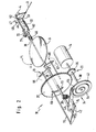
- the parts shown in the frame 18 according to Figure 1 form an actuator or a load adjustment device 10, which are combined in one unit.
- the load adjustment device 10 includes a servomotor or electric motor 14, which is connected to a throttle valve shaft 36 and a throttle valve 9 by means of a first gear 33, only schematically indicated, a freewheel device 69, a linkage 70 and a second gear 34 and a driver 42 .
- the actuating forces of the electric motor 14 are transmitted to the throttle valve 9 via the gears 33, 34, and an adjustment to the desired position is thereby brought about.
- the load adjustment device 10 can be adjusted via an accelerator pedal 1, a lever 2 and an accelerator cable 3, the lever 2 being shifted between an idle stop (LL) and a full load stop (VL) by actuating the accelerator pedal 1, and the accelerator cable 3 is biased by a return spring 5 in the idle direction (LL).
- the accelerator pedal 1 is connected to a driver 4 by means of an accelerator cable 3, so that when the accelerator pedal 1 is actuated, the driver 4 is displaced in the direction of the full load stop (VL).
- At least one return spring 6 is connected to the driver 4, which prestresses it in the idling direction (LL). As long as the throttle cable 3 is not acted upon, the driver 4 rests against the idling stop (LL) assigned to it.
- the driver 4 interacts via a lever 52 with a freewheel hook 47 which, according to the invention, consists of a bushing 62 pivotably mounted on the throttle valve shaft 36 with two spaced drivers 49, 51, which form a recess in which the lever 52 is received.
- the freewheel hook 47 forms a first control element part 8a (see FIG. 1).
- the control element part 8a corresponds to the bushing 62 and the throttle valve shaft 36 in FIG. 2. It is also possible to fasten the freewheel hook 47 to the driver 4 and the lever 52 to the bushing 62.
- the freewheel hook 47 is pulled in the idling direction (LL min ) by means of the spring 22, so that the driver 51 provided on the bush 62 is pulled against the lever 52 provided on the driver 4, the spring 22 mainly ensuring that the lever 43 and and the stop 74 are brought into contact.
- Another spring 46 provided on the throttle valve shaft 36 causes the throttle valve shaft 36 and thus the throttle valve 9 to be constantly pressed against a stop.
- a driver 72 is provided on the bushing 62 and a lever 71 is provided on the throttle valve shaft 36.
- the lever 71 of the throttle valve shaft 36 is pressed against the driver 72 by means of the spring 46 and the throttle valve 36 is thus held in abutment.
- the throttle valve 9 which then has assumed a position outside the idle control range, is pivoted back in the closing direction to the position LL min , as will be explained in more detail below.
- the load adjustment device 10 has a second control element part 8b which is designed as a linkage 70 of a transmission 34 and which is drive-connected to the transmission 34 and to the electric motor 14.
- a translation of the servomotor movement takes place by means of a gear 34, which is described in more detail below in terms of its structure and its function.
- a third control element part 8c designed as a freewheel device 69 is provided, which can also be coupled to the electric motor 14 via a further or the first gear 33.
- the electric motor 14 has an output shaft 38 on which an output disk or a pinion 35 is arranged in a rotationally fixed manner, which serves to adjust the throttle valve shaft 36 and for this purpose is drive-connected to a drive disk.
- the drive pulley 37 is equipped with a freewheel device 69, which consists of a slot guide 73 arranged concentrically to the throttle valve shaft 36, in which the linkage 70 running parallel to the throttle valve shaft 36 is received.
- a driver 42 is arranged in a rotationally fixed manner, which at one end can be brought into contact with the linkage 70 at the other end by means of a stop 74 against the underside of a link 43 which is freely pivotable on the throttle valve shaft 36.
- the handlebar 43 is assigned an emergency-running spring 20, which in case of failure of the electric motor 14 or other control devices the handlebar 43, the driver 42, the throttle valve shaft 36, and thus the throttle valve 9 is shifted into the neutral position not.
- the electric motor 14 is permanently connected indirectly to the throttle valve shaft 36 via the first and the second gear 33, 34.
- the second gear 34 consists of a cam 41 arranged on the output shaft 38 and the with this link 43 in drive connection.
- the link 43 has a cam 55 at its end opposite the linkage 7o. This is received in a groove 54 provided in a cam disk 41.
- the groove 54 has the shape of an Archimedes spiral and can advantageously extend over an angle of a total of 720 degrees, so that within two revolutions of the electric motor 14 an adjustment of the handlebar 43 and thus an adjustment of the throttle valve shaft 36 in the idle control range between LL min and LL max only in the direction of opening the throttle valve 9.
- the second gear 34 has the advantage that large gear ratios are possible in a simple manner, for example 1:30 to 1:40 and more.
- the output shaft 38 of the electric motor 14 is rotated by 720 o .
- the emergency running spring 20 ensures that in the event of a defect in an electronic control device 17 or the electric motor 14, the resistance moments of the electric motor 14 or the transmission parts are overcome and the throttle valve 9 is returned to the idling emergency position (LL not ).
- the actual value detection device 19 of the throttle valve 9 is advantageously mounted in the area of the pivotable linkage 70, while the setpoint value detection device 65 is provided in the area of the drive disk 37.
- the two gears 33, 34 are matched to one another in such a way that the first gearing 33 is only above the idle control range, i.e. in the part-load or full-load control range of the internal combustion engine.
- the throttle valve shaft 36 is preloaded with the associated throttle valve 9 in the direction of the minimal idling position (LL min ) by means of the spring 22.
- the first control element part 8a can also be brought into contact with the lever 52 with its freewheel hook 47 and the associated driver 51, the spring 22 mainly ensuring that the driver 42 with its stop 74 on the handlebar 43 is present.
- the throttle valve shaft 36 is moved outside the idle control range via the driver 51. Part-load or full-load operation, operated.
- the lever 71 bears against the driver 72, as already explained. Furthermore, the throttle valve shaft 36 is operatively connected via the linkage 70 to the first gear 33 and via the driver 42 to the link 43 of the second gear 34.
- the actuator shown in Figure 1 is shown in the idle min position. From Figure 1 it can also be seen that the linkage 70 acts on the throttle valve shaft 36 only in the closing direction, so that when the electric motor 14 is switched on, the throttle valve shaft 36 is only adjusted in the direction of idle position LL min via the first gear 33.
- the electronic control device 17 which contains conditioning, logic and control circuits, is indicated schematically.
- the control device 17 stores values for vehicle adaptation and processes the digital or digitized values of various input variables, which then regulate the desired position of the throttle valve 9 via an analog part.
- the electronic control device 17 interacts with the actual value detection device 19 belonging to the control element parts 8a, 8b and with the setpoint detection device 65 assigned to the gear 33 and determining the respective position of the drive pulley 37 and thus the throttle valve 9.
- a potentiometer 66 is assigned to the first actual value detection device 19 and a second potentiometer 67 to the setpoint value detection device 65.
- the control device 17 has the task of all input signals, e.g. Speed to be recorded by means of the potentiometer 66, 67 (FIG. 2) and compared with one another. If, for example, the vehicle speed deviates from the setpoint, the actuator is activated until the specified speed is reached.
- Speed e.g. Speed to be recorded by means of the potentiometer 66, 67 (FIG. 2) and compared with one another. If, for example, the vehicle speed deviates from the setpoint, the actuator is activated until the specified speed is reached.
- the electronic control device 17 also detects signals via an idle contact 68, which is activated by the driver 4, when the latter contacts the idle stop (LL) assigned to it System comes to drive the electric motor 14 only for the anti-slip control (ASR) outside the idle control range.
- an idle contact 68 which is activated by the driver 4, when the latter contacts the idle stop (LL) assigned to it System comes to drive the electric motor 14 only for the anti-slip control (ASR) outside the idle control range.
- the electronic control device 17 serves the purpose of building up a safety logic relating to the control of the first and second control element parts 8a, 8b. Once the electronic control device 17 or the electric motor 14 is no longer working properly, the throttle 9 is moved by the prestressed in the direction of maximum idle position the spring 22 in the idle position not (LL not).
- regulation can be carried out upwards (LLmax) and downwards (LL min ) over the entire idling range by means of a single actuator. Furthermore, it is possible to ensure that the internal combustion engine is shut down in the anti-slip control case (ASR) by means of the second gear 34 outside the idling control range.
- ASR anti-slip control case
- ASR anti-slip rule
- Signals are also detected by the electronic control device 17 via an idle contact 68, which is deactivated by the driver 4 or activated by the control element part 8a.
Landscapes
- Engineering & Computer Science (AREA)
- Chemical & Material Sciences (AREA)
- Combustion & Propulsion (AREA)
- Mechanical Engineering (AREA)
- Transportation (AREA)
- General Engineering & Computer Science (AREA)
- Control Of Throttle Valves Provided In The Intake System Or In The Exhaust System (AREA)
Applications Claiming Priority (2)
| Application Number | Priority Date | Filing Date | Title |
|---|---|---|---|
| DE4014556 | 1990-05-07 | ||
| DE4014556A DE4014556A1 (de) | 1990-05-07 | 1990-05-07 | Lastverstelleinrichtung |
Publications (3)
| Publication Number | Publication Date |
|---|---|
| EP0455883A2 true EP0455883A2 (fr) | 1991-11-13 |
| EP0455883A3 EP0455883A3 (en) | 1992-02-26 |
| EP0455883B1 EP0455883B1 (fr) | 1994-08-03 |
Family
ID=6405845
Family Applications (1)
| Application Number | Title | Priority Date | Filing Date |
|---|---|---|---|
| EP90124833A Expired - Lifetime EP0455883B1 (fr) | 1990-05-07 | 1990-12-19 | Dispositif de réglage pour un papillon des gaz |
Country Status (2)
| Country | Link |
|---|---|
| EP (1) | EP0455883B1 (fr) |
| DE (2) | DE4014556A1 (fr) |
Cited By (1)
| Publication number | Priority date | Publication date | Assignee | Title |
|---|---|---|---|---|
| EP0810359A3 (fr) * | 1996-06-01 | 1998-05-06 | Mannesmann VDO AG | Dispositif de commande de charge |
Family Cites Families (5)
| Publication number | Priority date | Publication date | Assignee | Title |
|---|---|---|---|---|
| EP0030022B1 (fr) * | 1979-11-30 | 1984-09-19 | Yamaha Hatsudoki Kabushiki Kaisha | Dispositif de commande de papillon pour moteur |
| US4411231A (en) * | 1982-04-16 | 1983-10-25 | Ford Motor Company | Carburetor throttle valve actuator |
| US4526060A (en) * | 1982-09-28 | 1985-07-02 | Ford Motor Company | Carburetor throttle valve actuator |
| DE3641244C3 (de) * | 1986-12-03 | 1995-02-23 | Vdo Schindling | Anordnung für ein Kraftfahrzeug |
| DE3900437C1 (fr) * | 1989-01-10 | 1989-11-16 | Vdo Adolf Schindling Ag, 6000 Frankfurt, De |
-
1990
- 1990-05-07 DE DE4014556A patent/DE4014556A1/de not_active Withdrawn
- 1990-12-19 EP EP90124833A patent/EP0455883B1/fr not_active Expired - Lifetime
- 1990-12-19 DE DE59006707T patent/DE59006707D1/de not_active Expired - Fee Related
Cited By (1)
| Publication number | Priority date | Publication date | Assignee | Title |
|---|---|---|---|---|
| EP0810359A3 (fr) * | 1996-06-01 | 1998-05-06 | Mannesmann VDO AG | Dispositif de commande de charge |
Also Published As
| Publication number | Publication date |
|---|---|
| DE4014556A1 (de) | 1991-11-14 |
| EP0455883B1 (fr) | 1994-08-03 |
| DE59006707D1 (de) | 1994-09-08 |
| EP0455883A3 (en) | 1992-02-26 |
Similar Documents
| Publication | Publication Date | Title |
|---|---|---|
| EP0389649B1 (fr) | Papillon d'accélérateur | |
| DE4313993C2 (de) | Leistungsübertragungs-Steuervorrichtung für ein Fahrzeug mit einem Verbrennungsmotor | |
| DE69103002T2 (de) | Drosselklappe. | |
| DE3927004A1 (de) | Lastverstelleinrichtung | |
| EP0413082B1 (fr) | Dispositif de réglage de charge | |
| DE3108579A1 (de) | Vorrichtung zum regeln der leerlaufdrehzahl einer brennkraftmaschine | |
| EP0208222A2 (fr) | Dispositif de commande de la vitesse de ralenti pour moteur à allumage commandé, plus particulièrement pour véhicule | |
| EP0269780B1 (fr) | Dispositif de transmission de la position d'un élément de commande actionnable par le conducteur d'un véhicule | |
| DE4034575A1 (de) | Lastverstelleinrichtung | |
| EP0456904B1 (fr) | Dispositif de réglage de la puissance | |
| EP0378737B1 (fr) | Dispositif de réglage de la charge | |
| EP0378736B1 (fr) | Dispositif de réglage de la charge | |
| WO1999010642A1 (fr) | Dispositif d'ajustement de charge | |
| EP0455882B1 (fr) | Dispositif de réglage pour un papillon des gaz | |
| EP0455883A2 (fr) | Dispositif de réglage pour un papillon des gaz | |
| EP0455877B1 (fr) | Dispositif de réglage de charge | |
| DE4005905A1 (de) | Elektromotorisch betaetigbare leistungssteuervorrichtung einer brennkraftmaschine | |
| EP0570623A2 (fr) | Dispositif d'ajustement de papillon d'admission | |
| EP0540811B1 (fr) | Dispositif pour le positionnement d'un clapet d'étranglement | |
| DE4033802A1 (de) | Lastverstelleinrichtung | |
| DE4124972A1 (de) | Lastverstelleinrichtung fuer eine antriebsmaschine | |
| EP0454971B1 (fr) | Positionneur de butée pour papillon des gaz | |
| DE3940178A1 (de) | Stelleinrichtung fuer ein regelorgan | |
| DE1020211B (de) | Regelvorrichtung fuer Fahrzeug-Brennkraftmaschinen mit Wechselgetriebe | |
| DE4126368A1 (de) | Lastverstelleinrichtung zur steuerung der leistung einer brennkraftmaschine unter verwendung zweier drosselklappen |
Legal Events
| Date | Code | Title | Description |
|---|---|---|---|
| PUAI | Public reference made under article 153(3) epc to a published international application that has entered the european phase |
Free format text: ORIGINAL CODE: 0009012 |
|
| AK | Designated contracting states |
Kind code of ref document: A2 Designated state(s): DE FR GB IT SE |
|
| PUAL | Search report despatched |
Free format text: ORIGINAL CODE: 0009013 |
|
| AK | Designated contracting states |
Kind code of ref document: A3 Designated state(s): DE FR GB IT SE |
|
| 17P | Request for examination filed |
Effective date: 19920115 |
|
| 17Q | First examination report despatched |
Effective date: 19930714 |
|
| GRAA | (expected) grant |
Free format text: ORIGINAL CODE: 0009210 |
|
| AK | Designated contracting states |
Kind code of ref document: B1 Designated state(s): DE FR GB IT SE |
|
| PG25 | Lapsed in a contracting state [announced via postgrant information from national office to epo] |
Ref country code: IT Free format text: LAPSE BECAUSE OF FAILURE TO SUBMIT A TRANSLATION OF THE DESCRIPTION OR TO PAY THE FEE WITHIN THE PRE;WARNING: LAPSES OF ITALIAN PATENTS WITH EFFECTIVE DATE BEFORE 2007 MAY HAVE OCCURRED AT ANY TIME BEFORE 2007. THE CORRECT EFFECTIVE DATE MAY BE DIFFERENT FROM THE ONE RECORDED.SCRIBED TIME-LIMIT Effective date: 19940803 Ref country code: GB Effective date: 19940803 |
|
| ET | Fr: translation filed | ||
| REF | Corresponds to: |
Ref document number: 59006707 Country of ref document: DE Date of ref document: 19940908 |
|
| PG25 | Lapsed in a contracting state [announced via postgrant information from national office to epo] |
Ref country code: SE Effective date: 19941103 |
|
| GBV | Gb: ep patent (uk) treated as always having been void in accordance with gb section 77(7)/1977 [no translation filed] |
Effective date: 19940803 |
|
| PLBE | No opposition filed within time limit |
Free format text: ORIGINAL CODE: 0009261 |
|
| STAA | Information on the status of an ep patent application or granted ep patent |
Free format text: STATUS: NO OPPOSITION FILED WITHIN TIME LIMIT |
|
| 26N | No opposition filed | ||
| PG25 | Lapsed in a contracting state [announced via postgrant information from national office to epo] |
Ref country code: FR Effective date: 19950831 |
|
| REG | Reference to a national code |
Ref country code: FR Ref legal event code: ST |
|
| PGFP | Annual fee paid to national office [announced via postgrant information from national office to epo] |
Ref country code: DE Payment date: 19961108 Year of fee payment: 7 |
|
| PG25 | Lapsed in a contracting state [announced via postgrant information from national office to epo] |
Ref country code: DE Free format text: LAPSE BECAUSE OF NON-PAYMENT OF DUE FEES Effective date: 19980901 |