EP0455884A2 - Single-cap lamp - Google Patents
Single-cap lamp Download PDFInfo
- Publication number
- EP0455884A2 EP0455884A2 EP90124910A EP90124910A EP0455884A2 EP 0455884 A2 EP0455884 A2 EP 0455884A2 EP 90124910 A EP90124910 A EP 90124910A EP 90124910 A EP90124910 A EP 90124910A EP 0455884 A2 EP0455884 A2 EP 0455884A2
- Authority
- EP
- European Patent Office
- Prior art keywords
- lamp
- base
- tubular extension
- holder part
- side according
- Prior art date
- Legal status (The legal status is an assumption and is not a legal conclusion. Google has not performed a legal analysis and makes no representation as to the accuracy of the status listed.)
- Granted
Links
Images
Classifications
-
- H—ELECTRICITY
- H01—ELECTRIC ELEMENTS
- H01J—ELECTRIC DISCHARGE TUBES OR DISCHARGE LAMPS
- H01J5/00—Details relating to vessels or to leading-in conductors common to two or more basic types of discharge tubes or lamps
- H01J5/48—Means forming part of the tube or lamp for the purpose of supporting it
Definitions
- the invention relates to an electric lamp with a base on one side according to the preamble of patent claim 1.
- a gas discharge lamp for motor vehicle headlights with a base on one side which has a discharge vessel made of hard or quartz glass with partial crushing or melting, the end of the vessel end having a tubular extension which is fixed in the lamp base is.
- An electrical supply line is connected to the power supply of the electrode remote from the base, which leads partially parallel to the discharge vessel and is returned to the base.
- the discharge vessel is centered by means of its tubular extension in a receiving device in the insulating part of the base and fastened with the aid of the current leads which are connected to the center contact and to the electrical supply line.
- the object of the invention is to provide an electric lamp with a base on one side, which has a form-fitting, easy-to-produce tight fit of the lamp bulb in the holder part of the base.
- the position of the lamp bulb in the holder part should be easily adjustable during lamp assembly.
- the position of the lamp bulb, which is in the receiving device with its tubular extension can be easily adjusted in the axial direction before being fixed.
- the medium suitable for high-frequency-induced heating then enables the holder part material to melt in the immediate vicinity of the tubular extension of the lamp bulb, so that after the melt has cooled, the lamp bulb is fixed in its position and the tubular extension forms a positive contact with the holder part, which is formed by a very good adhesive adhesion.
- This type of attachment of the lamp bulb in the holder part is suitable for fully mechanized and inexpensive production.
- Lamps of this construction have a stable, form-fitting and vibration-proof seat in the base.
- the elimination of metallic holding elements improves the high-voltage strength of the lamp base against high-voltage pulses, as are necessary for the hot re-ignition of a discharge lamp.
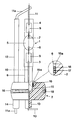
- the figure shows a 35 watt metal halide discharge lamp with a discharge vessel 1 made of quartz glass, a base-side 3 and a base-side pinch end 4 and a tubular extension 6, which is molded directly onto the base-side pinch 3.
- a discharge vessel 1 made of quartz glass
- the holder part 2 serves to hold the discharge vessel 1 and is welded by means of the steel ring 18 to the base sleeve, not shown.
- the connection of holder part 2 and base sleeve, which together form the lamp base, is disclosed in EP-PA 0 231 936.
- the discharge space 5 contains mercury, a noble gas or a noble gas mixture and metal halide additives as a filling.
- two mutually opposite electrodes 7 and 8 are arranged within the discharge space 5, each of which is supplied with electrical energy via a molybdenum foil 9 and current leads 10, 11 and 11a.
- the part of the power supply line 11a which runs parallel to the discharge vessel 1 has a ceramic sleeve 12 which prevents photoionization by UV rays and prevents it of electrical breakdowns between the two power supplies 10 and 11 is used.
- the discharge vessel 1 is inserted with its tubular extension 6 in the receptacle 15, which is designed here as an axial bore in the holder part 2 and whose diameter of approximately 5 mm corresponds to the outer diameter of the extension 6.
- the receptacle 15 has an expansion 15a at its end facing the surface of the holder part 2, in which a coil spring 16 made of spring steel with three turns is arranged, which is used for high-frequency-induced heating of the plastic material by the holder part 2 in the immediate vicinity of the expansion 15a.
- the diameter of the expansion 15a is approximately 6 mm and is adapted to the outer diameter of the coil spring 16.
- the holder part 2 consists of a high-temperature-resistant thermoplastic material, for example polyether ketone or polyphenylene sulfide, the melting temperature of which is between approximately 300-500 ° C. It has bushings for the power supply lines 10 and 11a, which open into shafts 13 and 14 molded onto the holder part 2.
- the base-side power supply line 10 is bent at right angles to the shaft 14 of the power supply line 11a immediately after it emerges from the shaft 13, so that the distance between the two power supply lines 10 and 11a increases.
- the discharge vessel 1 of this lamp with its tubular Extension 6 can be made by any known method.
- the receptacle 15 and its widening 15a are designed as axial bores in the holder part 2, the diameters of the bores being adapted to the outside diameters of the tubular extension 6 or the helical spring 16.
- the depth of the receptacle 15 extends approximately to half the height of the barrel-shaped holder part 2.
- a helical spring 16 made of spring steel is pushed over approximately the last third of the tubular extension 6 of the discharge vessel 1, said spring 16 being tight against the outer wall of the extension 6.
- the tubular extension 6 is inserted together with the coil spring 16 to the desired depth, preferably up to the stop, into the receptacle 15 and the coil spring 16 is countersunk in the widening 15a.
- a conductor loop is placed on the top of the holder part 2 around the tubular extension 6, that is to say in the immediate vicinity of the helical spring 16, which is arranged as a primary winding in an electrical circuit with a high-frequency generator.
- a high-frequency pulse of short duration is sent from the high-frequency generator through the conductor loop, which induces a high current pulse in the coil spring 16, so that the thermoplastic material of the holder part 2 melts in the immediate vicinity of the coil spring 16.
- the melt 17 swells between the turns of the helical spring 16 to the quartz glass wall of the tubular extension 6, so that after the melt has cooled, the discharge vessel 1 and the holder part 2 have a positive contact, which is characterized by very good adhesive adhesion at the interface from the quartz glass of the extension 6 to the thermoplastic material of the holder part 2.
- the heating temperature of the thermoplastic material is determined by the duration of the high-frequency pulse and here is approximately 800 ° C., which is considerably lower than the melting temperature of the quartz glass wall of the tubular extension 6.
- the operating temperature of the tubular extension 6 is sufficiently high at approximately 160 ° C. below the melting temperature of the thermoplastic material of the holder part 2, so that the connection between the discharge vessel 1 and the holder part 2 is not destroyed during the operation of the lamp.
- the manufacturing process described here by way of example is not limited to the 35 watt metal halide discharge lamp set out in the exemplary embodiment, but can also be used for other lamp types, in particular also for halogen incandescent lamps which have a quartz or a hard glass bulb and only have a one-sided vessel closure, e.g. a bruise are provided.
Landscapes
- Common Detailed Techniques For Electron Tubes Or Discharge Tubes (AREA)
- Non-Portable Lighting Devices Or Systems Thereof (AREA)
- Vessels And Coating Films For Discharge Lamps (AREA)
Abstract
Die Erfindung betrifft eine einseitig gesockelte elektrische Lampe, vorzugsweise eine Hochdruck-Entladungslampe zur Verwendung in einem Kfz-Scheinwerfer, sowie ein Verfahren zur Herstellung einer solchen Lampe. Um einen formschlüssigen, erschütterungssicheren Festsitz des Lampenkolbens (1) im Halterteil (2) des Sockels zu gewährleisten, ist im Halterteil (2) im Bereich der rohrförmigen Verlängerung (6) des Lampenkolbens (1) ein zur hochfrequenzinduzierten Erwärmung taugliches Mittel (16) angeordnet. In diesem wird mit Hilfe einer externen Vorrichtung ein HF-Impuls induziert, so daß die Kunststoffmasse (17) des Halterteils (2) im Bereich der Verlängerung (6) des Lampenkolbens (1) schmilzt. Nach dem Erkalten der Kunststoffschmelze (17) besteht zwischen der Wand des Lampenkolbens (1) und dem Material des Halterteils (2) eine gute adhäsive Haftverbindung.
Description
Die Erfindung betrifft eine einseitig gesockelte elektrische Lampe gemäß dem Oberbegriff des Patentanspruchs 1.The invention relates to an electric lamp with a base on one side according to the preamble of patent claim 1.
Aus der DD-PS 245 080 ist eine einseitig gesockelte Gasentladungslampe für Kfz-Scheinwerfer bekannt, die ein als Soffitte ausgebildetes Entladungsgefäß aus Hart- oder Quarzglas mit partiellen Quetschungen bzw. Einschmelzungen besitzt, wobei das sockelseitige Gefäßende eine rohrförmige Verlängerung aufweist, welche im Lampensockel fixiert ist. An die Stromzuführung der sockelfernen Elektrode schließt sich eine elektrische Zuleitung an, die teilweise parallel zum Entladungsgefäß verläuft und zum Sockel zurückgeführt ist. Das Entladungsgefäß wird mittels seiner rohrförmigen Verlängerung in einer Aufnahmevorrichtung im Isolierteil des Sockels zentriert und mit Hilfe der Stromzuführungen, die mit dem Mittelkontakt und mit der elektrischen Zuleitung verbunden sind, befestigt.From DD-PS 245 080 a gas discharge lamp for motor vehicle headlights with a base on one side is known, which has a discharge vessel made of hard or quartz glass with partial crushing or melting, the end of the vessel end having a tubular extension which is fixed in the lamp base is. An electrical supply line is connected to the power supply of the electrode remote from the base, which leads partially parallel to the discharge vessel and is returned to the base. The discharge vessel is centered by means of its tubular extension in a receiving device in the insulating part of the base and fastened with the aid of the current leads which are connected to the center contact and to the electrical supply line.
Ein Nachteil dieser Lampe, die vorzugsweise in Kfz-Scheinwerfern eingesetzt wird, ist darin zu sehen, daß die Stromzuführungen hier einer hohen mechanischen Belastung durch Erschütterungen etc. ausgesetzt sind, weil sie bei dieser Konstruktion auch zur Halterung und Befestigung des Entladungsgefäßes dienen. Diese hohe mechanische Beanspruchung der Stromzuführungen kann möglicherweise zu Kontaktunterbrechungen und damit zu einem verfrühten Ausfall der Lampen führen.A disadvantage of this lamp, which is preferably used in motor vehicle headlights, can be seen in the fact that the power supplies here are exposed to a high mechanical load due to vibrations, etc., because in this construction they also serve to hold and fasten the discharge vessel. This high mechanical stress on the power supply can possibly lead to interruptions in the contact and thus lead to premature lamp failure.
Der Erfindung liegt die Aufgabe zugrunde, eine einseitig gesockelte elektrische Lampe bereitzustellen, die einen formschlüssigen, leicht herstellbaren Festsitz des Lampenkolbens im Halterteil des Sockels aufweist. Außerdem soll bei der Lampenmontage die Lage des Lampenkolbens im Halterteil leicht justierbar sein.The object of the invention is to provide an electric lamp with a base on one side, which has a form-fitting, easy-to-produce tight fit of the lamp bulb in the holder part of the base. In addition, the position of the lamp bulb in the holder part should be easily adjustable during lamp assembly.
Diese Aufgabe wird erfindungsgemäß durch die kennzeichnenden Merkmale des Anspruchs 1 gelöst. Besonders vorteilhafte Ausführungen finden sich in den abhängigen Ansprüchen.This object is achieved by the characterizing features of claim 1. Particularly advantageous designs can be found in the dependent claims.
Mit der Erfindung werden folgende Vorteile erzielt:
Die Position des Lampenkolbens, der mit seiner rohrförmigen Verlängerung in der Aufnahmevorrichtung steckt, kann vor der Fixierung in axialer Richtung leicht justiert werden. Das zur hochfrequenzinduzierten Erwärmung taugliche Mittel ermöglicht sodann eine Anschmelzung des Halterteilmaterials in unmittelbarer Nähe der rohrförmigen Verlängerung des Lampenkolbens, so daß nach dem Erkalten der Schmelze der Lampenkolben in seiner Lage fixiert ist und die rohrförmige Verlängerung mit dem Halterteil einen formschlüssigen Kontakt bildet, der sich durch eine sehr gute adhäsive Haftung auszeichnet. Diese Art der Befestigung des Lampenkolbens im Halterteil ist für eine vollmechanisierte und kostengünstige Fertigung geeignet. Lampen dieser Konstruktion weisen einen stabilen, formschlüssigen und erschütterungssicheren Sitz im Sockel auf. Außerdem wird durch den Verzicht von metallischen Halteelementen die Hochspannungsfestigkeit des Lampensockels gegenüber Hochspannungsimpulsen, wie sie zum Heißwiederzünden einer Entladungslampe nötig sind, verbessert.The following advantages are achieved with the invention:
The position of the lamp bulb, which is in the receiving device with its tubular extension, can be easily adjusted in the axial direction before being fixed. The medium suitable for high-frequency-induced heating then enables the holder part material to melt in the immediate vicinity of the tubular extension of the lamp bulb, so that after the melt has cooled, the lamp bulb is fixed in its position and the tubular extension forms a positive contact with the holder part, which is formed by a very good adhesive adhesion. This type of attachment of the lamp bulb in the holder part is suitable for fully mechanized and inexpensive production. Lamps of this construction have a stable, form-fitting and vibration-proof seat in the base. In addition, the elimination of metallic holding elements improves the high-voltage strength of the lamp base against high-voltage pulses, as are necessary for the hot re-ignition of a discharge lamp.
Die Erfindung wird nun anhand eines besonders bevorzugten Ausführungsbeispiels beschrieben.The invention will now be described on the basis of a particularly preferred exemplary embodiment.
In der Figur ist eine 35 Watt-Metallhalogenid-Entladungslampe mit einem Entladungsgefäß 1 aus Quarzglas, einem sockelseitigen 3 und einem sockelfernen Quetschende 4 sowie einer rohrförmigen Verlängerung 6, die unmittelbar an die sockelseitige Quetschung 3 angeformt ist, dargestellt. Solche Lampen werden in Kfz-Scheinwerfern eingesetzt. Das Halterteil 2 dient zur Halterung des Entladungsgefäßes 1 und ist mitels des Stahlringes 18 mit der nicht gezeigten Sockelhülse verschweißt. Die Verbindung von Halterteil 2 und Sockelhülse, die zusammen den Lampensockel bilden, ist in der EP-PA 0 231 936 offenbart. Der Entladungsraum 5 enthält als Füllung Quecksilber, ein Edelgas oder ein Edelgasgemisch und Metallhalogenidzusätze. Außerdem sind innerhalb des Entladungsraumes 5 zwei einander gegenüberliegende Elektroden 7 und 8 angeordnet, die jeweils über eine Molybdänfolie 9 und Stromzuführungen 10, 11 und 11a mit elektrischer Energie versorgt werden. Der parallel zum Entladungsgefäß 1 verlaufende Teil der Stromzuführung 11a besitzt eine Keramikhülle 12, die zur Vermeidung von Photoionisation durch UV-Strahlen und zur Vermeidung von elektrischen Durchschlägen zwischen den beiden Stromzuführungen 10 und 11 dient. Das Entladunsgefäß 1 steckt mit seiner rohrförmigen Verlängerung 6 in der Aufnahme 15, die hier als axiale Bohrung im Halterteil 2 ausgeführt ist und deren Durchmesser von ca. 5 mm dem Außendurchmesser der Verlängerung 6 entspricht. Die Aufnahme 15 weist an ihrem der Oberfläche des Halterteils 2 zugewandten Ende eine Aufweitung 15a auf, in der eine Schraubenfeder 16 aus Federstahl mit drei Windungen angeordnet ist, die zur hochfrequenzinduzierten Erwärmung des Kunststoffmaterials vom Halterteil 2 in unmittelbarer Umgebung der Aufweitung 15a eingesetzt wird. Der Durchmesser der Aufweitung 15a beträgt ca. 6 mm und ist dem Außendurchmesser der Schraubenfeder 16 angepaßt. Das Halterteil 2 besteht aus einem hochtemperaturfesten thermoplastischen Material, z.B. Polyätherketon oder Polyphenylensulfid, dessen Schmelztemperatur zwischen ca. 300 - 500°C liegt. Es besitzt Durchführungen für die Stromzuführungen 10 und 11a, die in an das Halterteil 2 angeformte Schäfte 13 und 14 münden. Die sockelseitige Stromzuführung 10 wird unmittelbar nach ihrem Austritt aus dem Schaft 13 rechtwinklig vom Schaft 14 der Stromzuführung 11a abgebogen, so daß sich der Abstand zwischen den beiden Stromzuführungen 10 und 11a vergrößert.The figure shows a 35 watt metal halide discharge lamp with a discharge vessel 1 made of quartz glass, a base-
Das Herstellungsverfahren einer erfindungsgemäßen, einseitig gesockelten elektrischen Lampe wird anhand der oben beschriebenen 35 Watt-Metallhalogenid-Entladungslampe exemplarisch erläutert.The manufacturing process of an electric lamp according to the invention, which is capped on one side, is explained by way of example using the 35 watt metal halide discharge lamp described above.
Das Entladungsgefäß 1 dieser Lampe mit seiner rohrförmigen Verlängerung 6 kann nach irgendeinem bekannten Verfahren gefertigt werden. Die Aufnahme 15 und ihre Aufweitung 15a werden als axiale Bohrungen im Halterteil 2 ausgeführt, wobei die Durchmesser der Bohrungen den Außendurchmessern der rohrförmigen Verlängerung 6 bzw. der Schraubenfeder 16 angepaßt sind. Die Tiefe der Aufnahme 15 erstreckt sich ungefähr bis zur halben Höhe des faßförmigen Halterteils 2. Über ca. das letzte Drittel der rohrförmigen Verlängerung 6 des Entladungsgefäßes 1 wird eine Schraubenfeder 16 aus Federstahl geschoben, die eng an der Außenwand der Verlängerung 6 anliegt. Die rohrförmige Verlängerung 6 wird zusammen mit der Schraubenfeder 16 bis zur gewünschten Tiefe, vorzugsweise bis zum Anschlag, in die Aufnahme 15 eingeführt und die Schraubenfeder 16 dabei in der Aufweitung 15a versenkt. Zur Fixierung des Entladungsgefäßes 1 im Halterteil 2 wird auf die Oberseite des Halterteils 2 um die rohrförmige Verlängerung 6 herum, also in unmittelbarer Nähe der Schraubenfeder 16, eine Leiterschlaufe gelegt, die als Primärwicklung in einem elektrischen Stromkreis mit einem Hochfrequenz-Generator angeordnet ist. Vom Hochfrequenz-Generator wird ein Hochfrequenzimpuls von kurzer Dauer durch die Leiterschlaufe geschickt, der in der Schraubenfeder 16 einen hohen Stromimpuls induziert, so daß das thermoplastische Material des Halterteils 2 in der unmittelbaren Umgebung der Schraubenfeder 16 schmilzt. Die Schmelze 17 quillt zwischen die Windungen der Schraubenfeder 16 hindurch zur Quarzglaswand der rohrförmigen Verlängerung 6, so daß nach dem Erkalten der Schmelze das Entladungsgefäß 1 und das Halterteil 2 einen formschlüssigen Kontakt besitzen, der sich durch eine sehr gute adhäsive Haftung an der Grenzfläche vom Quarzglas der Verlängerung 6 zum thermoplastischen Material des Halterteils 2 auszeichnet. Die Aufheiztemperatur des thermoplastischen Materials wird durch die Dauer des Hochfrequenzimpulses bestimmt und beträgt hier ca. 800°C, ist also erheblich niedriger als die Schmelztemperatur der Quarzglaswand der rohrförmigen Verlängerung 6. Die Betriebstemperatur der rohrförmigen Verlängerung 6 liegt mit ca. 160°C genügend weit unterhalb der Schmelztemperatur des thermoplastischen Materials des Halterteils 2, so daß die Verbindung von Entladungsgefäß 1 und Halterteil 2 während des Betriebes der Lampe nicht zerstört wird.The discharge vessel 1 of this lamp with its
Das hier exemplarisch beschriebene Herstellungsverfahren ist nicht auf die im Ausführungsbeispiel dargelegte 35 Watt-Metallhalogenid-Entladungslampe beschränkt, sondern kann auch auf andere Lampentypen, insbesondere auch auf Halogen-Glühlampen, die einen Quarz- oder einen Hartglaskolben besitzen und nur mit einem einseitigen Gefäßabschluß, z.B. einer Quetschung, versehen sind, angewendet werden.The manufacturing process described here by way of example is not limited to the 35 watt metal halide discharge lamp set out in the exemplary embodiment, but can also be used for other lamp types, in particular also for halogen incandescent lamps which have a quartz or a hard glass bulb and only have a one-sided vessel closure, e.g. a bruise are provided.
Claims (18)
Applications Claiming Priority (2)
| Application Number | Priority Date | Filing Date | Title |
|---|---|---|---|
| DE4014745A DE4014745A1 (en) | 1990-05-08 | 1990-05-08 | ELECTRIC LAMP BASED ON ONE SIDE |
| DE4014745 | 1990-05-08 |
Publications (3)
| Publication Number | Publication Date |
|---|---|
| EP0455884A2 true EP0455884A2 (en) | 1991-11-13 |
| EP0455884A3 EP0455884A3 (en) | 1992-04-01 |
| EP0455884B1 EP0455884B1 (en) | 1994-03-23 |
Family
ID=6405956
Family Applications (1)
| Application Number | Title | Priority Date | Filing Date |
|---|---|---|---|
| EP90124910A Expired - Lifetime EP0455884B1 (en) | 1990-05-08 | 1990-12-20 | Single-cap lamp |
Country Status (4)
| Country | Link |
|---|---|
| US (1) | US5270610A (en) |
| EP (1) | EP0455884B1 (en) |
| JP (1) | JP2875046B2 (en) |
| DE (2) | DE4014745A1 (en) |
Cited By (3)
| Publication number | Priority date | Publication date | Assignee | Title |
|---|---|---|---|---|
| EP0696046A2 (en) | 1994-08-04 | 1996-02-07 | Patent-Treuhand-Gesellschaft für elektrische Glühlampen mbH | Single-ended high pressure discharge lamp |
| KR100708497B1 (en) * | 1999-06-23 | 2007-04-16 | 파텐트-트로이한트-게젤샤프트 퓌어 엘렉트리쉐 글뤼람펜 엠베하 | How to mount the base of the electric lamp |
| EP1439569A3 (en) * | 2003-01-03 | 2007-08-29 | General Electric Company | Discharge lamp with a base and method and fixture for manufacturing the same |
Families Citing this family (10)
| Publication number | Priority date | Publication date | Assignee | Title |
|---|---|---|---|---|
| JPH0520256U (en) * | 1991-06-04 | 1993-03-12 | エヌ・ベー・フイリツプス・フルーイランペンフアブリケン | High pressure gas discharge lamp |
| NL9200421A (en) * | 1992-03-06 | 1993-10-01 | Philips Nv | SOCKET ELECTRIC LAMP AND CONNECTOR THEREFOR. |
| JP2769274B2 (en) * | 1993-02-16 | 1998-06-25 | 株式会社小糸製作所 | Insulating base for discharge lamp device |
| DE9313823U1 (en) * | 1993-09-13 | 1993-11-11 | Patent-Treuhand-Gesellschaft für elektrische Glühlampen mbH, 81543 München | Electric lamp |
| CA2147517C (en) * | 1994-04-25 | 2006-03-21 | Walter Newman | Lampholder with mogul base |
| DE19951873A1 (en) * | 1999-10-28 | 2001-05-03 | Patent Treuhand Ges Fuer Elektrische Gluehlampen Mbh | Discharge lamp |
| DE10015558C2 (en) * | 2000-03-30 | 2002-03-14 | Heraeus Noblelight Gmbh | Optical spotlight |
| DE10160383A1 (en) * | 2001-12-10 | 2003-06-18 | Patent Treuhand Ges Fuer Elektrische Gluehlampen Mbh | Reflector lamp has lamp vessel with at least one sealed end with reduced dimension relative to lamp vessel, at least in direction perpendicular to longitudinal axis |
| DE102004058881A1 (en) * | 2004-12-06 | 2006-06-08 | Patent-Treuhand-Gesellschaft für elektrische Glühlampen mbH | High pressure discharge lamp and lighting device with high pressure discharge lamp |
| WO2011048517A1 (en) * | 2009-10-19 | 2011-04-28 | Koninklijke Philips Electronics N.V. | High intensity discharge lamp |
Family Cites Families (9)
| Publication number | Priority date | Publication date | Assignee | Title |
|---|---|---|---|---|
| US1873776A (en) * | 1926-03-31 | 1932-08-23 | Gen Electric | Method of basing vacuum tubes and similar articles |
| GB909991A (en) * | 1958-02-19 | 1962-11-07 | Ass Elect Ind | Improvements relating to the cementing of the bases of thermionic valves and the like to their envelopes |
| DE2634980C3 (en) * | 1976-08-04 | 1979-01-25 | Original Hanau Quarzlampen Gmbh, 6450 Hanau | Radiators that can be fastened to brackets and have angular pinches surrounded by base sleeves, as well as method and device for connecting the pinches of the radiator to the base sleeves |
| JPS57124830A (en) * | 1981-01-27 | 1982-08-03 | Sony Corp | Sealing method for cathode-ray tube |
| DE8522797U1 (en) * | 1985-08-07 | 1985-10-31 | Patent-Treuhand-Gesellschaft für elektrische Glühlampen mbH, 8000 München | Electric lamp with a putty-free base |
| DD245080A1 (en) * | 1985-12-23 | 1987-04-22 | Narva Rosa Luxemburg K | GAS DISCHARGE LAMP FOR MOTOR VEHICLE HEADLIGHTS |
| DE3603753A1 (en) * | 1986-02-06 | 1987-08-20 | Patent Treuhand Ges Fuer Elektrische Gluehlampen Mbh | ELECTRIC LAMP |
| DE3776245D1 (en) * | 1986-09-22 | 1992-03-05 | Philips Nv | ELECTRIC LAMP. |
| US4982131A (en) * | 1989-08-01 | 1991-01-01 | Gte Products Corporation | Reflector lamp assembly utilizing lamp capsule that snaps directly into reflector |
-
1990
- 1990-05-08 DE DE4014745A patent/DE4014745A1/en not_active Withdrawn
- 1990-12-20 DE DE90124910T patent/DE59005124D1/en not_active Expired - Lifetime
- 1990-12-20 EP EP90124910A patent/EP0455884B1/en not_active Expired - Lifetime
-
1991
- 1991-05-01 US US07/694,465 patent/US5270610A/en not_active Expired - Lifetime
- 1991-05-08 JP JP10255591A patent/JP2875046B2/en not_active Expired - Lifetime
Cited By (3)
| Publication number | Priority date | Publication date | Assignee | Title |
|---|---|---|---|---|
| EP0696046A2 (en) | 1994-08-04 | 1996-02-07 | Patent-Treuhand-Gesellschaft für elektrische Glühlampen mbH | Single-ended high pressure discharge lamp |
| KR100708497B1 (en) * | 1999-06-23 | 2007-04-16 | 파텐트-트로이한트-게젤샤프트 퓌어 엘렉트리쉐 글뤼람펜 엠베하 | How to mount the base of the electric lamp |
| EP1439569A3 (en) * | 2003-01-03 | 2007-08-29 | General Electric Company | Discharge lamp with a base and method and fixture for manufacturing the same |
Also Published As
| Publication number | Publication date |
|---|---|
| DE4014745A1 (en) | 1991-11-14 |
| EP0455884A3 (en) | 1992-04-01 |
| JPH04229545A (en) | 1992-08-19 |
| JP2875046B2 (en) | 1999-03-24 |
| DE59005124D1 (en) | 1994-04-28 |
| EP0455884B1 (en) | 1994-03-23 |
| US5270610A (en) | 1993-12-14 |
Similar Documents
| Publication | Publication Date | Title |
|---|---|---|
| EP0786791B1 (en) | Electric lamp | |
| DE69804192T2 (en) | HIGH PRESSURE DISCHARGE LAMP WITH UV AMPLIFIER | |
| EP1635619B1 (en) | High-pressure discharge lamp with transformer | |
| EP0455884B1 (en) | Single-cap lamp | |
| EP0886882B1 (en) | Gas discharge lamp, in particular for a motor-vehicle headlight | |
| DE19855412A1 (en) | Electric lamp | |
| DE3439171A1 (en) | SINGLE-SIDED BASED MERCURY STEAM LOW-PRESSURE DISCHARGE LAMP | |
| EP1088335B1 (en) | Discharge lamp with base | |
| DE19629714C1 (en) | Process for the production of connection contacts for spotlights with quartz glass pistons | |
| DE1234313B (en) | Method for producing a welded connection between the power supply wires and the base contacts of an electric lamp | |
| EP0134390B1 (en) | Lead-through insulators, especially for refrigerating machines | |
| EP1147534B1 (en) | Discharge lamp | |
| EP0168031B1 (en) | Electrical lamp | |
| EP0854497A2 (en) | Compact low pressure discharge lamp | |
| DE69323595T2 (en) | Inner part of a lamp housing | |
| EP0588201B1 (en) | High pressure discharge lamp and methof of manufacturing a high pressure discharge lamp | |
| EP0930635A2 (en) | Single-ended high pressure discharge lamp | |
| DE102004025268A1 (en) | vehicle lamp | |
| DE69408787T2 (en) | Discharge lamp provided with a bimetallic switch and a bimetallic switch suitable for a lamp | |
| EP0923105B1 (en) | Compact low pressure discharge lamp | |
| DE3334166A1 (en) | LAMP CONSTRUCTION | |
| DE3147705A1 (en) | START-UP AID FOR NON-LINEAR DISCHARGE LAMPS AND METHOD FOR THE PRODUCTION THEREOF | |
| EP2529389A1 (en) | High-pressure discharge lamp having a capacitive ignition aid | |
| DE10312720A1 (en) | Dielectric barrier discharge lamp with crimp seal | |
| EP1624473A2 (en) | Dielectric barrier discharge lamp with solder-free contacts |
Legal Events
| Date | Code | Title | Description |
|---|---|---|---|
| PUAI | Public reference made under article 153(3) epc to a published international application that has entered the european phase |
Free format text: ORIGINAL CODE: 0009012 |
|
| 17P | Request for examination filed |
Effective date: 19901220 |
|
| AK | Designated contracting states |
Kind code of ref document: A2 Designated state(s): DE FR GB IT SE |
|
| PUAL | Search report despatched |
Free format text: ORIGINAL CODE: 0009013 |
|
| AK | Designated contracting states |
Kind code of ref document: A3 Designated state(s): DE FR GB IT SE |
|
| 17Q | First examination report despatched |
Effective date: 19930625 |
|
| GRAA | (expected) grant |
Free format text: ORIGINAL CODE: 0009210 |
|
| AK | Designated contracting states |
Kind code of ref document: B1 Designated state(s): DE FR GB IT SE |
|
| REF | Corresponds to: |
Ref document number: 59005124 Country of ref document: DE Date of ref document: 19940428 |
|
| ITF | It: translation for a ep patent filed | ||
| GBT | Gb: translation of ep patent filed (gb section 77(6)(a)/1977) |
Effective date: 19940531 |
|
| ET | Fr: translation filed | ||
| PLBE | No opposition filed within time limit |
Free format text: ORIGINAL CODE: 0009261 |
|
| STAA | Information on the status of an ep patent application or granted ep patent |
Free format text: STATUS: NO OPPOSITION FILED WITHIN TIME LIMIT |
|
| EAL | Se: european patent in force in sweden |
Ref document number: 90124910.2 |
|
| 26N | No opposition filed | ||
| REG | Reference to a national code |
Ref country code: GB Ref legal event code: IF02 |
|
| PGFP | Annual fee paid to national office [announced via postgrant information from national office to epo] |
Ref country code: GB Payment date: 20051208 Year of fee payment: 16 Ref country code: SE Payment date: 20051208 Year of fee payment: 16 |
|
| PGFP | Annual fee paid to national office [announced via postgrant information from national office to epo] |
Ref country code: FR Payment date: 20051216 Year of fee payment: 16 |
|
| PG25 | Lapsed in a contracting state [announced via postgrant information from national office to epo] |
Ref country code: SE Free format text: LAPSE BECAUSE OF NON-PAYMENT OF DUE FEES Effective date: 20061221 |
|
| PGFP | Annual fee paid to national office [announced via postgrant information from national office to epo] |
Ref country code: IT Payment date: 20061231 Year of fee payment: 17 |
|
| EUG | Se: european patent has lapsed | ||
| GBPC | Gb: european patent ceased through non-payment of renewal fee |
Effective date: 20061220 |
|
| REG | Reference to a national code |
Ref country code: FR Ref legal event code: ST Effective date: 20070831 |
|
| PG25 | Lapsed in a contracting state [announced via postgrant information from national office to epo] |
Ref country code: GB Free format text: LAPSE BECAUSE OF NON-PAYMENT OF DUE FEES Effective date: 20061220 |
|
| PG25 | Lapsed in a contracting state [announced via postgrant information from national office to epo] |
Ref country code: FR Free format text: LAPSE BECAUSE OF NON-PAYMENT OF DUE FEES Effective date: 20070102 |
|
| PG25 | Lapsed in a contracting state [announced via postgrant information from national office to epo] |
Ref country code: IT Free format text: LAPSE BECAUSE OF NON-PAYMENT OF DUE FEES Effective date: 20071220 |
|
| PGFP | Annual fee paid to national office [announced via postgrant information from national office to epo] |
Ref country code: DE Payment date: 20100219 Year of fee payment: 20 |
|
| PG25 | Lapsed in a contracting state [announced via postgrant information from national office to epo] |
Ref country code: DE Free format text: LAPSE BECAUSE OF EXPIRATION OF PROTECTION Effective date: 20101220 |