EP0455884A2 - Lampe fixée d'un côté - Google Patents
Lampe fixée d'un côté Download PDFInfo
- Publication number
- EP0455884A2 EP0455884A2 EP90124910A EP90124910A EP0455884A2 EP 0455884 A2 EP0455884 A2 EP 0455884A2 EP 90124910 A EP90124910 A EP 90124910A EP 90124910 A EP90124910 A EP 90124910A EP 0455884 A2 EP0455884 A2 EP 0455884A2
- Authority
- EP
- European Patent Office
- Prior art keywords
- lamp
- base
- tubular extension
- holder part
- side according
- Prior art date
- Legal status (The legal status is an assumption and is not a legal conclusion. Google has not performed a legal analysis and makes no representation as to the accuracy of the status listed.)
- Granted
Links
Images
Classifications
-
- H—ELECTRICITY
- H01—ELECTRIC ELEMENTS
- H01J—ELECTRIC DISCHARGE TUBES OR DISCHARGE LAMPS
- H01J5/00—Details relating to vessels or to leading-in conductors common to two or more basic types of discharge tubes or lamps
- H01J5/48—Means forming part of the tube or lamp for the purpose of supporting it
Definitions
- the invention relates to an electric lamp with a base on one side according to the preamble of patent claim 1.
- a gas discharge lamp for motor vehicle headlights with a base on one side which has a discharge vessel made of hard or quartz glass with partial crushing or melting, the end of the vessel end having a tubular extension which is fixed in the lamp base is.
- An electrical supply line is connected to the power supply of the electrode remote from the base, which leads partially parallel to the discharge vessel and is returned to the base.
- the discharge vessel is centered by means of its tubular extension in a receiving device in the insulating part of the base and fastened with the aid of the current leads which are connected to the center contact and to the electrical supply line.
- the object of the invention is to provide an electric lamp with a base on one side, which has a form-fitting, easy-to-produce tight fit of the lamp bulb in the holder part of the base.
- the position of the lamp bulb in the holder part should be easily adjustable during lamp assembly.
- the position of the lamp bulb, which is in the receiving device with its tubular extension can be easily adjusted in the axial direction before being fixed.
- the medium suitable for high-frequency-induced heating then enables the holder part material to melt in the immediate vicinity of the tubular extension of the lamp bulb, so that after the melt has cooled, the lamp bulb is fixed in its position and the tubular extension forms a positive contact with the holder part, which is formed by a very good adhesive adhesion.
- This type of attachment of the lamp bulb in the holder part is suitable for fully mechanized and inexpensive production.
- Lamps of this construction have a stable, form-fitting and vibration-proof seat in the base.
- the elimination of metallic holding elements improves the high-voltage strength of the lamp base against high-voltage pulses, as are necessary for the hot re-ignition of a discharge lamp.
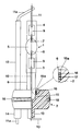
- the figure shows a 35 watt metal halide discharge lamp with a discharge vessel 1 made of quartz glass, a base-side 3 and a base-side pinch end 4 and a tubular extension 6, which is molded directly onto the base-side pinch 3.
- a discharge vessel 1 made of quartz glass
- the holder part 2 serves to hold the discharge vessel 1 and is welded by means of the steel ring 18 to the base sleeve, not shown.
- the connection of holder part 2 and base sleeve, which together form the lamp base, is disclosed in EP-PA 0 231 936.
- the discharge space 5 contains mercury, a noble gas or a noble gas mixture and metal halide additives as a filling.
- two mutually opposite electrodes 7 and 8 are arranged within the discharge space 5, each of which is supplied with electrical energy via a molybdenum foil 9 and current leads 10, 11 and 11a.
- the part of the power supply line 11a which runs parallel to the discharge vessel 1 has a ceramic sleeve 12 which prevents photoionization by UV rays and prevents it of electrical breakdowns between the two power supplies 10 and 11 is used.
- the discharge vessel 1 is inserted with its tubular extension 6 in the receptacle 15, which is designed here as an axial bore in the holder part 2 and whose diameter of approximately 5 mm corresponds to the outer diameter of the extension 6.
- the receptacle 15 has an expansion 15a at its end facing the surface of the holder part 2, in which a coil spring 16 made of spring steel with three turns is arranged, which is used for high-frequency-induced heating of the plastic material by the holder part 2 in the immediate vicinity of the expansion 15a.
- the diameter of the expansion 15a is approximately 6 mm and is adapted to the outer diameter of the coil spring 16.
- the holder part 2 consists of a high-temperature-resistant thermoplastic material, for example polyether ketone or polyphenylene sulfide, the melting temperature of which is between approximately 300-500 ° C. It has bushings for the power supply lines 10 and 11a, which open into shafts 13 and 14 molded onto the holder part 2.
- the base-side power supply line 10 is bent at right angles to the shaft 14 of the power supply line 11a immediately after it emerges from the shaft 13, so that the distance between the two power supply lines 10 and 11a increases.
- the discharge vessel 1 of this lamp with its tubular Extension 6 can be made by any known method.
- the receptacle 15 and its widening 15a are designed as axial bores in the holder part 2, the diameters of the bores being adapted to the outside diameters of the tubular extension 6 or the helical spring 16.
- the depth of the receptacle 15 extends approximately to half the height of the barrel-shaped holder part 2.
- a helical spring 16 made of spring steel is pushed over approximately the last third of the tubular extension 6 of the discharge vessel 1, said spring 16 being tight against the outer wall of the extension 6.
- the tubular extension 6 is inserted together with the coil spring 16 to the desired depth, preferably up to the stop, into the receptacle 15 and the coil spring 16 is countersunk in the widening 15a.
- a conductor loop is placed on the top of the holder part 2 around the tubular extension 6, that is to say in the immediate vicinity of the helical spring 16, which is arranged as a primary winding in an electrical circuit with a high-frequency generator.
- a high-frequency pulse of short duration is sent from the high-frequency generator through the conductor loop, which induces a high current pulse in the coil spring 16, so that the thermoplastic material of the holder part 2 melts in the immediate vicinity of the coil spring 16.
- the melt 17 swells between the turns of the helical spring 16 to the quartz glass wall of the tubular extension 6, so that after the melt has cooled, the discharge vessel 1 and the holder part 2 have a positive contact, which is characterized by very good adhesive adhesion at the interface from the quartz glass of the extension 6 to the thermoplastic material of the holder part 2.
- the heating temperature of the thermoplastic material is determined by the duration of the high-frequency pulse and here is approximately 800 ° C., which is considerably lower than the melting temperature of the quartz glass wall of the tubular extension 6.
- the operating temperature of the tubular extension 6 is sufficiently high at approximately 160 ° C. below the melting temperature of the thermoplastic material of the holder part 2, so that the connection between the discharge vessel 1 and the holder part 2 is not destroyed during the operation of the lamp.
- the manufacturing process described here by way of example is not limited to the 35 watt metal halide discharge lamp set out in the exemplary embodiment, but can also be used for other lamp types, in particular also for halogen incandescent lamps which have a quartz or a hard glass bulb and only have a one-sided vessel closure, e.g. a bruise are provided.
Landscapes
- Common Detailed Techniques For Electron Tubes Or Discharge Tubes (AREA)
- Non-Portable Lighting Devices Or Systems Thereof (AREA)
- Vessels And Coating Films For Discharge Lamps (AREA)
Applications Claiming Priority (2)
| Application Number | Priority Date | Filing Date | Title |
|---|---|---|---|
| DE4014745 | 1990-05-08 | ||
| DE4014745A DE4014745A1 (de) | 1990-05-08 | 1990-05-08 | Einseitig gesockelte elektrische lampe |
Publications (3)
| Publication Number | Publication Date |
|---|---|
| EP0455884A2 true EP0455884A2 (fr) | 1991-11-13 |
| EP0455884A3 EP0455884A3 (en) | 1992-04-01 |
| EP0455884B1 EP0455884B1 (fr) | 1994-03-23 |
Family
ID=6405956
Family Applications (1)
| Application Number | Title | Priority Date | Filing Date |
|---|---|---|---|
| EP90124910A Expired - Lifetime EP0455884B1 (fr) | 1990-05-08 | 1990-12-20 | Lampe fixée d'un côté |
Country Status (4)
| Country | Link |
|---|---|
| US (1) | US5270610A (fr) |
| EP (1) | EP0455884B1 (fr) |
| JP (1) | JP2875046B2 (fr) |
| DE (2) | DE4014745A1 (fr) |
Cited By (3)
| Publication number | Priority date | Publication date | Assignee | Title |
|---|---|---|---|---|
| EP0696046A2 (fr) | 1994-08-04 | 1996-02-07 | Patent-Treuhand-Gesellschaft für elektrische Glühlampen mbH | Lampe à décharge à haute pression à culottage d'un seul cÔté |
| KR100708497B1 (ko) * | 1999-06-23 | 2007-04-16 | 파텐트-트로이한트-게젤샤프트 퓌어 엘렉트리쉐 글뤼람펜 엠베하 | 전기 램프의 기저부를 장착하는 방법 |
| EP1439569A3 (fr) * | 2003-01-03 | 2007-08-29 | General Electric Company | Lampe a décharge comprenant un socle et procédé et fixation pour sa fabrication |
Families Citing this family (10)
| Publication number | Priority date | Publication date | Assignee | Title |
|---|---|---|---|---|
| JPH0520256U (ja) * | 1991-06-04 | 1993-03-12 | エヌ・ベー・フイリツプス・フルーイランペンフアブリケン | 高圧ガス放電ランプ |
| NL9200421A (nl) * | 1992-03-06 | 1993-10-01 | Philips Nv | Gesokkelde elektrische lamp en connector daarvoor. |
| JP2769274B2 (ja) * | 1993-02-16 | 1998-06-25 | 株式会社小糸製作所 | 放電ランプ装置用絶縁性ベース |
| DE9313823U1 (de) * | 1993-09-13 | 1993-11-11 | Patent-Treuhand-Gesellschaft für elektrische Glühlampen mbH, 81543 München | Elektrische Lampe |
| CA2147517C (fr) * | 1994-04-25 | 2006-03-21 | Walter Newman | Douille de lampe a culot goliath |
| DE19951873A1 (de) * | 1999-10-28 | 2001-05-03 | Patent Treuhand Ges Fuer Elektrische Gluehlampen Mbh | Entladungslampe |
| DE10015558C2 (de) * | 2000-03-30 | 2002-03-14 | Heraeus Noblelight Gmbh | Optischer Strahler |
| DE10160383A1 (de) * | 2001-12-10 | 2003-06-18 | Patent Treuhand Ges Fuer Elektrische Gluehlampen Mbh | Reflektorlampe und Verfahren zur Herstellung einer Reflektorlampe |
| DE102004058881A1 (de) * | 2004-12-06 | 2006-06-08 | Patent-Treuhand-Gesellschaft für elektrische Glühlampen mbH | Hochdruckentladungslampe und Beleuchtungsvorrichtung mit Hochdruckentladungslampe |
| WO2011048517A1 (fr) * | 2009-10-19 | 2011-04-28 | Koninklijke Philips Electronics N.V. | Lampe à décharge à intensité élevée |
Family Cites Families (9)
| Publication number | Priority date | Publication date | Assignee | Title |
|---|---|---|---|---|
| US1873776A (en) * | 1926-03-31 | 1932-08-23 | Gen Electric | Method of basing vacuum tubes and similar articles |
| GB909991A (en) * | 1958-02-19 | 1962-11-07 | Ass Elect Ind | Improvements relating to the cementing of the bases of thermionic valves and the like to their envelopes |
| DE2634980C3 (de) * | 1976-08-04 | 1979-01-25 | Original Hanau Quarzlampen Gmbh, 6450 Hanau | An Halterungen befestigbarer Strahler mit von Sockelhülsen umgebenen kantigen Quetschungen sowie Verfahren und Vorrichtung zum Verbinden der Quetschungen des Strahlers mit den Sockelhülsen |
| JPS57124830A (en) * | 1981-01-27 | 1982-08-03 | Sony Corp | Sealing method for cathode-ray tube |
| DE8522797U1 (de) * | 1985-08-07 | 1985-10-31 | Patent-Treuhand-Gesellschaft für elektrische Glühlampen mbH, 8000 München | Kittlos gesockelte elektrische Lampe |
| DD245080A1 (de) * | 1985-12-23 | 1987-04-22 | Narva Rosa Luxemburg K | Gasentladungslampe fuer kraftfahrzeugscheinwerfer |
| DE3603753A1 (de) * | 1986-02-06 | 1987-08-20 | Patent Treuhand Ges Fuer Elektrische Gluehlampen Mbh | Elektrische lampe |
| DE3776245D1 (de) * | 1986-09-22 | 1992-03-05 | Philips Nv | Elektrische lampe. |
| US4982131A (en) * | 1989-08-01 | 1991-01-01 | Gte Products Corporation | Reflector lamp assembly utilizing lamp capsule that snaps directly into reflector |
-
1990
- 1990-05-08 DE DE4014745A patent/DE4014745A1/de not_active Withdrawn
- 1990-12-20 DE DE90124910T patent/DE59005124D1/de not_active Expired - Lifetime
- 1990-12-20 EP EP90124910A patent/EP0455884B1/fr not_active Expired - Lifetime
-
1991
- 1991-05-01 US US07/694,465 patent/US5270610A/en not_active Expired - Lifetime
- 1991-05-08 JP JP10255591A patent/JP2875046B2/ja not_active Expired - Lifetime
Cited By (3)
| Publication number | Priority date | Publication date | Assignee | Title |
|---|---|---|---|---|
| EP0696046A2 (fr) | 1994-08-04 | 1996-02-07 | Patent-Treuhand-Gesellschaft für elektrische Glühlampen mbH | Lampe à décharge à haute pression à culottage d'un seul cÔté |
| KR100708497B1 (ko) * | 1999-06-23 | 2007-04-16 | 파텐트-트로이한트-게젤샤프트 퓌어 엘렉트리쉐 글뤼람펜 엠베하 | 전기 램프의 기저부를 장착하는 방법 |
| EP1439569A3 (fr) * | 2003-01-03 | 2007-08-29 | General Electric Company | Lampe a décharge comprenant un socle et procédé et fixation pour sa fabrication |
Also Published As
| Publication number | Publication date |
|---|---|
| JPH04229545A (ja) | 1992-08-19 |
| DE4014745A1 (de) | 1991-11-14 |
| US5270610A (en) | 1993-12-14 |
| EP0455884A3 (en) | 1992-04-01 |
| DE59005124D1 (de) | 1994-04-28 |
| JP2875046B2 (ja) | 1999-03-24 |
| EP0455884B1 (fr) | 1994-03-23 |
Similar Documents
| Publication | Publication Date | Title |
|---|---|---|
| EP0786791B1 (fr) | Lampe électrique | |
| DE69804192T2 (de) | Hochdruckentladungslampe mit uv-verstärker | |
| EP1635619B1 (fr) | Lampe à décharge haute-pression avec transformateur | |
| EP0455884B1 (fr) | Lampe fixée d'un côté | |
| EP0886882B1 (fr) | Lampe luminescente a gaz, notamment pour phare de vehicule | |
| EP0580013A1 (fr) | Lampe à décharge haute pression à culotage d'un seul côté | |
| DE19855412A1 (de) | Elektrische Lampe | |
| DE3439171A1 (de) | Einseitig gesockelte quecksilberdampfniederdruckentladungslampe | |
| EP1088335B1 (fr) | Lampe a decharge comportant un culot | |
| DE19629714C1 (de) | Verfahren zur Herstellung von Anschlußkontakten für Strahler mit Quarzglas-Kolben | |
| DE1234313B (de) | Verfahren zur Herstellung einer Schweissverbindung zwischen den Strom-zuleitungsdraehten und den Sockelkontakten einer elektrischen Lampe | |
| EP1147534B1 (fr) | Lampe a decharge | |
| EP0854497A2 (fr) | Lampe compacte à décharge basse pression | |
| EP0588201B1 (fr) | Lampe à décharge haute pression et procédé pour la fabrication d'une lampe à décharge à haute pression | |
| EP0930635A2 (fr) | Lampe à décharge haute pression à culot unique | |
| DE102004025268A1 (de) | Fahrzeuglampe | |
| DE69408787T2 (de) | Entladungslampe mit einem bimetallischen Schalter versehen und zu einer Lampe passender bimetallischen Schalter | |
| EP0923105B1 (fr) | Lampe à décharge à basse pression de type compact | |
| DE3334166A1 (de) | Lampenaufbau | |
| DE3147705A1 (de) | Starthilfe fuer nicht-geradlinige entladungslampen und verfahren zur herstellung derselben | |
| EP2529389A1 (fr) | Lampe à décharge haute pression à amorceur capacitif | |
| DE10312720A1 (de) | Dielektrische Barriere-Entladungslampe mit Quetschdichtung | |
| DE509617C (de) | Entladungsroehre | |
| EP1624473A2 (fr) | Lampe à décharge à barrière dièlectrique avec des contacts sans soudures | |
| EP1196937B1 (fr) | Procede de fabrication d'une lampe |
Legal Events
| Date | Code | Title | Description |
|---|---|---|---|
| PUAI | Public reference made under article 153(3) epc to a published international application that has entered the european phase |
Free format text: ORIGINAL CODE: 0009012 |
|
| 17P | Request for examination filed |
Effective date: 19901220 |
|
| AK | Designated contracting states |
Kind code of ref document: A2 Designated state(s): DE FR GB IT SE |
|
| PUAL | Search report despatched |
Free format text: ORIGINAL CODE: 0009013 |
|
| AK | Designated contracting states |
Kind code of ref document: A3 Designated state(s): DE FR GB IT SE |
|
| 17Q | First examination report despatched |
Effective date: 19930625 |
|
| GRAA | (expected) grant |
Free format text: ORIGINAL CODE: 0009210 |
|
| AK | Designated contracting states |
Kind code of ref document: B1 Designated state(s): DE FR GB IT SE |
|
| REF | Corresponds to: |
Ref document number: 59005124 Country of ref document: DE Date of ref document: 19940428 |
|
| ITF | It: translation for a ep patent filed | ||
| GBT | Gb: translation of ep patent filed (gb section 77(6)(a)/1977) |
Effective date: 19940531 |
|
| ET | Fr: translation filed | ||
| PLBE | No opposition filed within time limit |
Free format text: ORIGINAL CODE: 0009261 |
|
| STAA | Information on the status of an ep patent application or granted ep patent |
Free format text: STATUS: NO OPPOSITION FILED WITHIN TIME LIMIT |
|
| EAL | Se: european patent in force in sweden |
Ref document number: 90124910.2 |
|
| 26N | No opposition filed | ||
| REG | Reference to a national code |
Ref country code: GB Ref legal event code: IF02 |
|
| PGFP | Annual fee paid to national office [announced via postgrant information from national office to epo] |
Ref country code: GB Payment date: 20051208 Year of fee payment: 16 Ref country code: SE Payment date: 20051208 Year of fee payment: 16 |
|
| PGFP | Annual fee paid to national office [announced via postgrant information from national office to epo] |
Ref country code: FR Payment date: 20051216 Year of fee payment: 16 |
|
| PG25 | Lapsed in a contracting state [announced via postgrant information from national office to epo] |
Ref country code: SE Free format text: LAPSE BECAUSE OF NON-PAYMENT OF DUE FEES Effective date: 20061221 |
|
| PGFP | Annual fee paid to national office [announced via postgrant information from national office to epo] |
Ref country code: IT Payment date: 20061231 Year of fee payment: 17 |
|
| EUG | Se: european patent has lapsed | ||
| GBPC | Gb: european patent ceased through non-payment of renewal fee |
Effective date: 20061220 |
|
| REG | Reference to a national code |
Ref country code: FR Ref legal event code: ST Effective date: 20070831 |
|
| PG25 | Lapsed in a contracting state [announced via postgrant information from national office to epo] |
Ref country code: GB Free format text: LAPSE BECAUSE OF NON-PAYMENT OF DUE FEES Effective date: 20061220 |
|
| PG25 | Lapsed in a contracting state [announced via postgrant information from national office to epo] |
Ref country code: FR Free format text: LAPSE BECAUSE OF NON-PAYMENT OF DUE FEES Effective date: 20070102 |
|
| PG25 | Lapsed in a contracting state [announced via postgrant information from national office to epo] |
Ref country code: IT Free format text: LAPSE BECAUSE OF NON-PAYMENT OF DUE FEES Effective date: 20071220 |
|
| PGFP | Annual fee paid to national office [announced via postgrant information from national office to epo] |
Ref country code: DE Payment date: 20100219 Year of fee payment: 20 |
|
| PG25 | Lapsed in a contracting state [announced via postgrant information from national office to epo] |
Ref country code: DE Free format text: LAPSE BECAUSE OF EXPIRATION OF PROTECTION Effective date: 20101220 |