EP0455885A1 - Raquette pour jeux de balles, en particulier raquette de tennis - Google Patents
Raquette pour jeux de balles, en particulier raquette de tennis Download PDFInfo
- Publication number
- EP0455885A1 EP0455885A1 EP90125299A EP90125299A EP0455885A1 EP 0455885 A1 EP0455885 A1 EP 0455885A1 EP 90125299 A EP90125299 A EP 90125299A EP 90125299 A EP90125299 A EP 90125299A EP 0455885 A1 EP0455885 A1 EP 0455885A1
- Authority
- EP
- European Patent Office
- Prior art keywords
- racket
- joints
- ball
- frame
- axes
- Prior art date
- Legal status (The legal status is an assumption and is not a legal conclusion. Google has not performed a legal analysis and makes no representation as to the accuracy of the status listed.)
- Granted
Links
Images



Classifications
-
- A—HUMAN NECESSITIES
- A63—SPORTS; GAMES; AMUSEMENTS
- A63B—APPARATUS FOR PHYSICAL TRAINING, GYMNASTICS, SWIMMING, CLIMBING, OR FENCING; BALL GAMES; TRAINING EQUIPMENT
- A63B49/00—Stringed rackets, e.g. for tennis
- A63B49/02—Frames
-
- A—HUMAN NECESSITIES
- A63—SPORTS; GAMES; AMUSEMENTS
- A63B—APPARATUS FOR PHYSICAL TRAINING, GYMNASTICS, SWIMMING, CLIMBING, OR FENCING; BALL GAMES; TRAINING EQUIPMENT
- A63B49/00—Stringed rackets, e.g. for tennis
- A63B49/02—Frames
- A63B49/028—Means for achieving greater mobility of the string bed
-
- A—HUMAN NECESSITIES
- A63—SPORTS; GAMES; AMUSEMENTS
- A63B—APPARATUS FOR PHYSICAL TRAINING, GYMNASTICS, SWIMMING, CLIMBING, OR FENCING; BALL GAMES; TRAINING EQUIPMENT
- A63B49/00—Stringed rackets, e.g. for tennis
- A63B49/02—Frames
- A63B49/038—Frames with head subframes for replacing strings
-
- A—HUMAN NECESSITIES
- A63—SPORTS; GAMES; AMUSEMENTS
- A63B—APPARATUS FOR PHYSICAL TRAINING, GYMNASTICS, SWIMMING, CLIMBING, OR FENCING; BALL GAMES; TRAINING EQUIPMENT
- A63B60/00—Details or accessories of golf clubs, bats, rackets or the like
- A63B60/002—Resonance frequency related characteristics
-
- A—HUMAN NECESSITIES
- A63—SPORTS; GAMES; AMUSEMENTS
- A63B—APPARATUS FOR PHYSICAL TRAINING, GYMNASTICS, SWIMMING, CLIMBING, OR FENCING; BALL GAMES; TRAINING EQUIPMENT
- A63B60/00—Details or accessories of golf clubs, bats, rackets or the like
- A63B60/54—Details or accessories of golf clubs, bats, rackets or the like with means for damping vibrations
-
- A—HUMAN NECESSITIES
- A63—SPORTS; GAMES; AMUSEMENTS
- A63B—APPARATUS FOR PHYSICAL TRAINING, GYMNASTICS, SWIMMING, CLIMBING, OR FENCING; BALL GAMES; TRAINING EQUIPMENT
- A63B49/00—Stringed rackets, e.g. for tennis
- A63B49/02—Frames
- A63B2049/0207—Frames with defined overall length
-
- A—HUMAN NECESSITIES
- A63—SPORTS; GAMES; AMUSEMENTS
- A63B—APPARATUS FOR PHYSICAL TRAINING, GYMNASTICS, SWIMMING, CLIMBING, OR FENCING; BALL GAMES; TRAINING EQUIPMENT
- A63B49/00—Stringed rackets, e.g. for tennis
- A63B49/02—Frames
- A63B2049/0212—Frames with defined weight
Definitions
- the invention relates to a ball racket, in particular tennis racket, with a closed inner covering frame which has a covering and an outer supporting frame with a grip part which at least partially surrounds the inner covering frame, the two frames being connected to one another in places.
- Such a two-frame ball racket is known from DE-OS 27 25 471.
- a closed, covered frame is detachably connected to a fork-shaped shaft / grip part only by vibration-absorbing buffer elements.
- This takes place in places, ie in a punctiform manner, and essentially in a symmetrical arrangement with respect to the transverse central plane of the frame, the two designs differing primarily in the number of vibration-absorbing buffer elements.
- the number of buffer elements is therefore the main variable of the known racket.
- the variation in the hardness of the spring-elastic buffer elements (silent blocks) is intended to control the frequency band of the filtered out, absorbed vibrations of a higher frequency and thus represents the secondary variable. It is typical of the design that high-frequency vibration energy is dissipatively converted into deformation energy and thus irreversibly into thermal energy.
- buffer elements By means of multi-point suspension using block-shaped buffer elements with their known linear-elastic spring properties, only a very limited relative movement due to vibration of the flexibly coupled subsystems is permitted.
- These buffer elements are used to dampen vibrations so that vibrations cannot spread over the shaft / grip part.
- the design of the buffer elements is arbitrary, as long as only one vibration of the inner frame is converted into a deformation of a part of the element.
- a generic ball racket is known from DE-OS 21 16 920, in which an elastic movement of the racket head to the handle is to be accomplished in such a way that the angular position thereof relative to the handle remains unchanged.
- elastic means - mainly free coil springs on pins - outside of the club head. All embodiments have in common that the inner and outer frame planes remain parallel to one another during the relative movement. The difference between different embodiments lies in the direct range of influence of the elastic means on individual or grouped, partly elastically coupled threads or strings.
- the coil springs have a linear-elastic spring characteristic.
- the springs as a whole form a spring-mass system with a higher natural frequency and low vibration amplitude.
- a special feature of this ball racket is that the power transmission from the inner to the outer frame is distributed over the longitudinal frame circumference.
- springs must be positioned on the head / handle side, with sufficient hardness to keep the angular position constant in the case of balls hitting these areas.
- a generic ball racket is known from the "Patent Specification 431,394" from 1934, in which the racket head is releasably connected via a pivot ("pivotally mounted by pivots") to a fork-shaped shaft with a handle part ("handle and fork”) . It is proposed (Fig. 7) to provide spring elements that produce the desired angular position to the handle part.
- These "resilient members”, ie the elastic means, which consist of springs or elastic bands / strings, are intended to compensate for the reduced suspension of the strings on the racket head ends.
- two pivot pins form a common pivot axis, with a spring element in the longitudinal direction of the racket being attached between the frames on the handle side - the inner frame (“head”) can perform a rigid body rotation about the axis of rotation of the pivot pins, regardless of the other flexibility of the ball racket parts.
- the spring element on the handle side will limit the rigid body rotation, since when the frame is pivoted against each other the line of action of the tension / compression suspension tilts against the ball racket plane and a restoring torque is built up around the axis of rotation.
- an ideally rigid racket head designed in this way can perform limited rigid body rotations relative to the grip part.
- the object of the present invention is to provide a generic ball racket, in particular tennis racket, which realizes a higher ball reflectivity, in particular towards the head, with less arm strain during and after the ball contact.
- the object of the invention is achieved in that the outer support frame and the inner covering frame are connected to one another via at least two joints, each of which permits local rotation of the two frames relative to one another at the connection points and translational movement of the two frames relative to one another perpendicular to that of the frame Prevent spanned plane of plane, the joints are arranged relative to each other so that the inner frame does not move rigid body relative to the outer frame.
- the ball racket according to the invention is characterized in that the type of permitted coupling vibrations and the associated natural frequencies can be influenced and specifically controlled via the arrangement and design of the articulated connections.
- a selection of the approved and non-approved subsystem vibrations and overall system coupling vibrations is carried out.
- the degrees of freedom in the individual joint and the arrangement of the articulation points and effective axes of rotation to each other decisively control the type and sequence of the modal forms and the associated frequency range.
- Even with unchanged shape and unchanged structure of the inner and outer ball racket frame clearly different vibration behavior is achieved.
- the effective masses are structurally determined in accordance with the arrangement and design of the articulated connections and assigned to the ball / stringing frequencies as best as possible.
- the position and width of the "sweet spot" can be set in a more constructive manner with additional degrees of freedom / system parameters available according to the invention.
- the achievable damping of the post-vibrations exceeds the usual material-related level (approx. 3%), in some cases certain amplitudes are extinguished / suppressed, especially in the supporting frame.
- a ball racket according to the invention is also characterized in that the grip amplitudes are significantly lower than the string frame amplitudes in balls hitting the covering surface center or practically the accelerations there also disappear.
- the playing properties are determined by additional free system parameters such as number and arrangement of the joints, design of the individual joint, e.g. Bushing axis or ball joint, alignment of the effectively effective axes of rotation relative to each other, profile pairing of covering and support frame, mass and stiffness ratios between covering and support frame of the ball racket, because according to the invention the elastic modal forms of the inner frame by a small number of constraints - or coupling conditions (eg isostatic) are coupled to the elastic modal forms of the outer frame with the handle part.
- additional free system parameters such as number and arrangement of the joints, design of the individual joint, e.g. Bushing axis or ball joint, alignment of the effectively effective axes of rotation relative to each other, profile pairing of covering and support frame, mass and stiffness ratios between covering and support frame of the ball racket, because according to the invention the elastic modal forms of the inner frame by a small number of constraints - or coupling conditions (eg isostatic) are coupled to the elastic modal forms of the outer frame with
- the position of vibration nodes and antinodes can be shifted within wider limits than is the case with other known ball racquets.
- the ball racket according to the invention consequently realizes a specialization in that the subsystems, such as the inner covering frame and the outer supporting frame, perform tasks and functions that differ locally and temporally.
- Non-ball-effective vibrations can be brought to a lower energy level by separation, ball-effective vibrations can be used locally for impulse recovery in the impact areas.
- the inertia of water is greater for hard impulses for impulse recovery than for moderate vibrations (eg reflected stone throwing).
- the vibration isolation and functional specialization in ball racquets according to the invention is somewhat similar to the difference between a rigid wheel axle and an independent wheel suspension (localized shock and vibration damping) compared to such a conventional type.
- the spatial separation of functions in the ball racket according to the invention is accomplished by relatively movable articulation of two frames with different tasks.
- the temporally different reaction during and after the ball contact can be achieved by positioning the relative positioning and movement as well as coordinating the covering and support frame with respect to mass and stiffness conditions, taking into account the changed mass and center of gravity conditions (and not just force relationships!) the conditions after contact with the ball.
- Dynamic conditions are used dynamically in such a way that otherwise harmful effects can be made largely usable.
- the realization of the objectives according to the invention lies in the special use of impulse concentration and mass damping.
- Another object of the invention is a stronger decoupling of ball racquet "in-plane” and "off-plane” vibrations, ie the bending (torsion) vibrations parallel and normal to the plane of the racket.
- the inner covering frame and the outer supporting frame are preferably connected in the head region by one or two joints, and furthermore both frames are connected in the handle-side to middle covering frame region by two to three further joints. If a joint is provided in the extremal head area, this can be combined with two further joints in the handle-side to middle covering frame area in order to achieve a three-joint design.
- a three-joint design is also possible in reverse of the joint arrangement in that a joint is arranged in the extreme inner frame region on the handle side, two joints being provided in the head to middle region.
- the four-joint design can consist of two joint connections of both frames, which are interposed in the head and handle area.
- only one joint is attached to the head and the handle side, the other two joints are located opposite each other in the central stringing frame area with respect to the longitudinal axis of the racket.
- the joints which can only move uniaxially or only multi-axis, or also combined single and multi-axis per ball club version, can be represented by a socket-axis combination or as a ball socket, for example.
- Individual or all of the joints located on the ball racket can be designed according to the invention in such a way that the frames can move axially against one another at the relevant joint location, along an excellent axis of rotation of the joint, which is oriented parallel to the racket plane.
- each individual joint can have a resiliently damping enclosure in order to absorb or influence axial relative movements of the frames at the joint location.
- a ball racket type 1
- each joint having only one axis of rotation
- the joints being arranged relative to one another in such a way that the axes of rotation intersect on the longitudinal axis of the club.
- the intersection of the axes can be inside or outside the covered inner frame surface.
- two or three joints are arranged in the ball racket (type 2) in such a way that two mutually perpendicular axes of rotation are formed which lie in the plane of the racket, one axis of rotation coinciding with the longitudinal axis of the ball racket.
- a joint sits in the ball racket head.
- the second joint is arranged opposite on the handle side. If a three-joint design is implemented, the second and third joint are arranged symmetrically to the longitudinal axis of the ball racket and in the handle-side to middle covering frame area.
- the articulated connection of the inner and outer frame is formed from two, three or four articulation points.
- This version of the ball racket is characterized in that two axes of rotation which are parallel to one another and lie in the plane of the racket are formed, and that the joints forming the two axes of rotation are exactly or approximately opposite one another in the head frame and handle side stringing area.
- two uniaxial joints are arranged on the extremity of the handle and the head.
- an extremal joint is attached to the head and two further joints are located in the handle-side to middle inner frame area.
- Another modification is obtained by exchanging the joint arrangement of the second modification, that is, by shifting away from the head to the handle side and vice versa.
- the joints are arranged in pairs on the head and handle sides in such a way that two axes of rotation intersect the longitudinal axis of the racket within the covered area.
- a ball racket (type 4) in such a way that two axes of rotation are located in the racket plane, characterized in that they are oriented perpendicular to one another and intersect within the covering surface.
- both axes intersect in the central covering area.
- the intersection of the axes of rotation lies in the area on the head side, while in a third modification it lies in the area on the handle side.
- the joints can be arranged such that one of the two axes of rotation coincides with the longitudinal axis of the racket.
- a deformation of the support frame in its plane via the axial mobility is transferred less or only selectively and in a directed manner to the stringing frame, so that the stringing is protected by reduced vibrations in its plane, which contributes to economy as well as better playability.
- the two-axis, three-joint design offers flexibility similar to that mentioned above, the two axes of rotation intersect at right angles, for example, in the lower area of the covering surface and form a vibration node for certain natural frequencies, in the vicinity of which balls that hit impulses (wave propagation) are accelerated well.
- a currently preferred solution variant has three axes of rotation at three pivot points.
- the two articulation points that are mirror-symmetrical to one another are positioned on the lower covering area.
- Axis position and alignment of the axes should be selected so that the intersection of the three axes of rotation (axis node) lies in the lower to middle area of the covering surface.
- the momentum forces are concentrated in the axis node. If the axis node is also in the middle (“sweet spot"), it comes to lie in the area of maximum frame deflection ("flex point"). Depending on the frequency / mode, this area has pronounced antinodes or nodes there.
- the three axes of rotation define three different covering areas.
- Ball racquets according to the invention with three joints and two swivel joints were predominantly dynamically examined by FEM computer simulation in both the beam and shell models.
- the ball racket according to the invention can be realized in usual weight classes of about 350-390 g total weight. By balancing the masses in the grip area, it is possible to achieve roughly similar centers of gravity for commercially available rackets.
- a ball racket according to an embodiment of the invention is shown in plan view. It consists of an outer support frame 1, which has a handle part 2.
- the support frame 1 encloses an inner, a covering 3 covering frame 4, which is connected to the support frame by three joints 5, one of which is arranged in the extreme head area, while the other two joints 5 are opposite in the handle-side area.
- the design of the joints is chosen such that they each form an axis of rotation 7 at the joint location, for example realized via a bolt-socket joint connection.
- the three axes of rotation 7 intersect in the area of the covering 3 on the handle side in the racket plane on the longitudinal axis of the racket.
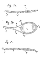
- FIG. 1b shows the same ball racket in an oblique view, in which a possible selection of the cross-sectional profiles is shown as an example. Covering and support frame profiles appear as one unit in adjacent areas.
- Fig. 2a shows a basic form of vibration
- the support frame as the outer frame 1 with handle 2 has two vibration nodes (symmetrical bend), while the inner covered frame 4 undergoes an opposite symmetrical bending deflection relative to the support frame 1, 2 via the articulated connections 5. Both frame parts deform so that the center of gravity remains for the ball racket in the racket plane.
- Fig. 2b shows the next higher "in-plane" basic waveform in the racket plane, both frames undergoing an elastic bending deformation.
- axial relative movements of both frames at the articulation points are possible with this type of vibration, since they are inherent.
- the outer frame 1 with handle part 2 is a quasi-antimetric Bending shape with three vibration nodes
- the inner frame 4 is also symmetrically and oppositely deflected by the articulation 5 in this vibration form.
- This fundamental form of vibration is preferably excited, for example in the case of balls hitting centrically. With this basic vibration, the grip area 2 experiences a relatively small deflection, which is the aim.
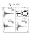
- FIGS. 1a, b and 3c show the response behavior of the ball racket shown in FIGS. 1a, b and 3c in the time course ("time history") over the analysis period of 0.8 sec with 80 time steps and an impressed Dirac impact.
- the damped vibration curves were obtained by FEM simulation at the "Impact" in the center of the club face. While the transverse initial deflection (z) in FIG. 3a is -1.1 mm, the longitudinal deflection (x) shown in FIG. 3b in the racket plane is four orders of magnitude smaller and thus practically vanishes, as is the "in-plane" deflection ( y) in the transverse direction with three powers of ten difference.
- FIG. 3a, b, d have in common that the basic waveform shown in Fig. 2c is excited and that the decay behavior of the fanned vibrations is extremely good, ie more than material-related, damped.
- selected nodes of the support frame at the handle end NODE 19, in the head NODE 3757, in the middle of the side NODE 1949, are selected as representative, as is the node NODE 1975 of the stringing frame, also in the middle of the page. These nodes are also referred to in FIGS. 4a-4d and 5.
- 4a to 4d show the resonance curves of the transverse vibrations (z) from FIG. 3a, but the nodes are separated.
- 4a shows the stretcher deflection over time for the node NODE 1975 in the center of the page.
- the covering frame has the maximum vibration amplitudes (100%).
- Fig. 4b shows at the same position opposite the vibration profile of the support frame node NODE 1949 with about 25% of the maximum amplitude of the stringing frame.
- 4c shows the vibration variation of the node NODE 19 at the end of the handle, further reduced, as well as the vibration in the support frame head node NODE 3757.
- FIG. 5 is an enlarged representation of the images from FIG. 3a and represents the summary of the transverse vibrations of FIGS. 4a to 4d.
- the different temporally decaying amplitudes of the representative nodes can be seen in a direct comparison.
- the opposite phases of the vibrations of the covering and support frame are identifiable, as are identical zero crossings and the exponentially strong decay of the vibrations, overlaid by moderate beats with about a quarter of the resonance frequency.
- Fig. 6a to 6d schematically show in plan view a selection of possible modifications of the ball racket according to the invention.
- Fig. 6a designated as "Type 1" corresponds to the ball racket shown in Fig. 1a, b.
- Characteristic is the arrangement of the joints 5, which connect the outer frame 1 with the grip part 2 and the inner frame 4 in such a way that three local axes of rotation 7, which penetrate the two frames here approximately perpendicularly, arise, which have a common intersection point A in the area of the inner frame 4 within easy reach exhibit.
- Fig. 6b shows a similar, referred to as "type 2" arrangement of the joints 5 as in Fig.
- FIG. 6c shows a modification of the arrangement of the "type 2" of FIG. 6b, in which two local axes of rotation 7 perpendicular to each other are created.
- the configuration shown is designated as "Type 3", since both joints 5 on the handle side are positioned in the extreme region of the covering frame 4. In the borderline case, the two handles on the handle side practically coincide, so that there is only one joint 5 in the head and one opposite on the longitudinal axis of the racket.
- the hinge 5 on the handle would then have an axis of rotation 7 running tangentially to the inner frame 4, the axis intersection A being located on the handle end of the inner frame.
- 6d shows a ball racket according to the invention, designated as "Type 4".
- a ball racket of this type has four articulation points 5 which are located in pairs in extreme positions on the inner frame 4 and along and across the outer frame 1.
- the four articulation points 5 form two mutually perpendicular axes of rotation 7, the common axis intersection A coming to lie in the area of the stringing center.
- Fig. 7 shows a top view of another embodiment of the ball racket according to the invention with two articulation points 5 located on the outer frame 1 and inner frame 4 at the extremity on the head and handle side inner frame area, two mutually parallel axes of rotation 7 being formed which perpendicularly penetrate the longitudinal axis of the racket.
- two articulation points 5 located on the outer frame 1 and inner frame 4 at the extremity on the head and handle side inner frame area, two mutually parallel axes of rotation 7 being formed which perpendicularly penetrate the longitudinal axis of the racket.
- opposing deflections of support frame 1, 2 and covering frame 4 result, as can be seen in FIG. 8.
- a ball racket according to this embodiment also has good ball reflectivity.
- FIG. 9 shows a ball racket according to a further embodiment of the invention.
- this ball racket two articulation points 5 with two axes of rotation 7 in the head area and one articulation point 5 in the forked handle-side area of the support frame 1, 2 and stringing frame 4 are penetrated perpendicular to the longitudinal axis of the racket.
- the intersection A of the axes of rotation 7 comes to lie in the head region of the covering frame 4.
- FIG. 10 shows a possible embodiment of the "Type 4" ball racket shown schematically and functionally in FIG. 6d.
- the joints 5 are all designed as single-axis swivel joints, for example consisting of bolt-socket pairings. Both axes of rotation 7 intersect approximately centrally in A and are perpendicular to one another.
- FIG. 11 shows a ball racket according to a further exemplary embodiment of the invention.
- the covering frame 4 is completely surrounded by the support frame 1, which has the handle part 2.
- the covering frame 4 is connected to the supporting frame 1 by means of two opposite pivot joints 5, not shown, each pair of opposite pivot joints having a common axis of rotation 7.
- the two axes of rotation 7 run parallel to one another and perpendicular to the longitudinal axis of the racket.
- the axes of rotation 7 lie within the area enclosed by the covering frame 4.
- the spring-damper element consists of a pneumatic or hydraulic damping element 9 and two springs 15.
- the spring-damper element 8 is articulated to the two frames.
- the axes of rotation 7 are arranged approximately in each end quarter of the string frame length.
- FIG. 12 shows the ball racket shown in FIG. 11 in a side view, the relative deflection of the two frames 1 and 4 being evident.
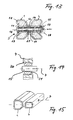
- each frame 1, 4 is reinforced, for example, by a cylindrical section 12 which connects the outer and inner wall sections of the shell 10 to one another.
- a pair of bearing bushes 13 is inserted in the cylindrical section 12 of each frame 1, 4.
- One or more spacers 14 are arranged between the inner bearing bush 13 of the covering frame 4.
- the axis 15 is a simple dowel pin which has a larger flattened head 16 at one end and a bore at the other end through which a cotter pin 17 is inserted for axially securing the dowel pin or the articulated connection.
- a circlip fuse could also be provided.
- a cover cap 18 is optionally provided for covering the inner end of the dowel pin and the cotter pin.
- the pin or bolt length is selected so that in the case of bending deformation in the plane of the racket, such as, for example in the case of longitudinal vibrations, the covering and / or the support frame can slide by transverse contraction in the longitudinal direction of the bolt, so that forced deformations can be reduced.
- a tension-compression spring 19 or a corresponding enclosing elastomer is provided between the two frames 1, 4 in order to improve their axial closure and to exert a supporting and cushioning effect between the frames.
- the spring 19 can also be omitted.
- Fig. 14 shows a simplified representation of a part of a joint 5 in a modification of the embodiment, as a joint with three mutually orthogonal axes of rotation or pivot 7, one of which is shown and coincides with the pin / bolt axis.
- the joint part shown consists of an internally spherical bushing 20, which is fitted in the covering frame 4, and the outer barrel-shaped joint ring 21 inserted and secured therein.
- the pivotable in the bush 20 hinge ring 21 is penetrated by the pin 15, which is received by the support frame 1, 2, not shown in FIG. 13, so that it can slide in the hinge ring 21 along the axis of rotation 7 without any play.
- the joint sketched in Fig. 14 with three degrees of freedom of rotation can also be used to perform the function according to the invention by other known joint connections, e.g. a ball joint will be replaced.
- a joint is also conceivable, which allows the ball player to subsequently change the orientation of the axis 7 in order to adapt the frequencies and thus the playing characteristics to different stringing areas.
- Such a joint could be designed in such a way that the bushing 20 and the joint ring 21 are fixed against one another by means of a screw, so that the pin 15 and thus the remaining axis of rotation 7 can be aligned.
- the supporting frame 1 has a flat cross section stretched in the racket plane
- the supporting frame 1 has a greater overall height transversely to the racket level than the covering frame 4. Because of these basic principles
- the cross-sectional shape of the support frame 1 is rather stiff against a bend perpendicular to the racket plane, while the covering frame 4 is rather stiff against a bend in the racket plane. Because it has been shown that, due to the longitudinal dimensions of the support frame 1 with handle 2, much more is required on deflection perpendicular to the racket plane than the covering frame 4, the main bending stress of which lies in the racket plane.
- the support frame 1 is chamfered, as can be seen in FIG. 15, as a result of which the gap located between the two frames 1, 4 is designed to be aerodynamically favorable in order to reduce the air resistance of the ball racket perpendicular to the racket plane.
- the profile combination with air gap shown by way of example in FIG. 15 is of particular importance with regard to harmonizing the performance properties.
- the required optimization will be a compromise between "optical weight", strength and mass ratios to fulfill the function according to the invention and aerodynamic drag coefficients.
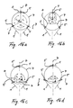
- FIG. 16a to 16d summarize, by way of example, a selection of morphologically obtained possibilities for arranging the three-joint design of the "type 1" according to FIG. 6a.
- different orientations of the axes of rotation 7 and positions of the axis intersection A are shown, which make it possible, with an otherwise identical design of the ball racket or the support frame 1, 2 and the covering frame 4, to constructively set the desired individual playing characteristics.
- Fig. 16a shows an arrangement of the three joints 5 between the support frame 1 and covering frame 4, in which the axes are aligned so that the included angles ⁇ 0 are equal (120 degrees).
- the intersection A of the axes 7 lies in the central covering frame area.
- Fig. 16b shows a similar arrangement as in Fig.
- Fig. 16c shows a modification of Fig. 16b an arrangement of the joints 5, in which the intersection of the axes A lies in the handle-side covering surface area and an angle ⁇ 2 and two angles ⁇ 2 (greater than 90 degrees) are included by the axes 7.
- Fig. 16d differs from Fig. 16c in that the intersection A of the axes 7 migrates against the frame 4 or outside the same and the two included angles ⁇ 3 between the axes 7 are consequently less than 90 degrees.
Landscapes
- Health & Medical Sciences (AREA)
- General Health & Medical Sciences (AREA)
- Physical Education & Sports Medicine (AREA)
- Golf Clubs (AREA)
- Pivots And Pivotal Connections (AREA)
- Laminated Bodies (AREA)
- Compositions Of Macromolecular Compounds (AREA)
- Vibration Prevention Devices (AREA)
Applications Claiming Priority (2)
| Application Number | Priority Date | Filing Date | Title |
|---|---|---|---|
| DE4014999 | 1990-05-10 | ||
| DE4014999A DE4014999C2 (de) | 1990-05-10 | 1990-05-10 | Ballschläger, insbesondere Tennisschläger |
Publications (2)
| Publication Number | Publication Date |
|---|---|
| EP0455885A1 true EP0455885A1 (fr) | 1991-11-13 |
| EP0455885B1 EP0455885B1 (fr) | 1996-10-02 |
Family
ID=6406116
Family Applications (1)
| Application Number | Title | Priority Date | Filing Date |
|---|---|---|---|
| EP90125299A Expired - Lifetime EP0455885B1 (fr) | 1990-05-10 | 1990-12-21 | Raquette pour jeux de balles, en particulier raquette de tennis |
Country Status (9)
| Country | Link |
|---|---|
| US (1) | US5178388A (fr) |
| EP (1) | EP0455885B1 (fr) |
| JP (1) | JPH05507009A (fr) |
| AT (1) | ATE143611T1 (fr) |
| AU (1) | AU7854991A (fr) |
| CA (1) | CA2082513A1 (fr) |
| DE (2) | DE4014999C2 (fr) |
| HU (2) | HUT66898A (fr) |
| WO (1) | WO1991016950A1 (fr) |
Cited By (5)
| Publication number | Priority date | Publication date | Assignee | Title |
|---|---|---|---|---|
| WO2008068714A1 (fr) * | 2006-12-08 | 2008-06-12 | European Sports Merchandising Bv | Raquette |
| WO2009068178A1 (fr) * | 2007-11-26 | 2009-06-04 | Head Technology Gmbh | Raquette à articulation |
| WO2014152205A1 (fr) * | 2013-03-15 | 2014-09-25 | Zarda Paul Richard Jr | Raquette de tennis dotée d'une isolation réglable de cadre |
| US11141630B2 (en) | 2013-03-15 | 2021-10-12 | Paul Richard Zarda, JR. | Tennis racquet with adjustable frame isolation |
| CN113975762A (zh) * | 2020-07-26 | 2022-01-28 | 杨履方 | 多圈球拍 |
Families Citing this family (5)
| Publication number | Priority date | Publication date | Assignee | Title |
|---|---|---|---|---|
| US5560600A (en) * | 1995-01-05 | 1996-10-01 | Fitzsimons; E. Luke | Method for and racket to teach tennis |
| NL1020131C1 (nl) * | 2002-03-07 | 2003-09-10 | Govert De Vries | Werkwijze en inrichting voor het meten en presenteren van parameters bij het met behulp van een slagwerktuig slaan tegen een te verplaatsen voorwerp. |
| US7736251B2 (en) * | 2004-07-26 | 2010-06-15 | Quikstick Lacrosse, Llc | Lacrosse stick |
| US8814731B2 (en) | 2012-06-06 | 2014-08-26 | Joseph Jennings | Flexible racquet handle |
| US8608596B1 (en) * | 2012-11-29 | 2013-12-17 | Cheng-Chung Chang | Racket with a movable throat |
Citations (3)
| Publication number | Priority date | Publication date | Assignee | Title |
|---|---|---|---|---|
| GB431394A (en) * | 1934-01-04 | 1935-07-04 | Frank Wordsworth Donisthorpe | Improvements in or relating to rackets or bats for tennis and like games |
| FR2581317A1 (fr) * | 1985-05-03 | 1986-11-07 | Mussat Frederic | Raquette a double cadre mobile |
| EP0207308A2 (fr) * | 1985-06-05 | 1987-01-07 | Shozo Kurusu | Raquettes de sport |
Family Cites Families (8)
| Publication number | Priority date | Publication date | Assignee | Title |
|---|---|---|---|---|
| DE8225195U1 (de) * | 1982-12-23 | Hällmayer, Freduardt, 8306 Schierling | Schläger für Ballspiele | |
| DE1954912A1 (de) * | 1969-10-28 | 1971-07-15 | Nagel Dieter Dipl Ing | Ballschlaeger mit wechselbarer vorgefertigter Schlagflaeche |
| US4094505A (en) * | 1977-01-04 | 1978-06-13 | Beall Jr Thomas E | Tennis racket |
| DE3038709A1 (de) * | 1980-10-13 | 1982-05-27 | Paar, Kurt, 8100 Garmisch-Partenkirchen | Ballschlaeger mit auswechselbarem bespannungs-rahmen |
| SU1227214A1 (ru) * | 1984-05-30 | 1986-04-30 | Рижский Краснознаменный Институт Инженеров Гражданской Авиации Им.Ленинского Комсомола | Тренировочна ракетка |
| US4581965A (en) * | 1985-05-17 | 1986-04-15 | Gerber Scientific, Inc. | Apparatus and related method for cutting and dedusting sheet material |
| US4915382A (en) * | 1988-06-06 | 1990-04-10 | Madsen Erik H | Compactible tennis racquet |
| US5002278A (en) * | 1989-11-13 | 1991-03-26 | Costa Juan C | Racket |
-
1990
- 1990-05-10 DE DE4014999A patent/DE4014999C2/de not_active Expired - Fee Related
- 1990-12-21 AT AT90125299T patent/ATE143611T1/de not_active IP Right Cessation
- 1990-12-21 EP EP90125299A patent/EP0455885B1/fr not_active Expired - Lifetime
- 1990-12-21 DE DE59010526T patent/DE59010526D1/de not_active Expired - Fee Related
-
1991
- 1991-05-06 US US07/695,922 patent/US5178388A/en not_active Expired - Fee Related
- 1991-05-07 JP JP91508735A patent/JPH05507009A/ja active Pending
- 1991-05-07 CA CA002082513A patent/CA2082513A1/fr not_active Abandoned
- 1991-05-07 AU AU78549/91A patent/AU7854991A/en not_active Abandoned
- 1991-05-07 HU HU9203509A patent/HUT66898A/hu unknown
- 1991-05-07 WO PCT/EP1991/000855 patent/WO1991016950A1/fr not_active Ceased
- 1991-05-07 HU HU923509V patent/HU9203509D0/hu unknown
Patent Citations (3)
| Publication number | Priority date | Publication date | Assignee | Title |
|---|---|---|---|---|
| GB431394A (en) * | 1934-01-04 | 1935-07-04 | Frank Wordsworth Donisthorpe | Improvements in or relating to rackets or bats for tennis and like games |
| FR2581317A1 (fr) * | 1985-05-03 | 1986-11-07 | Mussat Frederic | Raquette a double cadre mobile |
| EP0207308A2 (fr) * | 1985-06-05 | 1987-01-07 | Shozo Kurusu | Raquettes de sport |
Non-Patent Citations (1)
| Title |
|---|
| SOVIET INVENTIONS ILLUSTRATED P,Q section, week 8651, February 4, 1987 DERWENT PUBLICATIONS LTD. page 36 & SU-A-1227 214 (RIAV). * |
Cited By (10)
| Publication number | Priority date | Publication date | Assignee | Title |
|---|---|---|---|---|
| WO2008068714A1 (fr) * | 2006-12-08 | 2008-06-12 | European Sports Merchandising Bv | Raquette |
| WO2009068178A1 (fr) * | 2007-11-26 | 2009-06-04 | Head Technology Gmbh | Raquette à articulation |
| US8282513B2 (en) | 2007-11-26 | 2012-10-09 | Head Technology Gmbh | Racket comprising a joint |
| CN101896234B (zh) * | 2007-11-26 | 2013-04-10 | 黑德技术有限公司 | 具有活节的球拍 |
| WO2014152205A1 (fr) * | 2013-03-15 | 2014-09-25 | Zarda Paul Richard Jr | Raquette de tennis dotée d'une isolation réglable de cadre |
| US9975009B2 (en) | 2013-03-15 | 2018-05-22 | Paul Richard Zarda, JR. | Tennis racquet with adjustable frame isolation |
| US10369424B2 (en) | 2013-03-15 | 2019-08-06 | Paul Richard Zarda, JR. | Tennis racquet with adjustable frame isolation |
| US10561906B2 (en) | 2013-03-15 | 2020-02-18 | Paul Richard Zarda, JR. | Tennis racquet with adjustable frame isolation |
| US11141630B2 (en) | 2013-03-15 | 2021-10-12 | Paul Richard Zarda, JR. | Tennis racquet with adjustable frame isolation |
| CN113975762A (zh) * | 2020-07-26 | 2022-01-28 | 杨履方 | 多圈球拍 |
Also Published As
| Publication number | Publication date |
|---|---|
| DE59010526D1 (de) | 1996-11-07 |
| ATE143611T1 (de) | 1996-10-15 |
| HU9203509D0 (en) | 1993-04-28 |
| US5178388A (en) | 1993-01-12 |
| HUT66898A (en) | 1995-01-30 |
| WO1991016950A1 (fr) | 1991-11-14 |
| CA2082513A1 (fr) | 1991-11-11 |
| DE4014999A1 (de) | 1991-11-14 |
| DE4014999C2 (de) | 1993-12-02 |
| JPH05507009A (ja) | 1993-10-14 |
| AU7854991A (en) | 1991-11-27 |
| EP0455885B1 (fr) | 1996-10-02 |
Similar Documents
| Publication | Publication Date | Title |
|---|---|---|
| DE68928107T2 (de) | Sportschläger | |
| DE3928907C2 (de) | Tennisschläger | |
| DE3434898C2 (fr) | ||
| EP0455885B1 (fr) | Raquette pour jeux de balles, en particulier raquette de tennis | |
| DE2546028A1 (de) | Tennisschlaeger | |
| WO2007088070A2 (fr) | Raquette | |
| DE3826545A1 (de) | Tennisschlaeger | |
| EP1127983A2 (fr) | Plaque vibrante | |
| EP0397832B1 (fr) | Raquette pour jeux de balle | |
| EP2062621B1 (fr) | Raquette dotée d'un pont mobile | |
| EP0468263B1 (fr) | Raquette pour jeux de balles, en particulier raquette de tennis | |
| EP1557204B1 (fr) | Raquette pour jeux de balle et méthode de fabrication | |
| DE4037928A1 (de) | Prothesenfuss | |
| DE69806488T2 (de) | Mit oszillierenden vibrationsdäpfungselementen ausgestatteter tennisschläger | |
| EP2219743B1 (fr) | Raquette à articulation | |
| DE102006004849B4 (de) | Ballspielschläger mit Schwingungseinrichtung | |
| DE3428528A1 (de) | Tennisschlaegergriff | |
| EP1154822B1 (fr) | Raquette pour jeu de balle | |
| DE19935390A1 (de) | Ballspielschläger | |
| EP2138207B1 (fr) | Batteur de jeux de balle | |
| AT408724B (de) | Einrichtung zum dämpfen von vibrationen eines ballschlägers | |
| DE4311175A1 (de) | Ballschläger, insbesondere Tennisschläger | |
| DE102006004863A1 (de) | Schläger für Ballspiele | |
| DE9100325U1 (de) | Saitenbespannbarer Schläger zum Spielen von Bällen, insbesondere Tennis-, Squash-Schläger o.dgl. | |
| EP0301530B1 (fr) | Raquette, en particulier pour tennis |
Legal Events
| Date | Code | Title | Description |
|---|---|---|---|
| PUAI | Public reference made under article 153(3) epc to a published international application that has entered the european phase |
Free format text: ORIGINAL CODE: 0009012 |
|
| AK | Designated contracting states |
Kind code of ref document: A1 Designated state(s): AT BE CH DE ES FR GB GR IT LI NL SE |
|
| 17P | Request for examination filed |
Effective date: 19920512 |
|
| 17Q | First examination report despatched |
Effective date: 19931026 |
|
| GRAH | Despatch of communication of intention to grant a patent |
Free format text: ORIGINAL CODE: EPIDOS IGRA |
|
| GRAA | (expected) grant |
Free format text: ORIGINAL CODE: 0009210 |
|
| AK | Designated contracting states |
Kind code of ref document: B1 Designated state(s): AT BE CH DE ES FR GB GR IT LI NL SE |
|
| PG25 | Lapsed in a contracting state [announced via postgrant information from national office to epo] |
Ref country code: IT Free format text: LAPSE BECAUSE OF FAILURE TO SUBMIT A TRANSLATION OF THE DESCRIPTION OR TO PAY THE FEE WITHIN THE PRE;WARNING: LAPSES OF ITALIAN PATENTS WITH EFFECTIVE DATE BEFORE 2007 MAY HAVE OCCURRED AT ANY TIME BEFORE 2007. THE CORRECT EFFECTIVE DATE MAY BE DIFFERENT FROM THE ONE RECORDED.SCRIBED TIME-LIMIT Effective date: 19961002 Ref country code: GR Free format text: LAPSE BECAUSE OF FAILURE TO SUBMIT A TRANSLATION OF THE DESCRIPTION OR TO PAY THE FEE WITHIN THE PRESCRIBED TIME-LIMIT Effective date: 19961002 Ref country code: GB Effective date: 19961002 Ref country code: ES Free format text: THE PATENT HAS BEEN ANNULLED BY A DECISION OF A NATIONAL AUTHORITY Effective date: 19961002 Ref country code: NL Free format text: LAPSE BECAUSE OF FAILURE TO SUBMIT A TRANSLATION OF THE DESCRIPTION OR TO PAY THE FEE WITHIN THE PRESCRIBED TIME-LIMIT Effective date: 19961002 |
|
| REF | Corresponds to: |
Ref document number: 143611 Country of ref document: AT Date of ref document: 19961015 Kind code of ref document: T |
|
| REF | Corresponds to: |
Ref document number: 59010526 Country of ref document: DE Date of ref document: 19961107 |
|
| PG25 | Lapsed in a contracting state [announced via postgrant information from national office to epo] |
Ref country code: CH Effective date: 19961231 Ref country code: LI Effective date: 19961231 Ref country code: BE Effective date: 19961231 |
|
| PG25 | Lapsed in a contracting state [announced via postgrant information from national office to epo] |
Ref country code: SE Effective date: 19970102 |
|
| PGFP | Annual fee paid to national office [announced via postgrant information from national office to epo] |
Ref country code: DE Payment date: 19970226 Year of fee payment: 7 |
|
| ET | Fr: translation filed | ||
| NLV1 | Nl: lapsed or annulled due to failure to fulfill the requirements of art. 29p and 29m of the patents act | ||
| GBV | Gb: ep patent (uk) treated as always having been void in accordance with gb section 77(7)/1977 [no translation filed] |
Effective date: 19961002 |
|
| PLBE | No opposition filed within time limit |
Free format text: ORIGINAL CODE: 0009261 |
|
| STAA | Information on the status of an ep patent application or granted ep patent |
Free format text: STATUS: NO OPPOSITION FILED WITHIN TIME LIMIT |
|
| REG | Reference to a national code |
Ref country code: CH Ref legal event code: PL |
|
| 26N | No opposition filed | ||
| PG25 | Lapsed in a contracting state [announced via postgrant information from national office to epo] |
Ref country code: DE Free format text: LAPSE BECAUSE OF NON-PAYMENT OF DUE FEES Effective date: 19980901 |
|
| PGFP | Annual fee paid to national office [announced via postgrant information from national office to epo] |
Ref country code: AT Payment date: 20000629 Year of fee payment: 10 |
|
| PG25 | Lapsed in a contracting state [announced via postgrant information from national office to epo] |
Ref country code: AT Free format text: LAPSE BECAUSE OF NON-PAYMENT OF DUE FEES Effective date: 20001221 |
|
| PGFP | Annual fee paid to national office [announced via postgrant information from national office to epo] |
Ref country code: FR Payment date: 20001227 Year of fee payment: 11 |
|
| PG25 | Lapsed in a contracting state [announced via postgrant information from national office to epo] |
Ref country code: FR Free format text: LAPSE BECAUSE OF NON-PAYMENT OF DUE FEES Effective date: 20020830 |
|
| REG | Reference to a national code |
Ref country code: FR Ref legal event code: ST |