EP0455897B1 - Dispositif pour la fabrication de fibres trés fines - Google Patents
Dispositif pour la fabrication de fibres trés fines Download PDFInfo
- Publication number
- EP0455897B1 EP0455897B1 EP90250121A EP90250121A EP0455897B1 EP 0455897 B1 EP0455897 B1 EP 0455897B1 EP 90250121 A EP90250121 A EP 90250121A EP 90250121 A EP90250121 A EP 90250121A EP 0455897 B1 EP0455897 B1 EP 0455897B1
- Authority
- EP
- European Patent Office
- Prior art keywords
- gas
- bores
- melt
- melting
- spinning
- Prior art date
- Legal status (The legal status is an assumption and is not a legal conclusion. Google has not performed a legal analysis and makes no representation as to the accuracy of the status listed.)
- Expired - Lifetime
Links
- 238000009987 spinning Methods 0.000 claims abstract description 32
- 238000004519 manufacturing process Methods 0.000 claims abstract description 12
- 238000007664 blowing Methods 0.000 claims description 16
- 238000009826 distribution Methods 0.000 claims description 14
- 238000010438 heat treatment Methods 0.000 claims description 6
- 239000007789 gas Substances 0.000 claims 10
- 230000008018 melting Effects 0.000 claims 7
- 238000002844 melting Methods 0.000 claims 7
- 239000000155 melt Substances 0.000 abstract description 30
- 238000000034 method Methods 0.000 abstract description 2
- 239000003570 air Substances 0.000 description 28
- 239000000835 fiber Substances 0.000 description 13
- 238000010276 construction Methods 0.000 description 3
- 238000001816 cooling Methods 0.000 description 3
- 238000013461 design Methods 0.000 description 3
- 239000004744 fabric Substances 0.000 description 3
- 239000004753 textile Substances 0.000 description 3
- 238000012546 transfer Methods 0.000 description 3
- 238000004804 winding Methods 0.000 description 3
- 229920001410 Microfiber Polymers 0.000 description 2
- QAOWNCQODCNURD-UHFFFAOYSA-N Sulfuric acid Chemical compound OS(O)(=O)=O QAOWNCQODCNURD-UHFFFAOYSA-N 0.000 description 2
- 239000012080 ambient air Substances 0.000 description 2
- 230000015572 biosynthetic process Effects 0.000 description 2
- 238000005516 engineering process Methods 0.000 description 2
- 238000005755 formation reaction Methods 0.000 description 2
- 238000009413 insulation Methods 0.000 description 2
- 239000000463 material Substances 0.000 description 2
- 239000003658 microfiber Substances 0.000 description 2
- 238000003825 pressing Methods 0.000 description 2
- MHCVCKDNQYMGEX-UHFFFAOYSA-N 1,1'-biphenyl;phenoxybenzene Chemical group C1=CC=CC=C1C1=CC=CC=C1.C=1C=CC=CC=1OC1=CC=CC=C1 MHCVCKDNQYMGEX-UHFFFAOYSA-N 0.000 description 1
- 239000004952 Polyamide Substances 0.000 description 1
- 239000004743 Polypropylene Substances 0.000 description 1
- 238000010521 absorption reaction Methods 0.000 description 1
- 229910052782 aluminium Inorganic materials 0.000 description 1
- XAGFODPZIPBFFR-UHFFFAOYSA-N aluminium Chemical compound [Al] XAGFODPZIPBFFR-UHFFFAOYSA-N 0.000 description 1
- 239000012876 carrier material Substances 0.000 description 1
- 238000004140 cleaning Methods 0.000 description 1
- 238000006073 displacement reaction Methods 0.000 description 1
- 230000000694 effects Effects 0.000 description 1
- 238000001914 filtration Methods 0.000 description 1
- 230000005484 gravity Effects 0.000 description 1
- 239000007788 liquid Substances 0.000 description 1
- 238000012423 maintenance Methods 0.000 description 1
- 238000002074 melt spinning Methods 0.000 description 1
- 229910052751 metal Inorganic materials 0.000 description 1
- 239000002184 metal Substances 0.000 description 1
- 238000002156 mixing Methods 0.000 description 1
- 239000004033 plastic Substances 0.000 description 1
- 229920002647 polyamide Polymers 0.000 description 1
- 229920000642 polymer Polymers 0.000 description 1
- -1 polypropylene Polymers 0.000 description 1
- 229920001155 polypropylene Polymers 0.000 description 1
- 238000012545 processing Methods 0.000 description 1
- 239000002994 raw material Substances 0.000 description 1
- 238000011160 research Methods 0.000 description 1
- 229920001169 thermoplastic Polymers 0.000 description 1
- 239000004416 thermosoftening plastic Substances 0.000 description 1
- 230000007704 transition Effects 0.000 description 1
Images
Classifications
-
- D—TEXTILES; PAPER
- D01—NATURAL OR MAN-MADE THREADS OR FIBRES; SPINNING
- D01D—MECHANICAL METHODS OR APPARATUS IN THE MANUFACTURE OF ARTIFICIAL FILAMENTS, THREADS, FIBRES, BRISTLES OR RIBBONS
- D01D4/00—Spinnerette packs; Cleaning thereof
- D01D4/02—Spinnerettes
- D01D4/025—Melt-blowing or solution-blowing dies
-
- D—TEXTILES; PAPER
- D01—NATURAL OR MAN-MADE THREADS OR FIBRES; SPINNING
- D01D—MECHANICAL METHODS OR APPARATUS IN THE MANUFACTURE OF ARTIFICIAL FILAMENTS, THREADS, FIBRES, BRISTLES OR RIBBONS
- D01D5/00—Formation of filaments, threads, or the like
- D01D5/08—Melt spinning methods
- D01D5/098—Melt spinning methods with simultaneous stretching
- D01D5/0985—Melt spinning methods with simultaneous stretching by means of a flowing gas (e.g. melt-blowing)
Definitions
- the invention relates to a device for producing fine threads according to the preamble of the main claim.
- the arrangement of the melt bores in a row with an overlying distribution channel and air outlet slots lying close to the bores is basically a weak construction, both in terms of the deformation of the slot by the air pressure - 0.5 to 6 bar and above are used - as well as the deformation of the elongated melt distribution space.
- U.S. Patent No. 4,486,161 a device of this type is protected in which the opposing melt walls are connected by webs in order to increase the resistance to inflation.
- a spinning head which has a first plate connected to the melt feed and a second plate also fastened, a gas distribution space being provided between the two plates and being connected to a gas feed.
- a plurality of nozzle elements are screwed into the second plate, the melt bores connected on the one hand with the melt supply and on the other hand into the gas distribution space have opening channels for the emerging threads or fibers surrounding gas streams.
- the nozzle elements consist of several parts, so that the structure is complicated.
- US-A-3 954 361 describes a device for producing threads from a melt-spinnable plastic material which has a spinning head surrounding a melt chamber, in which a plurality of tubes are inserted in a row, which protrude beyond the lower end of the head. Around the head are at a distance from this. two air duct walls are arranged, which have a slot receiving the row of tubes. The air flows through the air duct and to the outside between the tubes and air duct walls spinning the threads.
- the invention has for its object to provide a device for producing fine threads, the one hand continuous fine threads or fibers without thread breaks with a diameter between 5 to 10 microns or particularly thin threads in the range against 1 micron, the do not have to be endless, can supply and which have an improved distribution of the gas or air flow with respect to the individual threads emerging from the spinning head and allow a higher melt throughput, the construction of the spinning head should be simple.
- each Melt thread therefore has its own blowing nozzle.
- the present invention it is possible to produce continuous (or endless) fine threads, as are desired in the textile technology for particularly fine-titer yarns for the production of women's stockings or fine capillary fabrics with high thermal insulation and at the same time possible moisture transport for good physiological wearing properties.
- the single thread of a yarn composed of several such should have a fineness of less than 1 denier per filament.
- 1 denier (den) is the weight of a thread of length 9,000 m
- decitex decitex
- the weight in g also refers to 10,000 m thread length.
- each bore or spinning opening in the spinneret is assigned an individual blowing nozzle, the blowing nozzles being connected to a gas supply, gives a very good gas distribution with respect to the individual threads. Since the gas flow is applied evenly to the threads, there are no thread breaks and the diameter of the threads after they have cooled is essentially constant.
- the design of the spinnerets is not as limited in the design and construction of the spinning heads as in the prior art, in which only a limited number of spinning orifices can be provided.
- the design of the spinning head is very simple and inexpensive due to the specially designed plates with the elevations engaging in bores.
- meltblown fibers that have been used in many areas such as filtration, absorption and insulation in technical, medical, textile tasks.
- the difference to the production of continuous or endless threads is that generally higher melt temperatures and above all higher air velocities, ie also air pressures, are used to avoid high shear stresses to pull out the thread to the appropriate fineness.
- melt temperatures and above all higher air velocities ie also air pressures
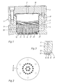
- the spin pack 1 shown in FIG. 1 is part of a spinning head which is used for pressing thermoplastic melts in the production of blow-spun threads.
- the spin pack is connected via a melt line 2 to a pump part, not shown.
- the spin pack has a housing consisting of two parts 3, 4 which are screwed together: in the lower part of the housing 3, 4 there is a spinneret 5, which is described in more detail below.
- a large number of melt bores 6 lying next to one another are provided in the spinneret 5.
- a support plate 7 is supported on the spinneret, which has a plurality of through holes 8 for passing the melt through.
- a filter unit 9 is located above the support plate 7 and a displacement body 10 is arranged above it, which defines a specific space for the passage of the melt entering via the melt line 2.
- the melt flow during the transition from one component to the other is sealed by soft metal seals such as aluminum.
- the spinneret 5 which for the sake of clarity is shown in FIG. 1 only with a few melt bores 6 not to scale, FIG. 3 showing a section, has a circular cross section and consists of two plates 11, 12 which are screwed together.
- the upper plate 11, which is provided with the melt bores 6, has a plurality of conical elevations 13 around the melt bores 6.
- the lower plate 12 is designed in such a way that it has conical openings 14 which correspond to the elevations 13, the elevations 13 projecting into the conical openings 14 when the plates 11, 12 are screwed together, so that there is between the outer surface of the elevations 13 and the inner surface of the conical bores 14 each form an annular channel or an annular gap.
- the arrangement consisting of the inner surface of the bore 14 surrounding the melt bore 6 and the annular outer surface of the elevation 13 located in the lower counterplate 12, form a blow nozzle 16.
- the individual blow nozzles 16 surrounding the melt bore 6 are connected to a gas distribution space 17 which by appropriate Formations between the plates 11 and 12 is formed.
- the cross section for the inflow to the individual blowing nozzles 16 is several times larger than the cross section of the annular gap 15 for the purpose of the best possible distribution.
- the gas (air) can be heated directly in the spinning head.
- spinnerets are heated by a liquid or vaporous organic heat transfer medium, the temperature of which is that of the desired melt temperature.
- the gas supply lines can be guided in the spinning head and the gas can also be brought to melt temperature if a sufficiently large heat transfer area is provided. This leads to a particularly compact and simple control device. However, no variations in the gas temperature above or below the melt temperature are then possible.
- the hot gas flows concentrically surrounding the melt bore 6 and leaving the blowing nozzle 16 facilitate the warping of the thread to thinner diameters, which are distorted by gravity, but especially by the tensile forces exerted by the winding unit, and are molecularly oriented depending on the speed.
- the hot gas jet mixes with the ambient air and takes on an increasingly lower mixing temperature.
- the melt temperature of the spun polymeric or other thread-forming raw material falls below, the thread begins to solidify to its final diameter. Finer threads can be achieved in that the throughput is reduced at the same winding speed and, if breaks occur, the air and melt temperature are increased, which is possible up to a certain limit.
- meltblown fine fibers For the production of meltblown fine fibers, a gas heater, mostly electrically heated, which is independent of the temperature of the spinning head is used, through which the gas flows and is then no longer fed through the heating chamber of the spinning head to the nozzle. This can be done constructively in the same way as shown in FIG. 1. Another possibility is to lead the heated gas to the side of the spinneret and then to connect it to the spinneret with the melt opening arranged at the side by pressing against the melt and gas openings with seals. The gas temperature can then be significantly higher than the melt temperature, which produces finer fibers.
- melt-blown fine fibers mostly in the range significantly below 10 ⁇ m and definitely below 1 ⁇ m, are usually deposited in a random form as a fleece.
- the gas flows from the blowing nozzles 16, mixed with the ambient air below the spinnerets, flow laterally or flow through the fleece.
- the fleece made of fine fibers or threads can also be spun directly onto a carrier material.
- the device according to the invention avoids the disadvantages known hitherto, in which the narrow, flat air gap has to be readjusted after each nozzle cleaning.
- this gap arises automatically if only an accuracy that can be achieved with today's machine tools was pursued in the manufacture of the two halves 11 and 12, that is to say the melt bore 6 and the conical bore 14 have the same center with sufficient tolerance.
- a deviation of a few hundredths of a millimeter is permissible for Annular gaps 15 from 0.2 to 0.6 mm.
- one will use the same material for the two parts 11 and 12, so that there are no different thermal expansions.
- the two parts are fitted with fits on the edges using the usual toolmaking technology.
- the spinning bores 6 and the blowing nozzles 16 surrounding them are arranged distributed on a circular cross section.
- the melt bores 6 can be distributed as desired on a nozzle face. 2 this was shown for a circular nozzle, the individual melt bores 6 and thus also the blowing nozzles 16 being arranged on concentric circles. But they can also be arranged in a row, with the advantage of more precise maintenance of the air gap compared to the previous devices, or in several rows next to each other.
- Such multi-row longitudinal nozzles with a large number of holes are recommended for the production of fine or microfibers, which are collected as a fleece, while round nozzles can be used for the production of endless textile fine threads for later processing in fabrics or knitted fabrics. So it is also conceivable that in this way cables are made from the finest threads that are later cut into staple fibers. Both round and rectangular nozzles are to be used.
- the principle of the invention is not limited to the shape of the nozzle.
- the spinning head had air tubes which led through a heating room heated with diphyl steam and ended in the fastening surface of the spinning pack.
- a spinneret with a diameter of 60 mm was screwed into the spin pack 1, which had the characteristics according to the invention essentially according to FIG. 1.
- the number of holes in the nozzles was 12 and the diameter of the melt bore was 0.25 mm.
- the lower part 12 of the spinneret formed 14 annular gaps 15 of 0.4 mm width with the cone of the spinning bores 14.
- the temperature of the polyamide melt was 228 ° C. and the air fed to the spinneret was practically the same temperature.
- the air volume was 1.8 Nm3 / h.
- the amount of melt distributed over the twelve holes was 3 g / min.
- the arrangement corresponded to the usual melt spinning device for synthetic threads.
- a blow chute in which air of 25 ° C and 40% rel. Moisture was blown in at a speed of 0.3 m / s to cool the threads.
- the threads were wound up by a high-speed winder at a speed of 5540 m / min.
- the titer was 12 x 0.45 dtex, which corresponds to a diameter of the individual capillary of approximately 7.2 ⁇ m.
- the average diameter of the fibers was 4 to 5 ⁇ m, with the smallest of 2 ⁇ m and the largest of 6 ⁇ m.
- the determination of the thread diameter was carried out on a microscope.
Landscapes
- Engineering & Computer Science (AREA)
- Mechanical Engineering (AREA)
- Textile Engineering (AREA)
- Spinning Methods And Devices For Manufacturing Artificial Fibers (AREA)
- Yarns And Mechanical Finishing Of Yarns Or Ropes (AREA)
Claims (7)
- Dispositif pour la fabrication de fils extra-fins à l'aide d'un ensemble de filage qui comporte une filière (5) pourvue d'une pluralité de trous de passage (6) du produit fondu et qui est constituée par deux plaques (11, 12) pouvant être réunies entre elles et entre lesquelles est ménagée une chambre de répartition du gaz (17), une buse de soufflage individuelle en communication systématique avec la chambre de répartition du gaz étant adjointe à chaque trou de passage (6), caractérisé en ce que ladite plaque (11) est pourvue des trous de passage du produit fondu et munie de bossages (13) s'étendant à travers la chambre de répartition du gaz, bossages qui sont également traversés par les trous de passage du produit fondu, et en ce que l'autre plaque (12) présente des trous (14), les bossages (13) de l'une des plaques (11) pénétrant dans les trous (14) de l'autre plaque (12) en ménageant chaque fois un passage annulaire libre (15) en vue de la formation des buses de soufflage (16), de telle manière que les fils sortant des trous de passage (6) du produit fondu soient entourés concentriquement par les jets de gaz envoyés à travers les buses de soufflage (16).
- Dispositif selon la revendication 1, caractérisé en ce que les trous de passage (6) du produit fondu avec leurs buses de soufflage (16) sont répartis régulièrement sur une section transversale circulaire.
- Dispositif selon la revendication 1, caractérisé en ce que les trous de passage (6) du produit fondu avec leurs buses de soufflage (16) sont disposés en long sur au moins une rangée.
- Dispositif selon l'une quelconque des revendications 1 à 3, caractérisé en ce que les trous (14) et les bossages (13) dans les plaques inférieure et supérieure (12, 11) sont réalisés coniquement de manière à former un passage annulaire conique (15).
- Dispositif selon l'une quelconque des revendications 1 à 4, caractérisé en ce que la chambre de répartition du gaz (17) est reliée à des canaux à gaz (18, 19) traversant l'ensemble de filage.
- Dispositif selon l'une quelconque des revendications 1 à 5, caractérisé en ce que les canaux à gaz traversent également la tête de filage et en ce que les gaz qu'ils conduisent sont chauffés par le chauffage de la tête de filage.
- Dispositif selon l'une quelconque des revendications 1 à 6, caractérisé en ce qu'un chauffage électrique complémentaire des gaz est prévu pour le chauffage des jets de gaz.
Priority Applications (4)
| Application Number | Priority Date | Filing Date | Title |
|---|---|---|---|
| AT90250121T ATE93283T1 (de) | 1990-05-09 | 1990-05-09 | Vorrichtung zum herstellen von feinstfaeden. |
| DE9090250121T DE59002398D1 (de) | 1990-05-09 | 1990-05-09 | Vorrichtung zum herstellen von feinstfaeden. |
| EP90250121A EP0455897B1 (fr) | 1990-05-09 | 1990-05-09 | Dispositif pour la fabrication de fibres trés fines |
| JP3102765A JPH04228606A (ja) | 1990-05-09 | 1991-05-08 | 溶融紡糸可能な合成材料の非常に細い糸を製造するための方法及び装置 |
Applications Claiming Priority (1)
| Application Number | Priority Date | Filing Date | Title |
|---|---|---|---|
| EP90250121A EP0455897B1 (fr) | 1990-05-09 | 1990-05-09 | Dispositif pour la fabrication de fibres trés fines |
Publications (2)
| Publication Number | Publication Date |
|---|---|
| EP0455897A1 EP0455897A1 (fr) | 1991-11-13 |
| EP0455897B1 true EP0455897B1 (fr) | 1993-08-18 |
Family
ID=8205229
Family Applications (1)
| Application Number | Title | Priority Date | Filing Date |
|---|---|---|---|
| EP90250121A Expired - Lifetime EP0455897B1 (fr) | 1990-05-09 | 1990-05-09 | Dispositif pour la fabrication de fibres trés fines |
Country Status (4)
| Country | Link |
|---|---|
| EP (1) | EP0455897B1 (fr) |
| JP (1) | JPH04228606A (fr) |
| AT (1) | ATE93283T1 (fr) |
| DE (1) | DE59002398D1 (fr) |
Families Citing this family (14)
| Publication number | Priority date | Publication date | Assignee | Title |
|---|---|---|---|---|
| DE59204574D1 (de) * | 1991-09-06 | 1996-01-18 | Akzo Nobel Nv | Vorrichtung zum Schnellspinnen von multifilen Fäden und deren Verwendung. |
| US5196207A (en) * | 1992-01-27 | 1993-03-23 | Kimberly-Clark Corporation | Meltblown die head |
| BR9400682A (pt) * | 1993-03-05 | 1994-10-18 | Akzo Nv | Aparelho para a fiação em fusão de fios multifilamentares e sua aplicação |
| AT405948B (de) * | 1998-03-26 | 1999-12-27 | Chemiefaser Lenzing Ag | Spinndüse |
| DE102006012052A1 (de) * | 2006-03-08 | 2007-09-13 | Lüder GERKING | Spinnvorrichtung zur Erzeugung feiner Fäden durch Spleißen |
| CN103882535B (zh) * | 2014-04-11 | 2017-05-17 | 天津工业大学 | 一种溶液喷射纺丝模头 |
| JP5946569B1 (ja) * | 2015-04-17 | 2016-07-06 | 紘邦 張本 | メルトブロー用口金及び極細繊維製造装置 |
| JP5946565B1 (ja) * | 2015-06-23 | 2016-07-06 | 紘邦 張本 | 紡糸口金及び極細繊維製造装置 |
| RU2614087C1 (ru) * | 2015-11-18 | 2017-03-22 | Федеральное государственное автономное образовательное учреждение высшего образования "Национальный исследовательский Томский государственный университет" (ТГУ, НИ ТГУ) | Устройство для получения волокнистых материалов из расплава термопластов |
| JP6095089B1 (ja) * | 2016-06-20 | 2017-03-15 | 紘邦 張本 | メルトブロー用口金、これを用いた極細繊維製造装置及びその製造方法 |
| DE102020001132A1 (de) * | 2020-02-20 | 2021-08-26 | Oerlikon Textile Gmbh & Co. Kg | Schmelzblasdüsenvorrichtung |
| DE102022102160A1 (de) * | 2022-01-31 | 2023-08-03 | Oerlikon Textile Gmbh & Co. Kg | Schmelzblasdüsenvorrichtung zur Herstellung einer Vielzahl von Fasersträngen aus einer Polymerschmelze |
| CN115434021B (zh) * | 2022-10-08 | 2024-01-05 | 无锡市兴盛新材料科技有限公司 | 一种优化冷却成形的短纤维直纺工艺 |
| CN118854469A (zh) * | 2024-07-05 | 2024-10-29 | 禾欣可乐丽超纤(海盐)有限公司 | 一种pet超纤合成革生产设备及生产工艺 |
Family Cites Families (8)
| Publication number | Priority date | Publication date | Assignee | Title |
|---|---|---|---|---|
| JPS5224411B1 (fr) * | 1968-12-19 | 1977-07-01 | ||
| US3849241A (en) * | 1968-12-23 | 1974-11-19 | Exxon Research Engineering Co | Non-woven mats by melt blowing |
| US3888610A (en) * | 1973-08-24 | 1975-06-10 | Rothmans Of Pall Mall | Formation of polymeric fibres |
| US3954361A (en) * | 1974-05-23 | 1976-05-04 | Beloit Corporation | Melt blowing apparatus with parallel air stream fiber attenuation |
| US4380570A (en) * | 1980-04-08 | 1983-04-19 | Schwarz Eckhard C A | Apparatus and process for melt-blowing a fiberforming thermoplastic polymer and product produced thereby |
| JPS5750290U (fr) * | 1980-09-08 | 1982-03-23 | ||
| JPS6114088A (ja) * | 1984-06-28 | 1986-01-22 | Toyo Seikan Kaisha Ltd | 溶接缶体の製造方法 |
| DE3784619T2 (de) * | 1986-10-21 | 1993-06-17 | Mitsui Petrochemical Ind | Extrusionsduese zum schmelzblasen. |
-
1990
- 1990-05-09 DE DE9090250121T patent/DE59002398D1/de not_active Expired - Fee Related
- 1990-05-09 EP EP90250121A patent/EP0455897B1/fr not_active Expired - Lifetime
- 1990-05-09 AT AT90250121T patent/ATE93283T1/de active
-
1991
- 1991-05-08 JP JP3102765A patent/JPH04228606A/ja active Pending
Also Published As
| Publication number | Publication date |
|---|---|
| JPH04228606A (ja) | 1992-08-18 |
| ATE93283T1 (de) | 1993-09-15 |
| EP0455897A1 (fr) | 1991-11-13 |
| DE59002398D1 (de) | 1993-09-23 |
Similar Documents
| Publication | Publication Date | Title |
|---|---|---|
| EP1192301B1 (fr) | Procede et dispositif pour produire des fils fins sensiblement continus | |
| DE19882909B4 (de) | Spritzwerkzeugdüse bzw. Spritzdüse zur Herstellung von Fasern und Verfahren zur Herstellung von Fasern durch eine Spritzwerkzeugdüse | |
| DE69312537T2 (de) | Spinnvorrichtung für Schmelzblasspinnen von Verbundfäden | |
| EP1358369B1 (fr) | Procedes et dispositifs pour la production de filaments fins sensiblement continus | |
| EP0515593B1 (fr) | Procede et dispositif pour la fabrication de fibres ultrafines de polymeres thermoplastiques | |
| DE3781313T3 (de) | Verfahren und Vorrichtung. | |
| DE69512804T2 (de) | Schnellspinnen von Mehrkomponentenfasern mit hochperforierten Spinndüsen und Kühlung mit hoher Geschwindigkeit | |
| EP3692188B1 (fr) | Dispositif permettant l'extrusion de filaments et la fabrication de non-tissés meltspun | |
| EP1902164B1 (fr) | Dispositif de filature et procede pour produire des fils fins par epissurage afin d'obtenir un nontisse, et nontisse susceptible d'etre obtenu ainsi | |
| EP0455897B1 (fr) | Dispositif pour la fabrication de fibres trés fines | |
| EP2567005A1 (fr) | Filière, dispositif et procédé pour filer des filaments | |
| DE112005003176B4 (de) | Vorrichtung zum Bilden von Schmelzblasmaterial | |
| DE3941824C2 (fr) | ||
| DE3406346C2 (de) | Schmelzspinnvorrichtung zur Erzeugung einer Schar von Filamentfäden | |
| WO2000047801A1 (fr) | Procede et dispositif de filature d'un fil synthetique | |
| DE2532900A1 (de) | Verfahren zur herstellung von spinnvliesen | |
| DE19705113C2 (de) | Verstreckvorrichtung und Verfahren zur Herstellung verstreckter Kunststoffilamente | |
| DE60221133T2 (de) | Vorrichtung und verfahren zur herstellung von filamenten mit streckdüsen | |
| DE1965054C3 (de) | Verfahren zur Herstellung von Vliesen aus Endlosfäden | |
| DE1660311B2 (de) | Verfahren zum Herstellen von Fäden und Vorrichtung zur Durchführung des Verfahrens | |
| WO2017025372A1 (fr) | Procédé et dispositif pour le filage à l'état fondu d'un fil synthétique | |
| DE10252414B4 (de) | Nichtrunde Spinnplattenbohrung | |
| DE10107232A1 (de) | Verfahren und Vorrichtung zum Spinnen eines multifilen Fadens | |
| DE19705116A1 (de) | Verstreckvorrichtung und Verfahren zur Herstellung verstreckter Kunststoffilamente | |
| DE4416136A1 (de) | Spinnanlage für Chemiefasern |
Legal Events
| Date | Code | Title | Description |
|---|---|---|---|
| PUAI | Public reference made under article 153(3) epc to a published international application that has entered the european phase |
Free format text: ORIGINAL CODE: 0009012 |
|
| 17P | Request for examination filed |
Effective date: 19901128 |
|
| AK | Designated contracting states |
Kind code of ref document: A1 Designated state(s): AT BE CH DE DK ES FR GB GR IT LI LU NL SE |
|
| RBV | Designated contracting states (corrected) |
Designated state(s): AT BE CH DE ES FR GB GR IT LI NL |
|
| 17Q | First examination report despatched |
Effective date: 19920304 |
|
| ITF | It: translation for a ep patent filed | ||
| GRAA | (expected) grant |
Free format text: ORIGINAL CODE: 0009210 |
|
| AK | Designated contracting states |
Kind code of ref document: B1 Designated state(s): AT BE CH DE ES FR GB GR IT LI NL |
|
| PG25 | Lapsed in a contracting state [announced via postgrant information from national office to epo] |
Ref country code: GR Free format text: LAPSE BECAUSE OF FAILURE TO SUBMIT A TRANSLATION OF THE DESCRIPTION OR TO PAY THE FEE WITHIN THE PRESCRIBED TIME-LIMIT Effective date: 19930818 Ref country code: ES Free format text: THE PATENT HAS BEEN ANNULLED BY A DECISION OF A NATIONAL AUTHORITY Effective date: 19930818 Ref country code: BE Effective date: 19930818 |
|
| REF | Corresponds to: |
Ref document number: 93283 Country of ref document: AT Date of ref document: 19930915 Kind code of ref document: T |
|
| GBT | Gb: translation of ep patent filed (gb section 77(6)(a)/1977) |
Effective date: 19930817 |
|
| REF | Corresponds to: |
Ref document number: 59002398 Country of ref document: DE Date of ref document: 19930923 |
|
| ET | Fr: translation filed | ||
| PG25 | Lapsed in a contracting state [announced via postgrant information from national office to epo] |
Ref country code: GB Effective date: 19940509 Ref country code: AT Effective date: 19940509 |
|
| PLBE | No opposition filed within time limit |
Free format text: ORIGINAL CODE: 0009261 |
|
| STAA | Information on the status of an ep patent application or granted ep patent |
Free format text: STATUS: NO OPPOSITION FILED WITHIN TIME LIMIT |
|
| PGFP | Annual fee paid to national office [announced via postgrant information from national office to epo] |
Ref country code: CH Payment date: 19940722 Year of fee payment: 5 |
|
| 26N | No opposition filed | ||
| PG25 | Lapsed in a contracting state [announced via postgrant information from national office to epo] |
Ref country code: NL Effective date: 19941201 |
|
| GBPC | Gb: european patent ceased through non-payment of renewal fee |
Effective date: 19940509 |
|
| NLV4 | Nl: lapsed or anulled due to non-payment of the annual fee | ||
| PG25 | Lapsed in a contracting state [announced via postgrant information from national office to epo] |
Ref country code: FR Effective date: 19950131 |
|
| REG | Reference to a national code |
Ref country code: FR Ref legal event code: ST |
|
| PG25 | Lapsed in a contracting state [announced via postgrant information from national office to epo] |
Ref country code: LI Effective date: 19950531 Ref country code: CH Effective date: 19950531 |
|
| REG | Reference to a national code |
Ref country code: CH Ref legal event code: PL |
|
| PGFP | Annual fee paid to national office [announced via postgrant information from national office to epo] |
Ref country code: DE Payment date: 19960708 Year of fee payment: 7 |
|
| PG25 | Lapsed in a contracting state [announced via postgrant information from national office to epo] |
Ref country code: DE Free format text: LAPSE BECAUSE OF NON-PAYMENT OF DUE FEES Effective date: 19980203 |
|
| PG25 | Lapsed in a contracting state [announced via postgrant information from national office to epo] |
Ref country code: IT Free format text: LAPSE BECAUSE OF NON-PAYMENT OF DUE FEES;WARNING: LAPSES OF ITALIAN PATENTS WITH EFFECTIVE DATE BEFORE 2007 MAY HAVE OCCURRED AT ANY TIME BEFORE 2007. THE CORRECT EFFECTIVE DATE MAY BE DIFFERENT FROM THE ONE RECORDED. Effective date: 20050509 |