EP0455916B1 - Flasche mit Tropfvorrichtung - Google Patents
Flasche mit Tropfvorrichtung Download PDFInfo
- Publication number
- EP0455916B1 EP0455916B1 EP19900314446 EP90314446A EP0455916B1 EP 0455916 B1 EP0455916 B1 EP 0455916B1 EP 19900314446 EP19900314446 EP 19900314446 EP 90314446 A EP90314446 A EP 90314446A EP 0455916 B1 EP0455916 B1 EP 0455916B1
- Authority
- EP
- European Patent Office
- Prior art keywords
- cap
- nozzle
- bottle assembly
- assembly according
- dispensing
- Prior art date
- Legal status (The legal status is an assumption and is not a legal conclusion. Google has not performed a legal analysis and makes no representation as to the accuracy of the status listed.)
- Expired - Lifetime
Links
- 239000004033 plastic Substances 0.000 claims description 21
- 229920003023 plastic Polymers 0.000 claims description 21
- 239000007788 liquid Substances 0.000 description 22
- 238000011109 contamination Methods 0.000 description 9
- 239000000463 material Substances 0.000 description 9
- 238000007789 sealing Methods 0.000 description 8
- 239000003153 chemical reaction reagent Substances 0.000 description 7
- 230000000712 assembly Effects 0.000 description 4
- 238000000429 assembly Methods 0.000 description 4
- POIUWJQBRNEFGX-XAMSXPGMSA-N cathelicidin Chemical compound C([C@@H](C(=O)N[C@@H](CCCNC(N)=N)C(=O)N[C@@H](CCCCN)C(=O)N[C@@H](CO)C(=O)N[C@@H](CCCCN)C(=O)N[C@@H](CCC(O)=O)C(=O)N[C@@H](CCCCN)C(=O)N[C@@H]([C@@H](C)CC)C(=O)NCC(=O)N[C@@H](CCCCN)C(=O)N[C@@H](CCC(O)=O)C(=O)N[C@@H](CC=1C=CC=CC=1)C(=O)N[C@@H](CCCCN)C(=O)N[C@@H](CCCNC(N)=N)C(=O)N[C@@H]([C@@H](C)CC)C(=O)N[C@@H](C(C)C)C(=O)N[C@@H](CCC(N)=O)C(=O)N[C@@H](CCCNC(N)=N)C(=O)N[C@@H]([C@@H](C)CC)C(=O)N[C@@H](CCCCN)C(=O)N[C@@H](CC(O)=O)C(=O)N[C@@H](CC=1C=CC=CC=1)C(=O)N[C@@H](CC(C)C)C(=O)N[C@@H](CCCNC(N)=N)C(=O)N[C@@H](CC(N)=O)C(=O)N[C@@H](CC(C)C)C(=O)N[C@@H](C(C)C)C(=O)N1[C@@H](CCC1)C(=O)N[C@@H](CCCNC(N)=N)C(=O)N[C@@H]([C@@H](C)O)C(=O)N[C@@H](CCC(O)=O)C(=O)N[C@@H](CO)C(O)=O)NC(=O)[C@H](CC=1C=CC=CC=1)NC(=O)[C@H](CC(O)=O)NC(=O)CNC(=O)[C@H](CC(C)C)NC(=O)[C@@H](N)CC(C)C)C1=CC=CC=C1 POIUWJQBRNEFGX-XAMSXPGMSA-N 0.000 description 4
- 238000010276 construction Methods 0.000 description 4
- 238000012864 cross contamination Methods 0.000 description 4
- 239000012530 fluid Substances 0.000 description 3
- 239000002991 molded plastic Substances 0.000 description 3
- 229940079593 drug Drugs 0.000 description 2
- 239000003814 drug Substances 0.000 description 2
- 229920001903 high density polyethylene Polymers 0.000 description 2
- 239000004700 high-density polyethylene Substances 0.000 description 2
- 238000000034 method Methods 0.000 description 2
- 230000008569 process Effects 0.000 description 2
- 238000011160 research Methods 0.000 description 2
- 230000007704 transition Effects 0.000 description 2
- DHKHKXVYLBGOIT-UHFFFAOYSA-N acetaldehyde Diethyl Acetal Natural products CCOC(C)OCC DHKHKXVYLBGOIT-UHFFFAOYSA-N 0.000 description 1
- 125000002777 acetyl group Chemical class [H]C([H])([H])C(*)=O 0.000 description 1
- 230000009471 action Effects 0.000 description 1
- 239000000853 adhesive Substances 0.000 description 1
- 230000001070 adhesive effect Effects 0.000 description 1
- 238000013459 approach Methods 0.000 description 1
- 238000004891 communication Methods 0.000 description 1
- 229920002457 flexible plastic Polymers 0.000 description 1
- 238000009434 installation Methods 0.000 description 1
- 229920001684 low density polyethylene Polymers 0.000 description 1
- 239000004702 low-density polyethylene Substances 0.000 description 1
- 238000012986 modification Methods 0.000 description 1
- 230000004048 modification Effects 0.000 description 1
- 239000004417 polycarbonate Substances 0.000 description 1
- 229920000515 polycarbonate Polymers 0.000 description 1
- 238000012360 testing method Methods 0.000 description 1
Images




Classifications
-
- B—PERFORMING OPERATIONS; TRANSPORTING
- B65—CONVEYING; PACKING; STORING; HANDLING THIN OR FILAMENTARY MATERIAL
- B65D—CONTAINERS FOR STORAGE OR TRANSPORT OF ARTICLES OR MATERIALS, e.g. BAGS, BARRELS, BOTTLES, BOXES, CANS, CARTONS, CRATES, DRUMS, JARS, TANKS, HOPPERS, FORWARDING CONTAINERS; ACCESSORIES, CLOSURES, OR FITTINGS THEREFOR; PACKAGING ELEMENTS; PACKAGES
- B65D47/00—Closures with filling and discharging, or with discharging, devices
- B65D47/04—Closures with discharging devices other than pumps
- B65D47/06—Closures with discharging devices other than pumps with pouring spouts or tubes; with discharge nozzles or passages
- B65D47/18—Closures with discharging devices other than pumps with pouring spouts or tubes; with discharge nozzles or passages for discharging drops; Droppers
-
- B—PERFORMING OPERATIONS; TRANSPORTING
- B65—CONVEYING; PACKING; STORING; HANDLING THIN OR FILAMENTARY MATERIAL
- B65D—CONTAINERS FOR STORAGE OR TRANSPORT OF ARTICLES OR MATERIALS, e.g. BAGS, BARRELS, BOTTLES, BOXES, CANS, CARTONS, CRATES, DRUMS, JARS, TANKS, HOPPERS, FORWARDING CONTAINERS; ACCESSORIES, CLOSURES, OR FITTINGS THEREFOR; PACKAGING ELEMENTS; PACKAGES
- B65D47/00—Closures with filling and discharging, or with discharging, devices
- B65D47/04—Closures with discharging devices other than pumps
- B65D47/06—Closures with discharging devices other than pumps with pouring spouts or tubes; with discharge nozzles or passages
- B65D47/08—Closures with discharging devices other than pumps with pouring spouts or tubes; with discharge nozzles or passages having articulated or hinged closures
- B65D47/0857—Closures with discharging devices other than pumps with pouring spouts or tubes; with discharge nozzles or passages having articulated or hinged closures made separately from the base element provided with the spout or discharge passage
- B65D47/0876—Hinges without elastic bias
- B65D47/088—Hinges without elastic bias located at an edge of the base element
- B65D47/0885—Hinges without elastic bias located at an edge of the base element one part of the hinge being integral with the hinged closure and the other part with the base element, without any other additional hinge element
-
- B—PERFORMING OPERATIONS; TRANSPORTING
- B65—CONVEYING; PACKING; STORING; HANDLING THIN OR FILAMENTARY MATERIAL
- B65D—CONTAINERS FOR STORAGE OR TRANSPORT OF ARTICLES OR MATERIALS, e.g. BAGS, BARRELS, BOTTLES, BOXES, CANS, CARTONS, CRATES, DRUMS, JARS, TANKS, HOPPERS, FORWARDING CONTAINERS; ACCESSORIES, CLOSURES, OR FITTINGS THEREFOR; PACKAGING ELEMENTS; PACKAGES
- B65D2251/00—Details relating to container closures
- B65D2251/10—Details of hinged closures
- B65D2251/1016—Means for locking the closure in closed position
Definitions
- the present invention is directed to a dropper bottle assembly used to dispense liquids.
- Dropper bottle assemblies are used to dispense a variety of liquids, typically one drop at a time. For example, the dispensing of a liquid reagent used in laboratories, dispensing eye medication, dispensing ear medication, or in any other environment where dispensing of a liquid in controlled drop increments is desired.
- a typical prior art bottle assembly comprises a plastic bottle, a nozzle or spout section which is snap fit into the bottle and a cap which is threaded onto the bottle. Liquid is dispensed one drop at a time by squeezing the bottle so as to force liquid out the end of the tip of the nozzle. Due to the construction of the bottle assembly, leakage is a problem during dispensing. An additional problem with this type bottle construction is that filling of the bottle by the liquid manufacturer requires a two-step assembly process. After the bottle is filled with the appropriate liquid to be dispensed, the nozzle must first be snap fit onto the bottle and secondly, the cap must be threaded onto the bottle. This two step assembly process typically requires expensive capping equipment.
- dispensing bottles which comprises a plastic bottle upon which a dispensing plastic nozzle is threaded onto the bottle.
- a cap is also threaded onto the nozzle section.
- a serious problem with both types of prior art bottle assemblies is contamination of the liquid to be dispensed.
- a variety of different liquid reagents are used simultaneously.
- these reagents are quite expensive and extremely sensitive to contamination.
- the caps of the bottles are typically taken completely off and placed on a bench and to be later returned to their respective bottles. The possibility exists that the a cap will be placed on a different bottle from where it was originally placed, thus resulting in cross contamination between different reagents. If recognized, these reagents should be discarded. However, if the user fails to recognize this cross contamination, the continue used of such reagents could result in faulty test results.
- a bottle assembly made in accordance with the present invention can be supplied to the liquid manufacturer such that the cap and nozzle are pre-assembled allowing for one step capping with conventional equipment.
- the bottle is designed to minimize leakage. Additionally the cap is designed to be permanently mounted to the nozzle to minimize potential contamination and permits simple one hand dispensing.
- a bottle according to the present invention provides further benefits as herein described.
- DE-U-8535205 discloses a dropper bottle having a closure cap which is formed integrally with a dispensing nozzle of the bottle.
- the nozzle has a skirt portion receiving the bottle neck and an elongated dispensing section extending from the skirt portion.
- the cap and nozzle have co-operating locking means which are formed on the cap and on the skirt portion of the nozzle, respectively.
- a dropper bottle assembly comprising: a plastics bottle; a plastics dispensing nozzle having a skirt adapted to be secured to the bottle, the dispensing nozzle further having an elongated dispensing section extending from the skirt to a distal open end; a plastics cap defining a cavity, the cap and nozzle having cooperating means for pivotably mounting the cap to the nozzle with the cap being pivotable between a closed position wherein the dispensing section is within the cap cavity and an open position wherein the dispensing section open end is exposed; a first locking means on the cap and a second locking means on the nozzle, the first and second locking means cooperating to secure the pivotably mounted cap in the closed position, one of the locking means being a tooth means and the other of the locking means being a finger means, the tooth and finger means lockingly engaging one another as the cap pivots from the open to the closed position; and seal means on the cap for closing off the dispensing section open end in the closed position of the cap; wherein
- a dropper bottle assembly 10 made in accordance with the prior art which comprises a bottle 12 having a nozzle 14 designed to snap fit within the neck portion 16 of bottle 12, and a cap 18 designed to fit over nozzle 14 and engage threaded portion 20 of neck portion 16.
- the nozzle 14 has a passageway 22 for allowing fluid within the bottle 12 to be dispensed through outlet 24.
- the bottle 12, nozzle 14 and cap 18 are made of an appropriate plastic material. Liquid is dispensed by first removing cap 18 and then squeezing the cylindrical sidewall 26 of bottle 12 with one's fingers which causes liquid therein to pass through passageway 22.
- a problem encountered with such prior art devices is that fluid may leak between the nozzle portion 14 and bottle during dispensing. Further, the seal between the cap 18 and outlet 24 is generally inadequate when the cap is firmly secured on the bottle.
- Another disadvantage of this type of structure is that it requires a two step assembly for the product manufacturer after the bottle has been filled with the liquid to be dispensed, i.e., first the nozzle must be snap fitted onto the bottle and then the cap has to be threaded onto the bottle to complete the assembly. This type of construction also has serious contamination problems discussed later herein.
- the bottle assembly 30 comprises a bottle 32 having a dispensing nozzle 34 which is secured to the neck portion 36 by appropriate internal threads 38 in nozzle 34 which engage external threads 40 on neck portion 36.
- a cap 42 is secured to nozzle 34 by internal threads 44 which engage external threads 46 on nozzle 34.
- This type of construction is subject to serious contamination problems. Cross contamination may occur between several bottle assemblies being used at the same time as the cap of one assembly may be inadvertently placed on the wrong bottle. Further, since the cap is typically completely removed and placed to rest on a supporting surface, the cap may be contaminated by the surface on which it is placed. If the user holds the cap in his hands, dispensing of the liquid becomes quite cumbersome as the user is typically also holding something in the same hand.
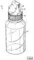
- Dropper bottle assembly 50 comprises a molded plastic bottle 52 designed to hold a liquid to be dispensed, for example, reagents used in laboratories and research facilities.
- Bottle 52 may take any desired configuration as is typical for such bottles. It is to be understood that any desired liquid to be dispensed may be placed within the bottle 52.
- Bottle 52 includes a neck portion 54 having external threads 56 and an outer rim 58 which defines an outlet 60 of the bottle 52.
- the bottle 52 is made of a low density polyethylene, however, the bottle 52 may be made out of any suitable plastic material. It is only necessary that the material of which the bottle is made be such that the sidewall 62 of bottle 52 is capable of being deflected so as to cause liquid to be dispensed therefrom.
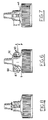
- the assembly 50 includes a molded plastic dispensing nozzle 64 (see Figures 3, 6, 7, 8 and 10) designed to engage neck portion 54 of bottle 52.
- nozzle 64 is made of a high density polyethylene plastic, however, nozzle 64 may be made of any other suitable plastic material desired.
- Nozzle 64 includes an annular skirt 66 having internal threads 68 which are designed to engage the external threads 56 of neck portion 54.
- An annular sealing ring 69 is disposed within annular skirt 66 which extends from top wall 71 of skirt 66 and is spaced from the internal surface 73 so to provide an annular recess 75 to receive the rim 58 of bottle 52.
- the sealing ring 69 is sized, shaped and spaced from internal surface 73 so as to provide a seal between nozzle 50 and bottle 52.
- the plastic dispensing nozzle 64 further includes a dispensing section 70 which is in fluid communication with the outlet 60 of bottle 52.
- Nozzle section 70 includes a dispensing passageway 72 for allowing a liquid within bottle 52 to pass out of nozzle 64.
- passageway 72 includes an axially inner section 74 having a substantially straight cylindrical opening having a diameter D of about .010 inches (.0254 cm) and an axially outer section 76.
- the outer section 76 starts with a diameter D adjacent the inner section 74 and increases as it approaches the outer dispensing end 78 of passageway 72.
- the outer section 76 has a substantially conical configuration.
- the present invention is not so limited.
- the dropper bottle assembly 50 includes a molded plastic closure cap 80 (which is best seen in Figures 3, 4, 5, 9 and 11) which is mounted on plastic nozzle 64 to be rotatable about a fixed point.
- the cap 80 is rotatably mounted to plastic nozzle 64 by a pair of axially aligned substantially cylindrically shaped projections 86 molded in cap 80 which rotate in circular opening 87 formed in a substantially C-shaped retaining member 88 which is integrally molded as a part of nozzle 64.
- the member 88 is designed to be substantially rigid so as to resist any substantial deformation that may result from the cap 80 being placed in the closed position.
- Member 88 has a width W, thickness t, and a configuration designed so that it can be integrally molded as part of nozzle 64.
- the opening 87 in member 88 is preferably slightly smaller than projection 86 so as to provide a friction fit which will permit the cap 80 to be positioned at any point along its path of rotation.
- alternative locking means may be provided to maintain the cap in the open dispensing position as illustrated in Figure 10, for example, through the use of indexing projections (not shown) between cap 80 and nozzle 50. This would allow positive positioning of cap in any position along its path of rotation.
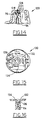
- Figure 9 illustrates the cap 80 in the closed (locked) position whereas Figure 10 illustrates the cap 80 in the open (dispensing) position.
- the cap 80 is a separate integrally molded part.
- the configuration of projections 86 and retaining member 88 allows easy installation of cap 80 to nozzle 64.
- the flexibility of projections 86 and member 88 allows cap 80 to be mounted to nozzle 64 by simply pushing cap 80 on nozzle 64 so as to snap projections 86 into opening 87. Therefore the cap 80 is easily captured on to nozzle 64, avoiding the necessity of completely removing cap 80 and preventing contamination thereof. This also allows easy use of the bottle during dispensing.
- the dispenser bottle assembly 50 includes locking means for securing said closure cap 80 on plastic nozzle 64 in the closed position.
- the locking means comprises a plurality of vertically aligned locking teeth 90 disposed on the outer surface of projection 92 which is integrally formed in nozzle 64.
- the projection 92 has a height h and width W1 which allows it to be integrally molded as a part of nozzle 64.
- the teeth 90 in the particular embodiment illustrated, have a pitch P of about .025 inches (.0635 cm), however, pitch P may be selected to any desired increment.
- the teeth 90 are oriented in a substantially horizontal direction as illustrated in Figure 7.
- Cap locking means further includes a flexible indexing finger 94 which is designed to engage teeth 90.
- Indexing finger 94 is preferably integrally formed with cap 80 as illustrated, and comprises a first substantially vertical section 95 which extends from the lower rim 97 of cap 80 and a substantially radially extending section 99 directed toward the center of cap 80.
- cap 80 has an opening 101 (see Figure 4) formed therein which substantially surrounds finger 94. It is important that cap 80 be made of an appropriate plastic material to allow flexibility and durability of cap 80 and finger 94 so as to allow repeated flexure without damage to finger 94 or taking a permanent set. Applicants have found that polycarbonate or acetal will provide the desired performance.
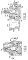
- the cap 80 is rotated to the position illustrated in Figure 9 which causes the inner end 102 of radially extended section 99 of index finger 94 to slide down over teeth 90 and seat into one of the appropriate spaces provided between teeth 90. Thereafter the cap 80 is released and held in position by the indexing finger 94 engaging the adjacent tooth.
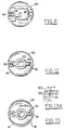
- a substantially axial force is applied to cap 80 as indicated by arrow 98 in Figures 13 and 13A to cause the cap 80 to flex a sufficient amount so as to cause indexing finger 94 to axially slide past the side 100 of teeth 90. This will disengage the indexing finger 94 from the locking teeth 90. Since a sliding action is used to disengage the index finger 94, the force required is substantially dependant upon the resistance to the axial movement and is relatively independent of the amount of locking force being applied to the finger 94 in the vertical direction. Indexing finger 94 is designed such that when in the normal unengaged position, its inner end 102 extends radially inward of the bottom of teeth 90 (see Figure 13a).
- the bottle assembly 50 is further provided with means for sealing the outer dispensing end 78 of passageway 72.
- this is accomplished by providing a projection 96 within the interior of the cap 80 and positioned such that it will engage the outer dispensing end 78 of passageway 72.
- the projection 96 is substantially hemispherical or dome shaped such that it will engage the substantially conical surface provided in the outer section 76 of passageway 72 so as to provide an annular seal therebetween. It can be seen as the cap 80 is rotated in the locked position the projection 96 engages the outer dispensing end to form a sealing engagement therewith.
- the cap 80 is made of a flexible plastic material so as to provide substantially constant force against the outer surface of the outer section 76 when the cap is in the locked position. Typically a sealing force of about 10 pounds is applied when the cap 80 is in the locked position.
- FIG. 14 there is illustrated a partial cross sectional view of a modified cap 120 made in accordance with the present invention.
- the cap 120 is provided with an alternative sealing means for engaging axially outer section 76 of nozzle 64.
- a flexible projection 122 is provided which is made of an appropriate elastomeric or rubber material which is capable of greater deformation (as opposed to the relatively harder rigid plastic material of the cap or nozzle) so as to better conform to and seal with outer section 76.
- the projection includes an elongated retainer section 128 which is press fit into an opening 124 in cap 120.
- the outer end 126 is substantially bulbous shaped so as to assist in retaining projection 122 onto cap 120.
- the projection may be secured to cap in any desired manner, for example by the use of an adhesive or other mechanical locking arrangement.
- FIG. 15 and 16 there is illustrated yet another modified cap 130 made in accordance with the present invention.
- a flexible projection 136 is molded in cap 130.
- An opening 134 extends around projection a distance so as to form a flexible connecting portion 132.
- opening 134 extends about 300° around projection 136.
- FIG. 17-20 there is illustrated a modified nozzle and cap assembly made in accordance with the present invention, like numerals referring to identical parts, previously discussed.
- a nozzle 164 which is designed to engage the neck portion 54 of bottle 52 in the same manner as nozzle 64.
- the locking means for securing cap 180 to nozzle 164 operates in the same general manner as that illustrated in Figures 9-13 except that a greater number of locking positions are provided.
- a pair of spaced projections 150, 151 are molded on the exterior of nozzle 164.
- Each projection 151, 151 has a plurality of teeth 154 having a pitch P.
- the teeth 154 of projection 150 are disposed approximately midway between the teeth 154 of projection 151 as illustrated in Figures 19 and 20. In the particular embodiment illustrated, teeth 154 of projection 150 are staggered with respect to teeth 151 of projection 156 by a distance h which is about one half of pitch P.
- Cap 80 includes a pair of independent indexing fingers 160, 161 which are designed to engage teeth 154 of projections 150, 151, respectively, in the same manner as indexing finger 94 engages teeth 90.
- Cap 180 is secured to nozzle 164 in the same manner as cap 80 is secured to nozzle 64.
- the cap 180 in the closed position is rotated to the position illustrated in Figure 20.
- Indexing fingers 160, 161 slide over teeth 154 of projection 150, 151, respectively. How far the cap can be pushed down will determine which indexing finger 160 or 161 will engage teeth 154 so as to secure the cap 180 in the locked position.
- the size and pitch of the teeth can remain sufficiently large so as to provide a secure engagement between the indexing finger and adjacent tooth.
- indexing finger 160 or 161 will provide the locking means while the other indexing finger will slide down on the adjacent tooth as illustrated by dash lines in Figure 20.
- the cap 180 is disengaged from nozzle 164 in the same general manner as cap 80 is disengaged with nozzle 64.
- the cap 180 is deformed so that indexing finger 160 and 161 slide past the side 170 of the projection 150, 151.
- the indexing fingers 160, 161 will go forward toward nozzle 164 in the same manner as indexing finger 94 so as to prevent re-engagement with the adjacent teeth.
- the space D between projections 150, 151 is greater than the width W of indexing fingers 160, 161 so that they can easily disengage the adjacent tooth 154.
- cap 180 is separated between indexing finger 160, 161 so as to allow free independent movement.
- Nozzle 264 is similar to nozzle 64, like numerals indicating like parts, except that the dispensing section 70 has been slightly modified.
- the outer tip 270 adjacent outlet 272 has been configured so as to provide greater compliance to provide better sealing relationship with projection 96 in cap 80 when the cap 80 is placed in the closed position.
- Dispensing passageway 76 comprises four (4) discrete sections which assist in accurately controlling of the dispensing of individual drops.
- Passageway 76 has an inner section 280 having a diameter D1, and length L1.
- L1 is about .010 inches (.254 cm) and D1, is about .010 inches (.254 cm).
- Adjacent inner section 280 is a first conical transition section 282 which increases to a diameter D2 and has a length L2. In the embodiment illustrated diameter D2 is .047 inches (.119cm) and L2 is about .032 inches (.0813cm).
- a fourth outer section 286 is disposed adjacent second conical section 284 to form outlet 272 having a diameter D4.
- D3 is about .060 inches (.152cm)
- L3 is about .184 inches (.467cm)
- D4 is about .110 inches (.279 cm)
- L4 is about .043 inches (.109cm).
- Fourth outer section 286 has an conical surface 288 which forms an angle ⁇ with respect to the longitudinal axis X-X of passageway 76.
- ⁇ is about 30 degrees.
- ⁇ may be varied as desired. Preferably it is no more than about 45 degrees.
- Tip 270 adjacent outlet 272 has a thickness T1.
- the tip 270 has an outer surface 290 disposed at an angle ⁇ so that tip 270 increases to a thickness T2 at a length L5.
- T1 is about .005 inches (.0127 cm)
- T2 is about .042 inches (.1067 cm)
- L5 is about .030 inches (.0762 cm).
- the values for T1, T2, and L3 are selected such that tip 270 is sufficiently compliant so as to conform to projection 96 in cap 80 so as to assist in providing a liquid tight seal there between.
- the material selection will of course also affect the selection of T1, T2, and L3 to obtain the desired compliance.
- nozzle 264 is made of a high density polyethylene.
- T3 The thickness of nozzle 264 goes to T3 at the lower end of tip 270 so as to provide the desired rigidity for the remaining portion of nozzle 264.
- T3 is about .049 inches (.229 cm), however, T3 may be varied as desired to provide the degree of rigidity desired.
- the flexible indexing finger may be molded in the nozzle and the corresponding teeth may be formed on the internal surface of the cap.
Landscapes
- Engineering & Computer Science (AREA)
- Mechanical Engineering (AREA)
- Closures For Containers (AREA)
Claims (13)
- Tröpfelflaschenanordnung (50) mit einer Kunststoffflasche (52), einer Kunststoffportionierdüse (64;164;264) mit einem angebrachten Überwurf (66) zur Befestigung an der Flasche, wobei die Portionierdüse einen verlängerten Portionierabschnitt (70) besitzt der sich von dem Überwurf zu einem entfernten offenen Ende (78;272) erstreckt und mit einer Kunststoffkappe (80;120;180) mit einer Ausnehmung, wobei die Kappe und die Düse zusammenwirkende Mittel (86,86,88) zur schwenkbaren Befestigung der Kappe an der Düse aufweisen und wobei die Kappe schwenkbar ist zwischen einer geschlossenen Stellung bei der der Portionierabschnitt innerhalb der Kappenausnehmung ist und einer offenen Stellung, bei welcher das offene Ende des Portionierabschnitts zugänglich ist und mit ersten Verschlußmitteln (94,95;160,161) an der Kappe und mit zweiten Verschlußmitteln (90,92;150,151) an der Düse, wobei die ersten und zweiten Verschlußmittel zusammenwirken um die schwenkbar befestigte Kappe in der geschlossenen Position zu sichern, eines der Verschlußmittel weist eine Verzahnungsvorrichtung auf und das andere der Verschlußmittel Finger, Verzahnungsvorrichtung und Finger arbeiten verschließend miteinander sobald die Kappe von der offenen zur geschlossenen Position verschwenkt wird, sowie mit Dichtungsmitteln (96;122;136) an der Kappe zum Verschluß des offenen Endes des Portionierabschnitts in geschlossener Position der Kappe, dadurch gekennzeichnet, daß die Kappe getrennt von der Portionierdüse gebildet ist, daß die durch die Kappe gebildete Ausnehmung zur Aufnahme des Portionierabschnitts bemessen ist, daß die zweiten Verschlußmittel an dem Portionierabschnitt der Düse mit Abstand von dem offenen Ende des Portionierabschnitts sitzen, daß die Verzahnungsmittel aus einer Mehrzahl von im wesentlichen unnachgiebigen Zähnen (90;150,151) bestehen, die wenigstens eine Reihe bilden und daß der Finger elastisch hervorsteht (94;160,161).
- Tröpfelflaschenanordnung nach Anspruch 1, dadurch gekennzeichnet, daß die Dichtungsmittel von einer inneren Oberfläche (96;122;136) der Kappe gebildet werden, die in der geschlossenen Position der Kappe dichtungsartig mit dem offenen Ende (78) des Portionierabschnitts zusammenwirkt.
- Tröpfelflaschenanordnung nach Anspruch 1 oder 2, dadurch gekennzeichnet, daß die Dichtungsmittel einen von der Kappe herunterhängenden Vorsprung (96;122;136) beinhalten, der in der geschlossenen Position der Kappe in die Ausnehmung zum dichtungsartigen Zusammenwirken mit dem offenen Ende (78) des Portionierabschnittes hervorsteht.
- Tröpfelflaschenanordnung nach Anspruch 3, dadurch gekennzeichnet, daß um einen Bereich des Vorsprungs (136) eine Öffnung (134) in der Kappe vorgesehen ist, wodurch dieser biegsam wird.
- Tröpfelflaschenanordnung nach einem der vorangegangenen Ansprüche, dadurch gekennzeichnet, daß die Mittel zur schwenkbaren Befestigung der Kappe an der Düse wenigstens einen zylindrischen Vorsprung (86) und ein vorspringendes Aufnahmeteil (88) beinhalten, angeformt an der Düse beziehungsweise der Kappe, wobei der zylindrische Vorsprung von einer Öffnung (87) in den Aufnahmeteil aufgenommen wird.
- Tröpfelflaschenanordnung nach einem der vorangegangenen Ansprüche, dadurch gekennzeichnet, daß die Mittel zur schwenkbaren Befestigung der Kappe (80) an der Düse (64;164;264) wenigstens teilweise an der Düse angebracht sind, beabstandet von dem Düsenüberwurf (66), wobei die zweiten Verschlußmittel ebenfalls beabstandet von dem Düsenüberwurf sind.
- Tröpfelflaschenanordnung nach einem der vorangegangenen Ansprüche, dadurch gekennzeichnet, daß die Flasche einen äußeren gewindeartigen Flaschenhalsbereich (54) und daß der Düsenüberwurf (66) ringförmig ein Innengewinde (68) zum Zusammenwirken mit dem Außengewinde (56) des Flaschenhalsbereichs aufweist.
- Tröpfelflaschenanordnung nach einem der vorangegangenen Ansprüche, dadurch gekennzeichnet, daß die Kappe axial deformierbar zum Lösen von Finger und Verzahnungsvorrichtung ist.
- Tröpfelflaschenanordnung nach einem der vorangegangenen Ansprüche, dadurch gekennzeichnet, daß die Zähne in wenigstens einer Reihe (90) auf der Düse im wesentlichen parallel zum Portionierabschnitt und der vorstehende Finger (94) an der Kappe angeformt sind.
- Tröpfelflaschenanordnung nach Anspruch 9, dadurch gekennzeichnet, daß die Zähne in zwei Reihen (154) allgemein parallel zum Portionierabschnitt angeformt sind und der vorstehende Finger (160) mit einer ersten Reihe der Zähne zusammenwirkt, wobei an der Kappe ein zweiter vorstehender Finger (161) angeformt und so positioniert ist, daß er mit der zweiten Reihe der Zähne zusammenwirkt.
- Tröpfelflaschenanordnung nach Anspruch 10, dadurch gekennzeichnet, daß die Zähne der ersten Reihe (154) bezüglich der Zähne der zweiten Reihe (154) zur Erzielung unterschiedlicher Verschlußstellungen von Reihe zu Reihe versetzt sind.
- Tröpfelflaschenanordnung nach einem der vorangegangenen Ansprüche, dadurch gekennzeichnet, daß die Mittel zur schwenkbaren Befestigung der Kappe an der Flasche eine ortsfeste Schwenkachse definieren, um welche die Kappe zwischen offener und geschlossener Stellung verschwenkbar ist.
- Tröpfelflaschenanordnung nach einem der vorangegangenen Ansprüche, dadurch gekennzeichnet, daß eines der ersten und zweiten Verschlußmittel nachgiebig ist.
Applications Claiming Priority (2)
| Application Number | Priority Date | Filing Date | Title |
|---|---|---|---|
| US51846590A | 1990-05-03 | 1990-05-03 | |
| US518465 | 1990-05-03 |
Publications (3)
| Publication Number | Publication Date |
|---|---|
| EP0455916A2 EP0455916A2 (de) | 1991-11-13 |
| EP0455916A3 EP0455916A3 (en) | 1992-12-02 |
| EP0455916B1 true EP0455916B1 (de) | 1996-02-07 |
Family
ID=24064053
Family Applications (1)
| Application Number | Title | Priority Date | Filing Date |
|---|---|---|---|
| EP19900314446 Expired - Lifetime EP0455916B1 (de) | 1990-05-03 | 1990-12-31 | Flasche mit Tropfvorrichtung |
Country Status (4)
| Country | Link |
|---|---|
| EP (1) | EP0455916B1 (de) |
| JP (1) | JPH0790870B2 (de) |
| CA (1) | CA2041675A1 (de) |
| DE (1) | DE69025320T2 (de) |
Cited By (4)
| Publication number | Priority date | Publication date | Assignee | Title |
|---|---|---|---|---|
| US7114403B2 (en) | 2003-05-30 | 2006-10-03 | Oakville Hong Kong Co., Ltd | Fluid collection and application device and methods of use of same |
| US7544324B2 (en) | 2003-11-14 | 2009-06-09 | Oakville Hong Kong Company Limited | Rapid sample analysis storage devices and methods of use |
| US8071394B2 (en) | 2006-07-26 | 2011-12-06 | Alere Switzerland Gmbh | Test device for detecting an analyte in a liquid sample |
| US8871155B2 (en) | 2005-11-30 | 2014-10-28 | Alere Switzerland Gmbh | Devices for detecting analytes in fluid sample |
Families Citing this family (10)
| Publication number | Priority date | Publication date | Assignee | Title |
|---|---|---|---|---|
| US5328058A (en) * | 1990-05-03 | 1994-07-12 | Nalge Company | Dropper bottle assembly with squeeze cap |
| ATE237474T1 (de) | 1991-01-18 | 2003-05-15 | Canon Kk | Tintenstrahlaufzeichnungsverfahren und - vorrichtung mit thermischer energie |
| US5358151A (en) * | 1993-05-21 | 1994-10-25 | Universal Container Corporation | Liquid dropper dispenser |
| IT246042Y1 (it) * | 1998-05-14 | 2002-03-26 | Lameplast Srl | Ugello per la erogazione di liquidi in gocce |
| WO2001012124A1 (en) * | 1999-08-17 | 2001-02-22 | Santen Pharmaceutical Co., Ltd. | Open instillation container and method of manufacturing the container |
| JP2002362603A (ja) * | 2001-06-06 | 2002-12-18 | Kitano Seisaku Kk | 目薬用容器 |
| JP4796307B2 (ja) * | 2005-02-03 | 2011-10-19 | 大成化工株式会社 | 滴下用のノズル孔構造、このノズル孔構造を有する滴下ノズル |
| GB2448725A (en) * | 2007-04-25 | 2008-10-29 | Rpc Containers Ltd | Dispensing closure having a nozzle |
| CA2721263C (en) * | 2008-04-24 | 2016-04-05 | Tomoyuki Shibata | Compound container and pouring-out method |
| CN105691869B (zh) * | 2016-03-09 | 2019-10-29 | 深圳瀚星翔科技有限公司 | 一次性烟油加注瓶 |
Family Cites Families (2)
| Publication number | Priority date | Publication date | Assignee | Title |
|---|---|---|---|---|
| DE8535205U1 (de) * | 1985-12-14 | 1986-02-06 | Vedder & Comp. GmbH, 5750 Menden | Verschluß |
| US4742928A (en) * | 1987-06-11 | 1988-05-10 | W. Braun Company | Dispensing closure with articulated flip-top cap |
-
1990
- 1990-12-31 DE DE1990625320 patent/DE69025320T2/de not_active Expired - Fee Related
- 1990-12-31 EP EP19900314446 patent/EP0455916B1/de not_active Expired - Lifetime
-
1991
- 1991-05-02 CA CA 2041675 patent/CA2041675A1/en not_active Abandoned
- 1991-05-02 JP JP10025991A patent/JPH0790870B2/ja not_active Expired - Fee Related
Cited By (5)
| Publication number | Priority date | Publication date | Assignee | Title |
|---|---|---|---|---|
| US7114403B2 (en) | 2003-05-30 | 2006-10-03 | Oakville Hong Kong Co., Ltd | Fluid collection and application device and methods of use of same |
| US7544324B2 (en) | 2003-11-14 | 2009-06-09 | Oakville Hong Kong Company Limited | Rapid sample analysis storage devices and methods of use |
| US7837939B2 (en) | 2003-11-14 | 2010-11-23 | Alere Switzerland Gmbh | Rapid sample collection and analysis device and methods of use |
| US8871155B2 (en) | 2005-11-30 | 2014-10-28 | Alere Switzerland Gmbh | Devices for detecting analytes in fluid sample |
| US8071394B2 (en) | 2006-07-26 | 2011-12-06 | Alere Switzerland Gmbh | Test device for detecting an analyte in a liquid sample |
Also Published As
| Publication number | Publication date |
|---|---|
| DE69025320T2 (de) | 1996-08-22 |
| EP0455916A3 (en) | 1992-12-02 |
| DE69025320D1 (de) | 1996-03-21 |
| CA2041675A1 (en) | 1991-11-04 |
| JPH0585556A (ja) | 1993-04-06 |
| EP0455916A2 (de) | 1991-11-13 |
| JPH0790870B2 (ja) | 1995-10-04 |
Similar Documents
| Publication | Publication Date | Title |
|---|---|---|
| US5246145A (en) | Liquid dropper spout having lockable pivoted closure cap | |
| EP0455916B1 (de) | Flasche mit Tropfvorrichtung | |
| US5328058A (en) | Dropper bottle assembly with squeeze cap | |
| US4632264A (en) | Plastic cap having a seal and being child-proof | |
| US5095962A (en) | Beverage dispenser coupling | |
| US5221017A (en) | Controlled dropper tip closure | |
| RU2094342C1 (ru) | Контейнер с крышкой | |
| EP0253495B1 (de) | Aufbewahrungsbehälter für Reinigungslösung von Kontaktlinsen | |
| US5096077A (en) | Stoppering device non-removably attached to the neck of a container | |
| US10252838B2 (en) | Drinking containers and related methods | |
| US5954233A (en) | Sealed container | |
| CN101952177B (zh) | 具有防止狭缝未对准的特征的阀安装组件 | |
| US4230112A (en) | Syringe-type liquid container dispenser adapter | |
| US5819984A (en) | Package with storage and plug retention features | |
| US20130160891A1 (en) | Pediatric dosing dispenser | |
| EP0598223B1 (de) | Spenderkappe für einen flüssige Substanzen enthaltenden Behälter mit einem beweglichen Ausgiesser | |
| AU1990892A (en) | Closure system for covered receptacles and the like | |
| CN113784897B (zh) | 儿科剂量分配器 | |
| IL160733A (en) | Transfer device, in particular for medical fluids | |
| US8499985B2 (en) | Automatic dispensing cap for squeezable bottle | |
| US20130193170A1 (en) | Dispensing cap for a squeezeable bottle | |
| EP0697982B1 (de) | Verschluss mit einer zweiteiligen verschiebbaren spenderkappe | |
| GB2106480A (en) | Valve and container for medical liquids | |
| US11230415B2 (en) | Container with cap structure | |
| US20060273061A1 (en) | Method and device for a child resistant dropper closure |
Legal Events
| Date | Code | Title | Description |
|---|---|---|---|
| PUAI | Public reference made under article 153(3) epc to a published international application that has entered the european phase |
Free format text: ORIGINAL CODE: 0009012 |
|
| AK | Designated contracting states |
Kind code of ref document: A2 Designated state(s): CH DE FR GB IT LI |
|
| PUAL | Search report despatched |
Free format text: ORIGINAL CODE: 0009013 |
|
| AK | Designated contracting states |
Kind code of ref document: A3 Designated state(s): CH DE FR GB IT LI |
|
| 17P | Request for examination filed |
Effective date: 19930324 |
|
| 17Q | First examination report despatched |
Effective date: 19940317 |
|
| GRAA | (expected) grant |
Free format text: ORIGINAL CODE: 0009210 |
|
| AK | Designated contracting states |
Kind code of ref document: B1 Designated state(s): CH DE FR GB IT LI |
|
| PG25 | Lapsed in a contracting state [announced via postgrant information from national office to epo] |
Ref country code: IT Free format text: LAPSE BECAUSE OF FAILURE TO SUBMIT A TRANSLATION OF THE DESCRIPTION OR TO PAY THE FEE WITHIN THE PRESCRIBED TIME-LIMIT;WARNING: LAPSES OF ITALIAN PATENTS WITH EFFECTIVE DATE BEFORE 2007 MAY HAVE OCCURRED AT ANY TIME BEFORE 2007. THE CORRECT EFFECTIVE DATE MAY BE DIFFERENT FROM THE ONE RECORDED. Effective date: 19960207 |
|
| REF | Corresponds to: |
Ref document number: 69025320 Country of ref document: DE Date of ref document: 19960321 |
|
| ET | Fr: translation filed | ||
| PLBE | No opposition filed within time limit |
Free format text: ORIGINAL CODE: 0009261 |
|
| STAA | Information on the status of an ep patent application or granted ep patent |
Free format text: STATUS: NO OPPOSITION FILED WITHIN TIME LIMIT |
|
| 26N | No opposition filed | ||
| PGFP | Annual fee paid to national office [announced via postgrant information from national office to epo] |
Ref country code: FR Payment date: 19971209 Year of fee payment: 8 |
|
| PGFP | Annual fee paid to national office [announced via postgrant information from national office to epo] |
Ref country code: CH Payment date: 19980109 Year of fee payment: 8 |
|
| PGFP | Annual fee paid to national office [announced via postgrant information from national office to epo] |
Ref country code: DE Payment date: 19980112 Year of fee payment: 8 |
|
| PG25 | Lapsed in a contracting state [announced via postgrant information from national office to epo] |
Ref country code: LI Free format text: LAPSE BECAUSE OF NON-PAYMENT OF DUE FEES Effective date: 19981231 Ref country code: CH Free format text: LAPSE BECAUSE OF NON-PAYMENT OF DUE FEES Effective date: 19981231 |
|
| REG | Reference to a national code |
Ref country code: CH Ref legal event code: PL |
|
| PG25 | Lapsed in a contracting state [announced via postgrant information from national office to epo] |
Ref country code: FR Free format text: LAPSE BECAUSE OF NON-PAYMENT OF DUE FEES Effective date: 19990831 |
|
| REG | Reference to a national code |
Ref country code: FR Ref legal event code: ST |
|
| PG25 | Lapsed in a contracting state [announced via postgrant information from national office to epo] |
Ref country code: DE Free format text: LAPSE BECAUSE OF NON-PAYMENT OF DUE FEES Effective date: 19991001 |
|
| REG | Reference to a national code |
Ref country code: GB Ref legal event code: IF02 |
|
| PGFP | Annual fee paid to national office [announced via postgrant information from national office to epo] |
Ref country code: GB Payment date: 20091230 Year of fee payment: 20 |
|
| REG | Reference to a national code |
Ref country code: GB Ref legal event code: PE20 Expiry date: 20101230 |
|
| PG25 | Lapsed in a contracting state [announced via postgrant information from national office to epo] |
Ref country code: GB Free format text: LAPSE BECAUSE OF EXPIRATION OF PROTECTION Effective date: 20101230 |