EP0455953A1 - Store avec articulation flexible - Google Patents
Store avec articulation flexible Download PDFInfo
- Publication number
- EP0455953A1 EP0455953A1 EP91103635A EP91103635A EP0455953A1 EP 0455953 A1 EP0455953 A1 EP 0455953A1 EP 91103635 A EP91103635 A EP 91103635A EP 91103635 A EP91103635 A EP 91103635A EP 0455953 A1 EP0455953 A1 EP 0455953A1
- Authority
- EP
- European Patent Office
- Prior art keywords
- awning
- bearing
- spiral spring
- pivot bearing
- drop
- Prior art date
- Legal status (The legal status is an assumption and is not a legal conclusion. Google has not performed a legal analysis and makes no representation as to the accuracy of the status listed.)
- Granted
Links
- 239000004744 fabric Substances 0.000 claims abstract description 16
- 238000004804 winding Methods 0.000 claims description 8
- 238000010276 construction Methods 0.000 description 2
- 230000005540 biological transmission Effects 0.000 description 1
- 230000000694 effects Effects 0.000 description 1
- 230000005484 gravity Effects 0.000 description 1
- 230000037431 insertion Effects 0.000 description 1
- 238000003780 insertion Methods 0.000 description 1
- 239000000463 material Substances 0.000 description 1
- 230000036316 preload Effects 0.000 description 1
- 230000000717 retained effect Effects 0.000 description 1
Images

Classifications
-
- E—FIXED CONSTRUCTIONS
- E06—DOORS, WINDOWS, SHUTTERS, OR ROLLER BLINDS IN GENERAL; LADDERS
- E06B—FIXED OR MOVABLE CLOSURES FOR OPENINGS IN BUILDINGS, VEHICLES, FENCES OR LIKE ENCLOSURES IN GENERAL, e.g. DOORS, WINDOWS, BLINDS, GATES
- E06B9/00—Screening or protective devices for wall or similar openings, with or without operating or securing mechanisms; Closures of similar construction
- E06B9/56—Operating, guiding or securing devices or arrangements for roll-type closures; Spring drums; Tape drums; Counterweighting arrangements therefor
- E06B9/92—Means allowing the closures to be shifted out of the plane of the opening
-
- E—FIXED CONSTRUCTIONS
- E06—DOORS, WINDOWS, SHUTTERS, OR ROLLER BLINDS IN GENERAL; LADDERS
- E06B—FIXED OR MOVABLE CLOSURES FOR OPENINGS IN BUILDINGS, VEHICLES, FENCES OR LIKE ENCLOSURES IN GENERAL, e.g. DOORS, WINDOWS, BLINDS, GATES
- E06B9/00—Screening or protective devices for wall or similar openings, with or without operating or securing mechanisms; Closures of similar construction
- E06B9/56—Operating, guiding or securing devices or arrangements for roll-type closures; Spring drums; Tape drums; Counterweighting arrangements therefor
- E06B9/68—Operating devices or mechanisms, e.g. with electric drive
Definitions
- the invention relates to an awning with the features of the preamble of claim 1.
- a generic Markisolette which contains two vertical guide rails running parallel and at a distance from each other below the winding shaft, which are to be attached on both sides next to the window of a building.
- Two guide slides run on the two guide rails, which are connected to each other at their upper end via a rotatably mounted deflection roller for the awning fabric.
- Each of the sledges carries on his lower end a hinge joint for a drop arm, which is biased towards the unfolded position by means of a spiral spring.
- the free ends of the two extension arms are also connected to each other by the extension rod to which the free end of the awning cover is attached.
- the aim is to ensure that when the awning cover is extended following the maximum possible downward stroke of the guide slides, the extension arms begin to swing out so that the awning cover, which runs under the deflection roller, is tilted outwards away from the window.
- the hinge joints for the extension arms consist of a bearing journal fastened to the guide slide, on which the respective extension arm is pivotably seated with a corresponding bore.
- the spiral spring is arranged next to it and does not take on any radial forces, because these are only transmitted from the hole in the extension arm to the bearing journal. This construction is very widespread in practice, but takes up considerable space in the lateral direction because the spring sits next to the hinge joint. The arrangement looks too bulky when it comes to marqueisolettes on small room windows.
- a particularly good lateral guidance can be achieved if the spiral spring is designed as a band spiral spring, as a result of which larger forces can be transmitted in the lateral direction, that is to say parallel to the drop rod.
- the mounting and mounting of the coil spring does not require any clamping devices if the pin on which the coil spring is seated is provided with an opening for receiving the corresponding end.
- this opening is a slot open to one end of the bearing journal, which ensures that the coil spring is easily attached.
- connection of the spiral spring to the extension arm is also very simple if the outer end of the spiral spring is angled so that it protrudes radially outward and this end is inserted into a corresponding opening of the extension arm.
- a simple self-locking shaft locking ring which is pushed onto the bearing journal, is sufficient.
- This can optionally be integrally connected to a cap to complete the free end of the journal.
- the awning according to the invention can be designed both as a drop arm awning and as an awning isolet.
- the swivel bearing of each extension arm is stationary next to the window to be shaded, while in the case of the marquise there are two guide rails next to the window on which the guide slides run, which in turn carry the swivel bearings for the extension arms.
- the filigree impression of the new swivel bearing is retained if the stop provided at the lower end of the movement stroke of the guide carriage is provided with a wire eyelet which interacts with the bracket provided on the extension arm.
- This bracket together with the eyelet, has the task of ensuring that when the awning cover is retracted, the extension arms are first folded against the action of the spiral springs on the guide carriage before the guide carriage moves upwards when the awning cover is retracted further.
- This bracket does not have to take on excessive forces and can therefore be designed as a wire bracket, which in any case has the shape of an arc that is concentric with the center of the coil spring.
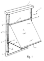
- an awning isolate 1 is illustrated, which is attached in front of a window 2 of a building, not shown, and in a box 3 open at the bottom contains a winding shaft, not further visible, onto which an awning cloth 4 can be wound, with its rear edge on the winding shaft is attached.
- a winding shaft not further visible
- the two guide rails 5 and 6 are held at their lower end adjacent to the lower edge of the window 2 by wall brackets 7, while the upper end is connected to the box 3.
- the two guide rails 5 and 6 are used for the displaceable mounting of two mutually identical but mutually mirror-image guide carriages 8, at the upper end of which a deflection roller 9 is rotatably mounted, which extends between the two guide carriages 8.
- the lower end of each of the two guide carriages 8 carries a pivot bearing 11, via which a drop arm 12 is pivotally connected to the associated guide carriage 8.
- the pivot axes of the two pivot bearings 11 are at the same height and are aligned with one another, i.e. they lie on a common straight line which is parallel to the axis of the winding shaft or the deflection roller 9.
- a drop rod 13 is connected to which the front edge of the awning fabric 4 is anchored.
- the Markisolette 1 in Fig. 1 is shown in a partially extended position, in which the two guide carriages 8 their lowest position on the Have reached guide rails 5, 6 and the two parallel extending arms 12 are pivoted out of the window 2 protruding.
- the awning cloth 4 therefore runs approximately vertically between the box 3 and the deflecting roller 9 and starting from the deflecting roller 9 up to the drop bar 13 obliquely downward from the window 2.
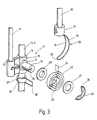
- the pivot bearing 11 of the guide carriage 8, which runs on the guide rail 5, is shown in detail in FIGS. 2 and 3.
- the pivot bearing 11 of the other guide carriage 8, which is guided on the guide rail 6 so as to be longitudinally displaceable, is mirror-symmetrical, so that the description given below also applies to the other pivot bearing.
- the guide carriage 8 has at its lower end a sleeve 16 provided with two parallel through bores 14 and 15, which is tapered in a web-like manner between the two bores 14 and 15.
- the guide rail 5 runs through the bore 14 with little play, so that the sleeve 16 can easily be pushed back and forth on the guide rail 5.
- a cylindrical strut 17 is clamped in the bore 15 and leads to an upper guide sleeve 18, on which the deflection roller 9 is rotatably mounted.
- the guide sleeve 18 can be easily pushed back and forth on the guide rail 5 with little play.
- the distance between the sleeves 16 and 18 is slightly larger than the extension arms 12 are long.
- the guide sleeve 16 carries a cylindrical bearing pin 19, the longitudinal axis of which is perpendicular to a plane which contains the longitudinal axes of the two bores 14 and 15.
- the bearing pin 19 protrudes on one side and goes on the sleeve 16 adjacent to it End in a flat annular shoulder 21. It serves as a seat for a coil spring 22, the inner end 23 of which is bent radially inward and the outer end 24 projecting radially outward. With the inner section 23, the spiral spring 22 engages in a longitudinal slot 25 of the bearing pin 19.
- the longitudinal slot 25 is open towards the free end of the bearing pin 19 and points in the direction of the bore 15.
- the width of the slot 25 corresponds to the material thickness of the spiral spring 22 , which has about three to four courses.
- a washer 26 is arranged between the annular shoulder 21 and the spiral spring 22 and there is also a further washer 27 on the side of the spiral spring 22 remote from the sleeve 16, which has the same dimensions as the washer 26.
- the axial securing of the washers 26 and 27 as well as the spiral spring 22 on the bearing journal 19 is carried out by a securing element 28, which is designed in the manner of a self-locking locking washer, which integrally molded with a dome-shaped cap 29.
- the extension arm 12 is placed on the section 24 of the spiral spring 22 with a corresponding slot.
- the slot is not shown in the figures; instead, section 24 is illustrated in dashed lines in FIG. 2.
- the slot is pressed together after the insertion of the section 24 in order to establish a frictional connection between the section 24 and the extension arm 12.
- a wire bracket 32 which has two mutually parallel legs 33 and 34, which are integrally connected to one another at their end remote from the extension arm 12 at 35.
- the wire bracket 32 has the course of a circular arc which, when the pivot bearing 11 is mounted, as can be seen in FIG. 2, is concentric with the axis of the bearing pin 19.
- the deepest point that the guide carriage 8 can reach on the respective guide rail 5, 6 is defined by an adjusting ring 36, which is clamped by means of a clamping screw 37 at the corresponding point on the guide rail 5 or 6.
- the guide slide 8 with the coil spring 22 strikes a wire eyelet 38 of the adjusting ring 36, as a result of which further downward movement is limited.
- the wire eyelet 38 stands radially away from the guide rail 5 or 6 and its distance from the bearing pin 39 is dimensioned such that when the coil spring 22 stands on the eyelet 38, it is the same size as the radius of curvature of the bracket 32.
- the eyelet 38 lies parallel to the trunnion.
- the awning 1 described so far works in the following way: If it is initially assumed that the awning 1 is completely retracted, the two extension arms 12 are pivoted vertically upwards, the extension rod 13 running just below the deflection roller 9. In addition, the sleeves 18 of the two guide carriages 8 rest against the upper fastening of the two guide rails 5, 6.
- the two guide carriages 8 first run on the guide rails 5 and 6 down until the sleeve 16 located at the bottom of the guide carriage 8 stands on the respective associated adjusting ring 36.
- the two adjusting rings 36 are mounted on the two guide rails 5 and 6 at the same height.
- the extension arms 12 are pivoted outwards away from the wall due to the return force of the coil spring 22.
- the wire bracket 32 enters the wire eyelet 38.
- the awning fabric 4 which occurs under the deflection roller 9, is held taut by the effect of the weight of the extension rod, 13 of the two extension arms 12 and the torque generated by the two coil springs 22, so that the in FIG. 1 recognizable position comes about.
- the extension arms 12 pivot more or less far down.
- the awning fabric 4 is in turn wound onto the winding shaft, as a result of which a force is generated which tends to pull the guide carriages 8 on the guide rails 5 and 6 upwards.
- the guide carriages 8 are prevented from this upward movement by the two brackets 32 which are inserted in the wire eyelets 38.
- the extension arms 12 are therefore first pivoted upward against the force of gravity and against the torque exerted by the spiral springs 22. Only when the drop arms 12 are almost completely pivoted upwards come on both sides of the wire bracket 32 free from the wire eyelets 38 so that the awning cloth 4 can lift the guide carriage 8.
- the now more preloaded coil springs 22 exert a greater torque on the drop arms 12, the weight of the guide carriage 8 together with the drop arms 12, the drop rod 13 and the deflection roller 9 is sufficient to counter the action of the drop arms 12 in the vertical direction 22 Hold position.
- the extension arms 12 in the awning 1 are connected to the associated guide carriages 8 exclusively via the spiral spring 22.
- the spiral spring 22 therefore also takes over the transmission of the transverse or tensile forces to or from the respective extension arm 12.
- the washers 26 and 27 are used only to improve the lateral guidance of the coil springs 22 and they are intended to prevent foreign bodies from entering between the layers of the coil springs 22.
- the extension arms 12 are given an additional moment by the coil springs 22 even in the fully pivoted-out state.
- the position of the coil spring 22 shown in FIG. 3 is not the relaxed state, but rather the state belonging to the corresponding position of the drop arm 12, in which the coil spring 22 is preloaded.
Landscapes
- Engineering & Computer Science (AREA)
- Structural Engineering (AREA)
- Architecture (AREA)
- Civil Engineering (AREA)
- Building Awnings And Sunshades (AREA)
- Operating, Guiding And Securing Of Roll- Type Closing Members (AREA)
- Tents Or Canopies (AREA)
Priority Applications (1)
| Application Number | Priority Date | Filing Date | Title |
|---|---|---|---|
| AT91103635T ATE101678T1 (de) | 1990-05-05 | 1991-03-09 | Federgelenkmarkise. |
Applications Claiming Priority (2)
| Application Number | Priority Date | Filing Date | Title |
|---|---|---|---|
| DE4014422A DE4014422C2 (de) | 1990-05-05 | 1990-05-05 | Federgelenkmarkise |
| DE4014422 | 1990-05-05 |
Publications (2)
| Publication Number | Publication Date |
|---|---|
| EP0455953A1 true EP0455953A1 (fr) | 1991-11-13 |
| EP0455953B1 EP0455953B1 (fr) | 1994-02-16 |
Family
ID=6405753
Family Applications (1)
| Application Number | Title | Priority Date | Filing Date |
|---|---|---|---|
| EP91103635A Expired - Lifetime EP0455953B1 (fr) | 1990-05-05 | 1991-03-09 | Store avec articulation flexible |
Country Status (3)
| Country | Link |
|---|---|
| EP (1) | EP0455953B1 (fr) |
| AT (1) | ATE101678T1 (fr) |
| DE (2) | DE4014422C2 (fr) |
Cited By (1)
| Publication number | Priority date | Publication date | Assignee | Title |
|---|---|---|---|---|
| ES2216649A1 (es) * | 2001-03-23 | 2004-10-16 | Gaviota Simbac, S.L. | Tensionador de resorte alojado en la pieza inferior del brazo visible de toldos y su procedimiento de montaje. |
Citations (2)
| Publication number | Priority date | Publication date | Assignee | Title |
|---|---|---|---|---|
| US2050835A (en) * | 1932-10-26 | 1936-08-11 | Christian P Fogh | Awning |
| DE3344359A1 (de) * | 1983-12-08 | 1985-06-20 | Clauss Markisen, 7311 Bissingen | Fenstermarkise |
Family Cites Families (1)
| Publication number | Priority date | Publication date | Assignee | Title |
|---|---|---|---|---|
| US1183950A (en) * | 1914-10-08 | 1916-05-23 | John Carlin | Awning. |
-
1990
- 1990-05-05 DE DE4014422A patent/DE4014422C2/de not_active Expired - Fee Related
-
1991
- 1991-03-09 AT AT91103635T patent/ATE101678T1/de not_active IP Right Cessation
- 1991-03-09 DE DE91103635T patent/DE59101017D1/de not_active Expired - Fee Related
- 1991-03-09 EP EP91103635A patent/EP0455953B1/fr not_active Expired - Lifetime
Patent Citations (2)
| Publication number | Priority date | Publication date | Assignee | Title |
|---|---|---|---|---|
| US2050835A (en) * | 1932-10-26 | 1936-08-11 | Christian P Fogh | Awning |
| DE3344359A1 (de) * | 1983-12-08 | 1985-06-20 | Clauss Markisen, 7311 Bissingen | Fenstermarkise |
Cited By (1)
| Publication number | Priority date | Publication date | Assignee | Title |
|---|---|---|---|---|
| ES2216649A1 (es) * | 2001-03-23 | 2004-10-16 | Gaviota Simbac, S.L. | Tensionador de resorte alojado en la pieza inferior del brazo visible de toldos y su procedimiento de montaje. |
Also Published As
| Publication number | Publication date |
|---|---|
| DE4014422C2 (de) | 1993-10-14 |
| DE4014422A1 (de) | 1991-11-07 |
| ATE101678T1 (de) | 1994-03-15 |
| DE59101017D1 (de) | 1994-03-24 |
| EP0455953B1 (fr) | 1994-02-16 |
Similar Documents
| Publication | Publication Date | Title |
|---|---|---|
| EP0562245B1 (fr) | Marquise | |
| EP0576829A1 (fr) | Store à caisson | |
| DE2556459A1 (de) | Schwenkvorrichtung fuer tueren | |
| DE60120299T2 (de) | Seilanordnung für einen Turmkran | |
| EP0201717B1 (fr) | Ferrure pour un battant de fenêtre, porte ou similaire qui peut au moins être déplacé dans un plan parallèle | |
| EP0296382A2 (fr) | Mine autodressante | |
| EP0119550A2 (fr) | Toit en pavillon repliable, en particulier store à bannes auvent de tente pour caravanes et similaire | |
| DE202013103994U1 (de) | Markise zum Abschatten eines Bodenabschnitts | |
| DE2856130C2 (de) | Schwenkrollenlager für eine Falttür mit mehreren faltbaren Türabschnitten | |
| CH655757A5 (en) | Awning | |
| EP0455953B1 (fr) | Store avec articulation flexible | |
| DE19524420C2 (de) | Markise mit einziehbarem Volant | |
| DE2742787A1 (de) | Rolladen fuer dachfenster in schwenkfluegelbauweise | |
| EP0271636A2 (fr) | Store | |
| DE3508918A1 (de) | Sonnenschutzvorrichtung | |
| DE19825071C2 (de) | Parallelausstellfenster mit Drehfunktion | |
| DE19544896C1 (de) | Markise mit höhenarretierbarer Markisolettengarnitur und verriegelbarem Markisolettenarm | |
| EP0617191B1 (fr) | Dispositif de guidage pour stores de jardins d'hiver | |
| DE3645251C2 (de) | Markisolette | |
| DE9207428U1 (de) | Gelenkarm-Markise mit Einrichtungen zum Fixieren des Ausfallrohres | |
| DE3526288C2 (fr) | ||
| DE69718955T2 (de) | Markise | |
| DE2327344A1 (de) | Rolladen fuer kipp-dachfenster | |
| DE3115926A1 (de) | Rolladen fuer dachfenster in schwenkfluegelbauweise | |
| DE19544894C1 (de) | Markise mit einem vertikal ausschwenkbaren Arm |
Legal Events
| Date | Code | Title | Description |
|---|---|---|---|
| PUAI | Public reference made under article 153(3) epc to a published international application that has entered the european phase |
Free format text: ORIGINAL CODE: 0009012 |
|
| AK | Designated contracting states |
Kind code of ref document: A1 Designated state(s): AT CH DE FR LI |
|
| 17P | Request for examination filed |
Effective date: 19920425 |
|
| 17Q | First examination report despatched |
Effective date: 19930430 |
|
| RAP1 | Party data changed (applicant data changed or rights of an application transferred) |
Owner name: CLAUSS MARKISEN PROJEKT GMBH |
|
| GRAA | (expected) grant |
Free format text: ORIGINAL CODE: 0009210 |
|
| AK | Designated contracting states |
Kind code of ref document: B1 Designated state(s): AT CH DE FR LI |
|
| REF | Corresponds to: |
Ref document number: 101678 Country of ref document: AT Date of ref document: 19940315 Kind code of ref document: T |
|
| REF | Corresponds to: |
Ref document number: 59101017 Country of ref document: DE Date of ref document: 19940324 |
|
| ET | Fr: translation filed | ||
| PLBE | No opposition filed within time limit |
Free format text: ORIGINAL CODE: 0009261 |
|
| STAA | Information on the status of an ep patent application or granted ep patent |
Free format text: STATUS: NO OPPOSITION FILED WITHIN TIME LIMIT |
|
| 26N | No opposition filed | ||
| PGFP | Annual fee paid to national office [announced via postgrant information from national office to epo] |
Ref country code: CH Payment date: 20030218 Year of fee payment: 13 |
|
| PGFP | Annual fee paid to national office [announced via postgrant information from national office to epo] |
Ref country code: AT Payment date: 20030304 Year of fee payment: 13 |
|
| PGFP | Annual fee paid to national office [announced via postgrant information from national office to epo] |
Ref country code: FR Payment date: 20030314 Year of fee payment: 13 |
|
| PG25 | Lapsed in a contracting state [announced via postgrant information from national office to epo] |
Ref country code: AT Free format text: LAPSE BECAUSE OF NON-PAYMENT OF DUE FEES Effective date: 20040309 |
|
| PG25 | Lapsed in a contracting state [announced via postgrant information from national office to epo] |
Ref country code: LI Free format text: LAPSE BECAUSE OF NON-PAYMENT OF DUE FEES Effective date: 20040331 Ref country code: CH Free format text: LAPSE BECAUSE OF NON-PAYMENT OF DUE FEES Effective date: 20040331 |
|
| REG | Reference to a national code |
Ref country code: CH Ref legal event code: PL |
|
| PG25 | Lapsed in a contracting state [announced via postgrant information from national office to epo] |
Ref country code: FR Free format text: LAPSE BECAUSE OF NON-PAYMENT OF DUE FEES Effective date: 20041130 |
|
| REG | Reference to a national code |
Ref country code: FR Ref legal event code: ST |
|
| PGFP | Annual fee paid to national office [announced via postgrant information from national office to epo] |
Ref country code: DE Payment date: 20050331 Year of fee payment: 15 |
|
| PG25 | Lapsed in a contracting state [announced via postgrant information from national office to epo] |
Ref country code: DE Free format text: LAPSE BECAUSE OF NON-PAYMENT OF DUE FEES Effective date: 20061003 |