EP0456021A1 - Manche avec poignée - Google Patents
Manche avec poignée Download PDFInfo
- Publication number
- EP0456021A1 EP0456021A1 EP91106306A EP91106306A EP0456021A1 EP 0456021 A1 EP0456021 A1 EP 0456021A1 EP 91106306 A EP91106306 A EP 91106306A EP 91106306 A EP91106306 A EP 91106306A EP 0456021 A1 EP0456021 A1 EP 0456021A1
- Authority
- EP
- European Patent Office
- Prior art keywords
- handle
- recess
- section
- handle according
- securing
- Prior art date
- Legal status (The legal status is an assumption and is not a legal conclusion. Google has not performed a legal analysis and makes no representation as to the accuracy of the status listed.)
- Withdrawn
Links
Images
Classifications
-
- A—HUMAN NECESSITIES
- A47—FURNITURE; DOMESTIC ARTICLES OR APPLIANCES; COFFEE MILLS; SPICE MILLS; SUCTION CLEANERS IN GENERAL
- A47L—DOMESTIC WASHING OR CLEANING; SUCTION CLEANERS IN GENERAL
- A47L9/00—Details or accessories of suction cleaners, e.g. mechanical means for controlling the suction or for effecting pulsating action; Storing devices specially adapted to suction cleaners or parts thereof; Carrying-vehicles specially adapted for suction cleaners
- A47L9/32—Handles
-
- B—PERFORMING OPERATIONS; TRANSPORTING
- B25—HAND TOOLS; PORTABLE POWER-DRIVEN TOOLS; MANIPULATORS
- B25G—HANDLES FOR HAND IMPLEMENTS
- B25G3/00—Attaching handles to the implements
- B25G3/02—Socket, tang, or like fixings
- B25G3/12—Locking and securing devices
- B25G3/26—Locking and securing devices comprising nails, screws, bolts, or pins traversing or entering the socket
Definitions
- the invention relates to a handle with a handle, in particular for cleaning devices, garden tools or the like.
- the handle has an essentially cylindrical cavity into which the handle end can be inserted for fixing.
- handles with handles are known.
- the handles are either frictionally attached to the end of the handle and / or attached to it with an adhesive.
- the disadvantage of the known handle / handle combination is, on the one hand, the relatively difficult assembly of the handle when it is supposed to sit firmly due to frictional engagement, on the other hand, the lack of securing against unintentional sudden detachment of the handle from the handle end and the associated risk of injury.
- the clamped or glued handle can gradually detach from the end of the handle and lose its firm fit.
- the object of the present invention is to develop a handle with a handle of the type mentioned in such a way that the handle is easy to assemble and disassemble on the handle end and is nevertheless held permanently, firmly and securely on the handle.
- this object is essentially achieved in that the handle can be fastened to the handle end in a manner such that it cannot move, by means of a locking element which engages in a form-fitting manner in a recess in the handle wall.
- the handle can be attached to the end of the handle with a slight amount of play and then secured to the end of the handle using the securing element. This ensures easy assembly and disassembly. Nevertheless, the handle is always held firmly and securely on the handle due to the positive connection.
- the securing element engages radially into the recess with a securing section, as a result of which simple assembly of the securing element is ensured.
- the handle has a passage opening for the securing section that can be covered with the cutout, a particularly stable attachment results.
- the securing section is designed in the form of a pin and on a preferably elastic fastening segment in the form of a ring segment.
- the securing section has a beveled or rounded end region.
- the fastening section is designed as a clip that can be fixed on the handle, it can be assembled particularly easily and at the same time adapts well to the shape of the handle.
- the fastening section can be chamfered at its free ends in order to facilitate radial attachment to the handle.
- the securing element is easiest to assemble and disassemble if the securing section, as proposed in a further advantageous embodiment of the invention, projects inward on the inside of the latter opposite the opening of the fastening section.
- the securing element In order to integrate the securing element into the handle when securely fixed, it can be provided with a recess for the preferably form-fitting and surface-flush reception of the fastening section of the securing element.
- the fastening section should be held on the handle due to its inherent elasticity, so that on the one hand assembly is particularly simple, on the other hand loosening of the securing element by vibrations or the like is excluded.
- the fastening element can be held on the handle by snapping it on.
- At least one projection and one recess are provided in the hollow of the handle and on the handle wall of the handle end, which engage in one another in the assembled state and form an additional anti-rotation device for the handle.
- the depression as in a still further advantageous embodiment of the invention, is provided as a slot open on one side at the front end of the stem.
- the handle expediently consists of plastic, which is easy to care for, has a good grip and enables inexpensive manufacture.
- the securing element with its fastening section and its securing section can be made in one piece from plastic, as a result of which simple and inexpensive manufacture and at the same time the desired elasticity can be achieved as a clip that can be snapped on.
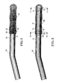
- the handle 10 shown in the drawing is surrounded by a handle 20 at its handle end 11.
- a securing element 30 is attached to the handle 20 by means of a clip-like fastening section 31.
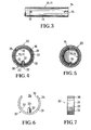
- the handle 20 has a cylindrical cavity 21 and is provided with a passage opening 22 for a pin-shaped securing section 32 and a recess 23 designed as a groove-shaped thickening for the fastening section 31 of the securing element 30.
- a passage opening 22 for a pin-shaped securing section 32 and a recess 23 designed as a groove-shaped thickening for the fastening section 31 of the securing element 30 On the inside of the handle 2 facing the end section 14 of the handle end 11, two diametrically opposite, radially inwardly projecting rib-like projections 24 are provided.
- the stem wall 13 is provided with a recess 12 and at the end section 14 with two diametrically opposite slot-like depressions 15.
- a rigid pin-shaped securing section 32 extends from the fastening section 31 of the securing element 30 into the passage opening 22 of the handle 20 and the recess 12 of the handle wall 13.
- Fig. 3 the stem end 11 of the style 10 is shown.
- the recess 12 is a round bore, while the recesses 15 are slits made at the end portion 14 of the stem 10.
- the attachment of the handle 20 to the handle end 11 of the handle 10 can be seen particularly clearly in FIG. 4.
- the rounded, pin-shaped securing section 32 of the securing element 30 extends through the passage opening 22 of the handle 20 and through the recess 12 of the handle end 11, while the fastening section 31 of the securing element 30 is snapped into the recess 23 of the handle 20 in a form-fitting manner due to its inherent elasticity.
- the securing section 32 is provided on the inside 37 of the fastening section 31 opposite the opening 34.
- the handle 20 is first attached to the handle end 11 of the handle 10 with little play without securing element 30 until the projections 24 come to rest against the end section 14. Then the handle 20 is rotated relative to the handle 10 until the projections 24 provided in the cavity 21 of the handle 20 into the recesses 15 engage at end portion 14 of stem 10. The position of the projections 24 can be seen from the outside in that the one projection 24 is formed in the passage opening 22. Subsequently, the handle 20 is pushed onto the handle end 11 as far as it will go, the projections 24 frictionally engaging in the recesses 15. In this position, the passage opening 22 of the handle 20 and the recess 12 of the handle 10 overlap intervenes.
- the securing element 30 forms an integral part of the handle 20 in the assembled state.
Landscapes
- Engineering & Computer Science (AREA)
- Mechanical Engineering (AREA)
- Cleaning Implements For Floors, Carpets, Furniture, Walls, And The Like (AREA)
- Mechanical Control Devices (AREA)
Applications Claiming Priority (2)
| Application Number | Priority Date | Filing Date | Title |
|---|---|---|---|
| DE9005307U DE9005307U1 (de) | 1990-05-10 | 1990-05-10 | Stiel mit Handgriff |
| DE9005307U | 1990-05-10 |
Publications (1)
| Publication Number | Publication Date |
|---|---|
| EP0456021A1 true EP0456021A1 (fr) | 1991-11-13 |
Family
ID=6853671
Family Applications (1)
| Application Number | Title | Priority Date | Filing Date |
|---|---|---|---|
| EP91106306A Withdrawn EP0456021A1 (fr) | 1990-05-10 | 1991-04-19 | Manche avec poignée |
Country Status (3)
| Country | Link |
|---|---|
| EP (1) | EP0456021A1 (fr) |
| DE (1) | DE9005307U1 (fr) |
| FI (1) | FI912245A7 (fr) |
Cited By (3)
| Publication number | Priority date | Publication date | Assignee | Title |
|---|---|---|---|---|
| EP0779130A1 (fr) * | 1995-12-16 | 1997-06-18 | Kilpatrick Fraser Limited | Clip pour clé à chocs |
| DE10108998C2 (de) * | 2000-02-24 | 2003-03-20 | Chang Chuck | Griffkonstruktion zum Einstellen des Kraftarmes eines Werkzeuges |
| USD1087512S1 (en) * | 2021-03-31 | 2025-08-05 | George M. Kelly, Jr. | Broom handle |
Citations (9)
| Publication number | Priority date | Publication date | Assignee | Title |
|---|---|---|---|---|
| US2110397A (en) * | 1937-01-29 | 1938-03-08 | Kangas Francis | Drill |
| FR1010993A (fr) * | 1948-11-17 | 1952-06-17 | Perfectionnement aux goupilles et analogues | |
| GB1533631A (en) * | 1976-12-22 | 1978-11-29 | Betterwear Prod Ltd | Method of securing a head and handle together |
| US4266453A (en) * | 1979-04-16 | 1981-05-12 | Farley D Gray | Socket retaining ring |
| US4304500A (en) * | 1980-04-18 | 1981-12-08 | Texaco Inc. | Retainer for impact tool couplings |
| BE902835A (nl) * | 1985-07-09 | 1985-11-04 | Durol Pvba | Verbeterde stokdweil of zwabber |
| EP0187952A1 (fr) * | 1984-12-17 | 1986-07-23 | D. Gray Farley | Goupille avec un manteau de sécurité métallique |
| DE8807974U1 (de) * | 1988-06-21 | 1988-09-08 | Szukay, Hans-Joachim, 5060 Bergisch Gladbach | Drahtformfeder-Sicherung für Maschinenschrauber-Werkzeuge |
| EP0283445A1 (fr) * | 1987-03-20 | 1988-09-21 | COLTELLERIE MONTANA S.r.l. | Couteau à usages ménagers et professionnels |
-
1990
- 1990-05-10 DE DE9005307U patent/DE9005307U1/de not_active Expired - Lifetime
-
1991
- 1991-04-19 EP EP91106306A patent/EP0456021A1/fr not_active Withdrawn
- 1991-05-09 FI FI912245A patent/FI912245A7/fi not_active Application Discontinuation
Patent Citations (9)
| Publication number | Priority date | Publication date | Assignee | Title |
|---|---|---|---|---|
| US2110397A (en) * | 1937-01-29 | 1938-03-08 | Kangas Francis | Drill |
| FR1010993A (fr) * | 1948-11-17 | 1952-06-17 | Perfectionnement aux goupilles et analogues | |
| GB1533631A (en) * | 1976-12-22 | 1978-11-29 | Betterwear Prod Ltd | Method of securing a head and handle together |
| US4266453A (en) * | 1979-04-16 | 1981-05-12 | Farley D Gray | Socket retaining ring |
| US4304500A (en) * | 1980-04-18 | 1981-12-08 | Texaco Inc. | Retainer for impact tool couplings |
| EP0187952A1 (fr) * | 1984-12-17 | 1986-07-23 | D. Gray Farley | Goupille avec un manteau de sécurité métallique |
| BE902835A (nl) * | 1985-07-09 | 1985-11-04 | Durol Pvba | Verbeterde stokdweil of zwabber |
| EP0283445A1 (fr) * | 1987-03-20 | 1988-09-21 | COLTELLERIE MONTANA S.r.l. | Couteau à usages ménagers et professionnels |
| DE8807974U1 (de) * | 1988-06-21 | 1988-09-08 | Szukay, Hans-Joachim, 5060 Bergisch Gladbach | Drahtformfeder-Sicherung für Maschinenschrauber-Werkzeuge |
Cited By (3)
| Publication number | Priority date | Publication date | Assignee | Title |
|---|---|---|---|---|
| EP0779130A1 (fr) * | 1995-12-16 | 1997-06-18 | Kilpatrick Fraser Limited | Clip pour clé à chocs |
| DE10108998C2 (de) * | 2000-02-24 | 2003-03-20 | Chang Chuck | Griffkonstruktion zum Einstellen des Kraftarmes eines Werkzeuges |
| USD1087512S1 (en) * | 2021-03-31 | 2025-08-05 | George M. Kelly, Jr. | Broom handle |
Also Published As
| Publication number | Publication date |
|---|---|
| FI912245L (fi) | 1991-11-11 |
| DE9005307U1 (de) | 1990-07-12 |
| FI912245A0 (fi) | 1991-05-09 |
| FI912245A7 (fi) | 1991-11-11 |
Similar Documents
| Publication | Publication Date | Title |
|---|---|---|
| DE69509928T2 (de) | Verbesserungen an Verriegelungsringen | |
| EP1277420B1 (fr) | Brosse à dents | |
| WO2005046506A1 (fr) | Partie de brosse pour brosse a dents electrique | |
| EP0339357A2 (fr) | Outil de coupe | |
| DD202498A5 (de) | Zahnbuerste mit verschieden abgewinkeltem kopf | |
| EP0406566B1 (fr) | Mécanisme pour manipulation de rotation | |
| CH644008A5 (de) | Elektrisches handgeraet, insbesondere elektrische zahnbuerste. | |
| DE2901213C2 (de) | Lösbare Stiftverbindung für Bauelemente | |
| DE3832694C2 (fr) | ||
| DE4428496A1 (de) | Kugelgelenk | |
| EP0456021A1 (fr) | Manche avec poignée | |
| DE3246887C2 (de) | Stielbefestigungskupplung, insbesondere für Haus- und Gartengeräte | |
| DE4314173A1 (de) | Verbindungselement zur lösbaren Verbindung eines Arbeitsgerätes mit einem Arbeitsstiel | |
| DE4429063A1 (de) | Werkzeug mit Handgriff, insbesondere Haushaltsmesser | |
| DE8602547U1 (de) | Auftragsgerät mit einem auswechselbaren Auftragsorgan | |
| DE3603876C2 (fr) | ||
| WO2004024012A1 (fr) | Clou d'osteosynthese centro-medullaire servant a soigner des fractures des os longs | |
| DE10357104A1 (de) | Medizinisches Instrument | |
| DE212018000325U1 (de) | Vorrichtung zum Reinigen von Zahnzwischenräumen | |
| DE10215647A1 (de) | Rohrschelle | |
| DE102018133028B4 (de) | Reinigungsgerät | |
| DE9111109U1 (de) | Aufwickelvorrichtung für Binden oder Bandagen | |
| EP0979740B1 (fr) | Instrument d'écriture | |
| DE19706560A1 (de) | Ringschloß zum Sichern von beweglichen Gegenständen, insbesondere Zweirädern oder dergleichen Fahrzeuge | |
| DE19905361B4 (de) | Vorrichtung zum Auf- und Abspulen einer Leine |
Legal Events
| Date | Code | Title | Description |
|---|---|---|---|
| PUAI | Public reference made under article 153(3) epc to a published international application that has entered the european phase |
Free format text: ORIGINAL CODE: 0009012 |
|
| AK | Designated contracting states |
Kind code of ref document: A1 Designated state(s): AT BE CH DE DK ES FR GB GR IT LI LU NL SE |
|
| STAA | Information on the status of an ep patent application or granted ep patent |
Free format text: STATUS: THE APPLICATION IS DEEMED TO BE WITHDRAWN |
|
| 18D | Application deemed to be withdrawn |
Effective date: 19920514 |