EP0456025B1 - Hochspannungsschalter mit Hilfslichtbogen in Reihe - Google Patents
Hochspannungsschalter mit Hilfslichtbogen in Reihe Download PDFInfo
- Publication number
- EP0456025B1 EP0456025B1 EP91106454A EP91106454A EP0456025B1 EP 0456025 B1 EP0456025 B1 EP 0456025B1 EP 91106454 A EP91106454 A EP 91106454A EP 91106454 A EP91106454 A EP 91106454A EP 0456025 B1 EP0456025 B1 EP 0456025B1
- Authority
- EP
- European Patent Office
- Prior art keywords
- tube
- contact
- volume
- fixed
- blast
- Prior art date
- Legal status (The legal status is an assumption and is not a legal conclusion. Google has not performed a legal analysis and makes no representation as to the accuracy of the status listed.)
- Expired - Lifetime
Links
- 229910052751 metal Inorganic materials 0.000 claims description 18
- 239000002184 metal Substances 0.000 claims description 18
- 238000005422 blasting Methods 0.000 abstract 1
- 230000001737 promoting effect Effects 0.000 abstract 1
- 238000007664 blowing Methods 0.000 description 12
- 239000011324 bead Substances 0.000 description 8
- 230000000694 effects Effects 0.000 description 4
- 239000011810 insulating material Substances 0.000 description 3
- 239000000463 material Substances 0.000 description 3
- 239000000956 alloy Substances 0.000 description 2
- 229910045601 alloy Inorganic materials 0.000 description 2
- 238000012550 audit Methods 0.000 description 2
- 229910018503 SF6 Inorganic materials 0.000 description 1
- 230000015556 catabolic process Effects 0.000 description 1
- 238000010276 construction Methods 0.000 description 1
- 238000000354 decomposition reaction Methods 0.000 description 1
- 238000006731 degradation reaction Methods 0.000 description 1
- 238000009434 installation Methods 0.000 description 1
- 238000003754 machining Methods 0.000 description 1
- 238000012423 maintenance Methods 0.000 description 1
- 238000004519 manufacturing process Methods 0.000 description 1
- 229910052573 porcelain Inorganic materials 0.000 description 1
- SFZCNBIFKDRMGX-UHFFFAOYSA-N sulfur hexafluoride Chemical compound FS(F)(F)(F)(F)F SFZCNBIFKDRMGX-UHFFFAOYSA-N 0.000 description 1
- 229960000909 sulfur hexafluoride Drugs 0.000 description 1
- WFKWXMTUELFFGS-UHFFFAOYSA-N tungsten Chemical compound [W] WFKWXMTUELFFGS-UHFFFAOYSA-N 0.000 description 1
- 229910052721 tungsten Inorganic materials 0.000 description 1
- 239000010937 tungsten Substances 0.000 description 1
Images
Classifications
-
- H—ELECTRICITY
- H01—ELECTRIC ELEMENTS
- H01H—ELECTRIC SWITCHES; RELAYS; SELECTORS; EMERGENCY PROTECTIVE DEVICES
- H01H33/00—High-tension or heavy-current switches with arc-extinguishing or arc-preventing means
- H01H33/70—Switches with separate means for directing, obtaining, or increasing flow of arc-extinguishing fluid
- H01H33/88—Switches with separate means for directing, obtaining, or increasing flow of arc-extinguishing fluid the flow of arc-extinguishing fluid being produced or increased by movement of pistons or other pressure-producing parts
- H01H33/90—Switches with separate means for directing, obtaining, or increasing flow of arc-extinguishing fluid the flow of arc-extinguishing fluid being produced or increased by movement of pistons or other pressure-producing parts this movement being effected by or in conjunction with the contact-operating mechanism
- H01H33/901—Switches with separate means for directing, obtaining, or increasing flow of arc-extinguishing fluid the flow of arc-extinguishing fluid being produced or increased by movement of pistons or other pressure-producing parts this movement being effected by or in conjunction with the contact-operating mechanism making use of the energy of the arc or an auxiliary arc
- H01H33/903—Switches with separate means for directing, obtaining, or increasing flow of arc-extinguishing fluid the flow of arc-extinguishing fluid being produced or increased by movement of pistons or other pressure-producing parts this movement being effected by or in conjunction with the contact-operating mechanism making use of the energy of the arc or an auxiliary arc and assisting the operating mechanism
Definitions
- the present invention relates to a dielectric gas circuit breaker with self-blowing, of the type comprising additional contacts making it possible to generate, during an opening operation, a secondary arc in series with the main arc, the energy of this arc secondary being used to operate the device.
- a circuit breaker of this type has for example been described in French Patent No. 2,610,763.
- An object of the present invention is to provide a circuit breaker of the aforementioned type of simple embodiment, in particular in the generating part of the secondary arc.
- Another object of the invention is to produce a circuit breaker not comprising sliding contacts in the area of the secondary arc; this area, in fact, is polluted by the decomposition products of the dielectric gas, which can cause a degradation of the quality of the sliding contacts.
- Another object of the invention is to provide a circuit breaker comprising no insulating piston, the construction of which is expensive and which is subject to wear requiring frequent replacement.
- Another object of the invention is to provide a circuit breaker with a mobile assembly which is light, so that it requires only a small operating energy for its operation.
- said third tube is fixed by an insulating tubular portion to a fourth tube electrically connected to a second outlet of the circuit breaker, said second tube has its second end also in electrical contact with fingers electrically connected to said fourth tube and the other of said auxiliary contacts is fixed to said fourth tube, said auxiliary contacts coming into contact with a tube integral with the movable assembly and comprising an insulating portion and a metal portion , the position and the respective length of these two tubular portions being chosen so that in the engaged position, at least one of the auxiliary contacts is in contact with the insulating portion and so that during an opening operation, the two auxiliary contacts first come simultaneously into contact with the metal portion, at least one of said auxiliary contacts then leaving this metal portion.
- the second end of said second tube is shaped as a bead carrying an outer cylindrical portion on which said fingers rest and a portion internal cylindrical bearing sliding contacts cooperating with said fourth tube.
- the blowing piston is fitted with a calibrated one-way valve letting the gas pass from the inside to the outside of the blowing volume.
- the blowing piston is fitted with a one-way valve allowing the passage of gas only from the outside to the inside of the blowing volume.
- the second piston is fitted with a one-way valve allowing the passage of gas only from the outside to the inside of the second volume.
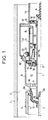
- a breaking chamber will be described; it is understood that a high-voltage circuit breaker may comprise, for each phase, several breaking chambers of the type which will now be described.
- the reference 1 designates an insulating envelope, preferably of porcelain, delimiting a chamber 2 filled with a gas with good dielectric properties, for example sulfur hexafluoride under a pressure of a few bars.
- the fixed assembly comprises an arcing contact 3, consisting of a metal tube whose end 3A is made of a material resistant to the effects of the arcing, by example an alloy based on tungsten.
- the fixed assembly also includes a main contact 4 consisting of fingers protected by a corona hood 5. The arcing contact and the fixed contact are electrically connected to a first socket, not shown.
- the movable assembly comprises an operating part 6, consisting of a tube of insulating material passing through the chamber 2 in a sealed manner and connected to a mechanism not shown.
- a metal assembly comprising two tubes 7 and 8, coaxial and connected by a metal ring 9. These tubes and this ring are preferably made in one piece from machining.
- the tube 7 constitutes the movable arcing contact; its end 7A is made of material resistant to the effects of the arc and cooperates with the contact 3-3A.
- the tube 8 has a first end 8A, of reduced diameter, and carrying a blowing nozzle 10 made of insulating material.
- the tubular portion 8A constitutes the main movable contact of the circuit breaker and cooperates, when the circuit breaker is in the engaged position, as shown in FIG. 1, with the fingers 4.
- the contact is effected by a portion of external cylindrical surface of the bead 8B.
- bead 8B preferably forms a single piece with the tubes 7 and 8 and the crown 9.
- the piston includes seals 17; it is provided with a calibrated valve 18 to limit the pressure inside the volume V1; this valve will be used, as we will see, when cutting low currents.
- the piston finally comprises a one-way valve 19, authorizing the passage of gas only from the outside to the inside of the volume V1; this valve is a simple washer applied to holes 20 passing through the piston.
- the crown 9 is pierced with holes 9A.
- the bead 8B carries, on a cylindrical inner surface, sliding electrical contacts 22 bearing on the tube 14.
- the bead 8B is pierced with holes 23 intended to lighten it and facilitate the circulation of the gas.
- the tube 14 and the tube 11 carry, on either side of the insulating portion 15 two auxiliary contact elements 25 and 26 intended to form a secondary arc.
- These elements consist of tube portions whose ends are made of an alloy resistant to the effects of the arc.
- the contacts 25 and 26 cooperate with a switching tube fixed to the tube 7, therefore movable with it, and comprising an insulating portion 28 and a metal portion 29 the end of which is made of material resistant to the effects of the arc.
- the circuit breaker further comprises a metal piston 30, integral with the operating tube 6, provided with a gasket 31 and a one-way valve 32 allowing the passage of gas only from the outside to the inside of the volume V2 constituted by the tubes 7 and 14, and the pistons 16 and 30.
- the circuit breaker works as follows: in the on position ( Figure 1), the current flows through the fingers 4, the tube 8A-8-8B, the fingers 13, the crown 12 and the tube 11.
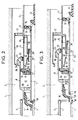
- the operating tube is actuated and moves to the right of the figure.
- the main contacts 4 and 8A separate (figure 2) and the current is switched on the arcing contacts 3 and 7A; the fingers 13 leave the bead 8A, but the contacts 25 and 26 come into contact with the metal portion of the switching tube; in this way, the current takes the following path: the tube 3, the tube 7, the crown 9, the tube 8, the bead 8B, the contacts 22, the tube 14, the contact 25, the tube 29, the contact 26 and tube 11.
- the closing of the circuit breaker is caused by the movement to the left of the figures of the operating tube 6.
- the valves 19 open during this maneuver, so that there is no need to overcome either depression or overpressure; the closing operation also requires only a low operating energy.
- the circuit breaker of the invention has a simple structure, therefore economical, compact, therefore robust and rigid, without electrical contacts in the arcing zones, therefore of reduced maintenance.
- the invention applies to the production of high voltage circuit breakers.
Landscapes
- Circuit Breakers (AREA)
- Arc-Extinguishing Devices That Are Switches (AREA)
- Circuit Arrangements For Discharge Lamps (AREA)
- Arc Welding Control (AREA)
- Lasers (AREA)
- Organic Insulating Materials (AREA)
Claims (5)
- Hochspannungsschalter mit unter Druck stehende dielektrischen Gas, der für jede Phase mindestens eine Trennkammer aufweist, die eine mit dem Gas gefüllte isolierende Umhüllung und in dieser aufweist:- eine ortsfeste Einheit mit einem ortsfesten Hauptkontakt (4) und einem ortsfesten Lichtbogenkontakt (3-3A), die elektrisch an einen ersten Stromanschluß angeschlossen sind,- eine bewegliche Einheit mit einem Betätigungsorgan (6), das mit einem Bauteil fest verbunden ist, das von einem ersten den beweglichen Lichtbogenkontakt bildenden Rohr (7-7A) und von einem zweiten, zum ersten Rohr koaxialen Rohr (8-8A-8B) gebildet wird, dessen erstes Ende (8A) der bewegliche Hauptkontakt ist und eine Blasdüse (10) trägt, wobei das erste Rohr und das zweite Rohr ein Blasvolumen (V1) begrenzen, das durch einen die Rohre miteinander verbindenden durchbrochenen Kranz (9) und einen ortsfesten Blaskolben (16) verschlossen wird,- zwei Hilfslichtbogenkontakte (25, 26), die sich in einem bezüglich des ortsfesten Blaskolbens (16) zum Blasvolumen entgegengesetzt liegenden zweiten Volumen (V2) befinden, wobei der feste Blaskolben (16) von einem dritten Metallrohr (14) gehalten wird, das zum ersten Rohr (7-7A) koaxial liegt und mit diesem ersten Rohr und einem mit dem ersten Rohr /(7-7A) fest verbundenen zweiten Kolben (30) das zweite Volumen bildet,wobei ein zweites Ende (8B) des zweiten Rohrs mit dem dritten Rohr außerhalb dieses dritten Rohrs in elektrischem Kontakt steht und einer der Hilfskontakte (25) am dritten Rohr (14) befestigt ist,
dadurch gekennzeichnet, daß das dritte Rohr (14) mit einem isolierende Abschnitt (15) an einem vierten Rohr (11) befestigt ist, das elektrisch mit einem zweiten Stromanschluß des Schalters verbunden ist, daß das zweite Rohr mit seinem zweiten Ende (8B) weiter in elektrischem Kontakt mit Fingern (13) steht, die elektrisch mit dem vierten Rohr (11) verbunden sind, und daß der andere der beiden Hilfskontakte am vierten Rohr befestigt ist, wobei die Hilfskontakte mit einem Rohr (28-29) in Berührung gelangen, das Teil der beweglichen Einheit ist und einen isolierenden Abschnitt (28) sowie einen metallischen Abschnitt (29) aufweist, wobei die Lage und Länge der beiden rohrförmigen Abschnitte so gewählt sind, daß bei geschlossenem Schalter mindestens einer der Hilfskontakte (26) mit dem isolierenden Abschnitt (28) in Kontakt steht und daß während eines Trennvorgangs die beiden Hilfskontakte zuerst gleichzeitig mit dem metallischen Abschnitt (29) in Kontakt gelangen, worauf mindestens einer der Hilfskontakte (25) diesen metallischen Abschnitt (29 verläßt. - Schalter nach Anspruch 1, dadurch gekennzeichnet, daß das zweite Ende (8B) des zweiten Rohrs (8) wulstartig ausgebildet ist und einen äußeren zylindrischen Bereich, auf dem sich die Finger (13) abstützen, sowie einen zylindrischen Innenbereich aufweist, der mit dem vierten Rohr (14) zusammenwirkende Gleitkontakte (22) trägt.
- Schalter nach Anspruch 1 oder 2, dadurch gekennzeichnet, daß der ortsfeste Blaskolben (16) eine in einer Richtung wirksames Überdruckventil (18) besitzt, das das Gas nur von innerhalb des Blasvolumens (V1) nach außen durchläßt.
- Schalter nach einem der Ansprüche 1 bis 3, dadurch gekennzeichnet, daß der ortsfeste Blaskolben (16) ein Rückschlagventil (19) aufweist, das Gas nur von außerhalb des Blasvolumens (V1) ins Innere durchläßt.
- Schalter nach einem der Ansprüche 1 bis 4, dadurch gekennzeichnet, daß der zweite Kolben (30) ein Rückschlagventil enthält, das Gas nur von außerhalb des zweiten Volumens (V2) ins Innere durchläßt.
Applications Claiming Priority (2)
| Application Number | Priority Date | Filing Date | Title |
|---|---|---|---|
| FR9005326 | 1990-04-26 | ||
| FR9005326A FR2661550B1 (fr) | 1990-04-26 | 1990-04-26 | Disjoncteur a haute tension a arc serie. |
Publications (2)
| Publication Number | Publication Date |
|---|---|
| EP0456025A1 EP0456025A1 (de) | 1991-11-13 |
| EP0456025B1 true EP0456025B1 (de) | 1995-03-01 |
Family
ID=9396115
Family Applications (1)
| Application Number | Title | Priority Date | Filing Date |
|---|---|---|---|
| EP91106454A Expired - Lifetime EP0456025B1 (de) | 1990-04-26 | 1991-04-22 | Hochspannungsschalter mit Hilfslichtbogen in Reihe |
Country Status (10)
| Country | Link |
|---|---|
| US (1) | US5160818A (de) |
| EP (1) | EP0456025B1 (de) |
| JP (1) | JP2563855B2 (de) |
| CN (1) | CN1023924C (de) |
| AT (1) | ATE119312T1 (de) |
| BR (1) | BR9101564A (de) |
| CA (1) | CA2041234C (de) |
| DE (1) | DE69107670T2 (de) |
| ES (1) | ES2070357T3 (de) |
| FR (1) | FR2661550B1 (de) |
Families Citing this family (6)
| Publication number | Priority date | Publication date | Assignee | Title |
|---|---|---|---|---|
| FR2720188B1 (fr) * | 1994-05-19 | 1996-06-14 | Gec Alsthom T & D Sa | Disjoncteur à autocompression réduite. |
| DE19524217A1 (de) * | 1995-07-03 | 1997-01-09 | Abb Research Ltd | Leistungsschalter |
| CN101930871B (zh) * | 2010-08-25 | 2012-11-21 | 中国西电电气股份有限公司 | 一种高压开关设备用高载流能力灭弧室 |
| KR101483086B1 (ko) * | 2013-05-21 | 2015-01-16 | 한국전기연구원 | 열팽창실 압력 제어형 복합 소호 가스차단기 |
| CN106328430B (zh) * | 2016-08-25 | 2018-08-07 | 中国西电电气股份有限公司 | 一种串联压气室的灭弧室 |
| US10026571B1 (en) * | 2017-03-31 | 2018-07-17 | General Electric Technology Gmbh | Switching chamber for a gas-insulated circuit breaker comprising an optimized thermal channel |
Family Cites Families (8)
| Publication number | Priority date | Publication date | Assignee | Title |
|---|---|---|---|---|
| DE2349263C2 (de) * | 1973-10-01 | 1982-08-26 | Brown, Boveri & Cie Ag, 6800 Mannheim | Elektrischer Druckgasschalter |
| JP2528100B2 (ja) * | 1986-07-08 | 1996-08-28 | 株式会社日立製作所 | パツフア形ガス遮断器 |
| FR2610763B1 (fr) * | 1987-02-09 | 1989-04-28 | Alsthom | Disjoncteur a faible energie de manoeuvre |
| FR2619246B1 (fr) * | 1987-08-03 | 1989-11-17 | Alsthom | Disjoncteur a haute ou moyenne tension a gaz sous pression a energie de coupure prelevee sur celle de l'arc |
| FR2629260B1 (fr) * | 1988-03-23 | 1994-07-08 | Alsthom | Disjoncteur a haute tension a faible energie de manoeuvre |
| FR2638564B1 (fr) * | 1988-11-02 | 1990-11-30 | Alsthom Gec | Disjoncteur a haute tension a gaz dielectrique sous pression |
| FR2647949B1 (fr) * | 1989-05-31 | 1994-02-18 | Gec Alsthom Sa | Disjoncteur a haute tension a gaz dielectrique de soufflage |
| FR2649531B1 (fr) * | 1989-07-04 | 1995-11-10 | Alsthom Gec | Disjoncteur a haute ou moyenne tension |
-
1990
- 1990-04-26 FR FR9005326A patent/FR2661550B1/fr not_active Expired - Lifetime
-
1991
- 1991-04-18 BR BR919101564A patent/BR9101564A/pt not_active Application Discontinuation
- 1991-04-22 ES ES91106454T patent/ES2070357T3/es not_active Expired - Lifetime
- 1991-04-22 DE DE69107670T patent/DE69107670T2/de not_active Expired - Fee Related
- 1991-04-22 EP EP91106454A patent/EP0456025B1/de not_active Expired - Lifetime
- 1991-04-22 AT AT91106454T patent/ATE119312T1/de not_active IP Right Cessation
- 1991-04-22 US US07/688,797 patent/US5160818A/en not_active Expired - Fee Related
- 1991-04-24 CN CN91103342.4A patent/CN1023924C/zh not_active Expired - Fee Related
- 1991-04-25 CA CA002041234A patent/CA2041234C/fr not_active Expired - Fee Related
- 1991-04-26 JP JP3097392A patent/JP2563855B2/ja not_active Expired - Lifetime
Also Published As
| Publication number | Publication date |
|---|---|
| EP0456025A1 (de) | 1991-11-13 |
| JP2563855B2 (ja) | 1996-12-18 |
| BR9101564A (pt) | 1991-12-10 |
| JPH05159671A (ja) | 1993-06-25 |
| US5160818A (en) | 1992-11-03 |
| CN1023924C (zh) | 1994-03-02 |
| ATE119312T1 (de) | 1995-03-15 |
| FR2661550A1 (fr) | 1991-10-31 |
| ES2070357T3 (es) | 1995-06-01 |
| CA2041234C (fr) | 1994-11-22 |
| CN1056767A (zh) | 1991-12-04 |
| FR2661550B1 (fr) | 1992-06-12 |
| DE69107670D1 (de) | 1995-04-06 |
| DE69107670T2 (de) | 1995-06-29 |
Similar Documents
| Publication | Publication Date | Title |
|---|---|---|
| EP0388323A1 (de) | Elektrischer Autoexpansionsschalter mit Isoliergas | |
| EP0821382B1 (de) | Hochspannungsschalter mit Selbstbeblasung | |
| EP0591039B1 (de) | Hochspannung selbst-Blaslastscharter mit Schnittkammer mit reduzierter Gaskompression | |
| EP0367072B1 (de) | Hochspannungsdruckgasschalter | |
| EP0302390B1 (de) | Druckgasschalter für Hoch- oder Mittelspannung mit von der Lichtbogenenergie entnommener Ausschaltenergie | |
| EP0456025B1 (de) | Hochspannungsschalter mit Hilfslichtbogen in Reihe | |
| CA2206950C (fr) | Disjoncteur a haute tension avec insertion de resistance a la fermeture. | |
| EP0807946A1 (de) | Hochspannungs-Blaskolbenschalter | |
| FR2576144A1 (fr) | Disjoncteur a haute tension, a gaz comprime, a faible energie de manoeuvre | |
| EP0398211B1 (de) | Hochspannungs-Lastschalter mit dielektrischem Löschgas | |
| FR2629260A1 (fr) | Disjoncteur a haute tension a faible energie de manoeuvre | |
| EP0415098B1 (de) | Selbstblasschalter für Mittelspannung | |
| FR2610763A1 (fr) | Disjoncteur a faible energie de manoeuvre | |
| EP0398213B1 (de) | Mittelspannungsschalter für hohen Nennstrom | |
| EP0450567B1 (de) | Hoch- oder Mittelspannungs-Schalter mit aufeinanderstossenden Lichtbogenkontakten | |
| EP0785562A1 (de) | Lastschalter mit Kontakten mit Doppelbewegung | |
| EP0458236B1 (de) | Mittelspannungsschalter | |
| CA2017804C (fr) | Disjoncteur a haute tension a gaz dielectrique de soufflage | |
| EP0515268A1 (de) | Varistor Einführvorrichtung, eingebaut in einem Hochspannungslastschalter | |
| EP0664552A1 (de) | Autopneumatischer Druckgasschalter mit Doppelbewegung | |
| CH688702A5 (fr) | Disjoncteur à haute tension ayant une chambre de coupure à volume de soufflage variable. | |
| FR2607621A1 (fr) | Disjoncteur a haute tension a gaz dielectrique a resistance de fermeture | |
| EP0701264A1 (de) | Selbstbeblasener lastschalter mit halbbeweglichem Kolben | |
| FR2509521A1 (fr) | Disjoncteur a haute tension sous enveloppe contenant un gaz isolant | |
| FR2556496A1 (fr) | Disjoncteur a gaz comprime |
Legal Events
| Date | Code | Title | Description |
|---|---|---|---|
| PUAI | Public reference made under article 153(3) epc to a published international application that has entered the european phase |
Free format text: ORIGINAL CODE: 0009012 |
|
| AK | Designated contracting states |
Kind code of ref document: A1 Designated state(s): AT BE CH DE DK ES FR GB GR IT LI LU NL SE |
|
| 17P | Request for examination filed |
Effective date: 19911218 |
|
| 17Q | First examination report despatched |
Effective date: 19940125 |
|
| GRAA | (expected) grant |
Free format text: ORIGINAL CODE: 0009210 |
|
| AK | Designated contracting states |
Kind code of ref document: B1 Designated state(s): AT BE CH DE DK ES FR GB GR IT LI LU NL SE |
|
| PG25 | Lapsed in a contracting state [announced via postgrant information from national office to epo] |
Ref country code: NL Free format text: LAPSE BECAUSE OF NON-PAYMENT OF DUE FEES Effective date: 19950301 Ref country code: GR Free format text: LAPSE BECAUSE OF FAILURE TO SUBMIT A TRANSLATION OF THE DESCRIPTION OR TO PAY THE FEE WITHIN THE PRESCRIBED TIME-LIMIT Effective date: 19950301 Ref country code: GB Effective date: 19950301 Ref country code: DK Effective date: 19950301 |
|
| REF | Corresponds to: |
Ref document number: 119312 Country of ref document: AT Date of ref document: 19950315 Kind code of ref document: T |
|
| REF | Corresponds to: |
Ref document number: 69107670 Country of ref document: DE Date of ref document: 19950406 |
|
| PG25 | Lapsed in a contracting state [announced via postgrant information from national office to epo] |
Ref country code: LU Free format text: LAPSE BECAUSE OF NON-PAYMENT OF DUE FEES Effective date: 19950430 Ref country code: BE Effective date: 19950430 |
|
| ITF | It: translation for a ep patent filed | ||
| REG | Reference to a national code |
Ref country code: ES Ref legal event code: FG2A Ref document number: 2070357 Country of ref document: ES Kind code of ref document: T3 |
|
| NLV1 | Nl: lapsed or annulled due to failure to fulfill the requirements of art. 29p and 29m of the patents act | ||
| GBV | Gb: ep patent (uk) treated as always having been void in accordance with gb section 77(7)/1977 [no translation filed] |
Effective date: 19950301 |
|
| BERE | Be: lapsed |
Owner name: S.A. GEC ALSTHOM Effective date: 19950430 |
|
| PLBE | No opposition filed within time limit |
Free format text: ORIGINAL CODE: 0009261 |
|
| STAA | Information on the status of an ep patent application or granted ep patent |
Free format text: STATUS: NO OPPOSITION FILED WITHIN TIME LIMIT |
|
| 26N | No opposition filed | ||
| PGFP | Annual fee paid to national office [announced via postgrant information from national office to epo] |
Ref country code: SE Payment date: 19970324 Year of fee payment: 7 Ref country code: AT Payment date: 19970324 Year of fee payment: 7 |
|
| PGFP | Annual fee paid to national office [announced via postgrant information from national office to epo] |
Ref country code: CH Payment date: 19970326 Year of fee payment: 7 |
|
| PGFP | Annual fee paid to national office [announced via postgrant information from national office to epo] |
Ref country code: ES Payment date: 19970418 Year of fee payment: 7 |
|
| PG25 | Lapsed in a contracting state [announced via postgrant information from national office to epo] |
Ref country code: AT Free format text: LAPSE BECAUSE OF NON-PAYMENT OF DUE FEES Effective date: 19980422 |
|
| PG25 | Lapsed in a contracting state [announced via postgrant information from national office to epo] |
Ref country code: SE Free format text: LAPSE BECAUSE OF NON-PAYMENT OF DUE FEES Effective date: 19980423 Ref country code: ES Free format text: LAPSE BECAUSE OF NON-PAYMENT OF DUE FEES Effective date: 19980423 |
|
| PG25 | Lapsed in a contracting state [announced via postgrant information from national office to epo] |
Ref country code: LI Free format text: LAPSE BECAUSE OF NON-PAYMENT OF DUE FEES Effective date: 19980430 Ref country code: CH Free format text: LAPSE BECAUSE OF NON-PAYMENT OF DUE FEES Effective date: 19980430 |
|
| REG | Reference to a national code |
Ref country code: CH Ref legal event code: PL |
|
| EUG | Se: european patent has lapsed |
Ref document number: 91106454.1 |
|
| PGFP | Annual fee paid to national office [announced via postgrant information from national office to epo] |
Ref country code: FR Payment date: 19990324 Year of fee payment: 9 |
|
| PGFP | Annual fee paid to national office [announced via postgrant information from national office to epo] |
Ref country code: DE Payment date: 20000320 Year of fee payment: 10 |
|
| REG | Reference to a national code |
Ref country code: ES Ref legal event code: FD2A Effective date: 20000403 |
|
| PG25 | Lapsed in a contracting state [announced via postgrant information from national office to epo] |
Ref country code: FR Free format text: LAPSE BECAUSE OF NON-PAYMENT OF DUE FEES Effective date: 20001229 |
|
| REG | Reference to a national code |
Ref country code: FR Ref legal event code: ST |
|
| PG25 | Lapsed in a contracting state [announced via postgrant information from national office to epo] |
Ref country code: DE Free format text: LAPSE BECAUSE OF NON-PAYMENT OF DUE FEES Effective date: 20020201 |
|
| PG25 | Lapsed in a contracting state [announced via postgrant information from national office to epo] |
Ref country code: IT Free format text: LAPSE BECAUSE OF NON-PAYMENT OF DUE FEES;WARNING: LAPSES OF ITALIAN PATENTS WITH EFFECTIVE DATE BEFORE 2007 MAY HAVE OCCURRED AT ANY TIME BEFORE 2007. THE CORRECT EFFECTIVE DATE MAY BE DIFFERENT FROM THE ONE RECORDED. Effective date: 20050422 |