EP0456056A1 - Composant d'accouplement et méthode de fabrication d'un tel composant - Google Patents
Composant d'accouplement et méthode de fabrication d'un tel composant Download PDFInfo
- Publication number
- EP0456056A1 EP0456056A1 EP91106813A EP91106813A EP0456056A1 EP 0456056 A1 EP0456056 A1 EP 0456056A1 EP 91106813 A EP91106813 A EP 91106813A EP 91106813 A EP91106813 A EP 91106813A EP 0456056 A1 EP0456056 A1 EP 0456056A1
- Authority
- EP
- European Patent Office
- Prior art keywords
- tube
- friction shoe
- mold
- shoe assemblies
- mounting material
- Prior art date
- Legal status (The legal status is an assumption and is not a legal conclusion. Google has not performed a legal analysis and makes no representation as to the accuracy of the status listed.)
- Granted
Links
- 230000000712 assembly Effects 0.000 claims abstract description 119
- 238000000429 assembly Methods 0.000 claims abstract description 119
- 239000000463 material Substances 0.000 claims abstract description 99
- 230000008878 coupling Effects 0.000 claims abstract description 51
- 238000010168 coupling process Methods 0.000 claims abstract description 51
- 238000005859 coupling reaction Methods 0.000 claims abstract description 51
- 239000013536 elastomeric material Substances 0.000 claims abstract description 13
- 239000012530 fluid Substances 0.000 claims abstract description 12
- 238000000034 method Methods 0.000 claims description 25
- 239000002184 metal Substances 0.000 claims description 17
- 238000000465 moulding Methods 0.000 claims description 14
- 238000010438 heat treatment Methods 0.000 claims description 3
- 239000002783 friction material Substances 0.000 claims description 2
- 230000000903 blocking effect Effects 0.000 claims 1
- 239000013013 elastic material Substances 0.000 abstract 1
- 238000004073 vulcanization Methods 0.000 description 7
- 238000004519 manufacturing process Methods 0.000 description 5
- 238000010276 construction Methods 0.000 description 3
- 230000003014 reinforcing effect Effects 0.000 description 3
- 125000006850 spacer group Chemical group 0.000 description 3
- 230000000694 effects Effects 0.000 description 1
- 230000008570 general process Effects 0.000 description 1
- 229920003052 natural elastomer Polymers 0.000 description 1
- 229920001194 natural rubber Polymers 0.000 description 1
- 229920001084 poly(chloroprene) Polymers 0.000 description 1
- 230000008569 process Effects 0.000 description 1
- 229920003051 synthetic elastomer Polymers 0.000 description 1
- 239000005061 synthetic rubber Substances 0.000 description 1
Images




Classifications
-
- F—MECHANICAL ENGINEERING; LIGHTING; HEATING; WEAPONS; BLASTING
- F16—ENGINEERING ELEMENTS AND UNITS; GENERAL MEASURES FOR PRODUCING AND MAINTAINING EFFECTIVE FUNCTIONING OF MACHINES OR INSTALLATIONS; THERMAL INSULATION IN GENERAL
- F16D—COUPLINGS FOR TRANSMITTING ROTATION; CLUTCHES; BRAKES
- F16D25/00—Fluid-actuated clutches
- F16D25/04—Fluid-actuated clutches in which the fluid actuates an elastic clutching, i.e. elastic actuating member, e.g. a diaphragm or a pneumatic tube
- F16D25/042—Fluid-actuated clutches in which the fluid actuates an elastic clutching, i.e. elastic actuating member, e.g. a diaphragm or a pneumatic tube the elastic actuating member rotating with the clutch
- F16D25/046—Fluid-actuated clutches in which the fluid actuates an elastic clutching, i.e. elastic actuating member, e.g. a diaphragm or a pneumatic tube the elastic actuating member rotating with the clutch and causing purely radial movement
Definitions
- the present invention relates to a coupling component in which a tube element is expanded to press friction shoe assemblies against a second coupling component.
- Known coupling assemblies such as a brake or clutch, include a coupling component having an inflatable annular tube which is mounted on a rigid annular rim.
- a plurality of friction shoe assemblies are connected with the tube in an annular array. When fluid pressure is conducted to the tube, the tube is expanded to press the friction shoe assemblies against another coupling component to interconnect the two coupling components.
- Coupling components having this general construction and mode of operation are disclosed in U.S. Patent Nos. 3,022,877; 3,092,231; 4,190,136; and 4,795,013.
- Coupling components having this construction have previously been made by a method which includes placing the inflatable annular tube in a mold, inflating the tube, and heating the mold to vulcanize the elastomeric material of the tube.
- the tube is then removed from the mold and friction shoe assemblies are connected with the tube.
- Friction shoe assemblies have previously been connected with the tube by inserting pins through holes or passages formed in the tube during vulcanising of the elastomeric material.
- the ends of the pins are received in openings formed in flanges on backing plates of the friction shoe assemblies.
- Releasable retainers, such as wires are used to prevent the pins from becoming disengaged from the backing plates of the friction shoe assemblies.
- the friction shoe assemblies When the friction shoe assemblies are connected with the tube by releasable pins or other types of torque transmitting elements, the friction shoe assemblies can be replaced when they become worn.
- a known coupling component has friction shoes which are bonded directly to the tube during the molding process.
- the inflatable tube is placed in the mold.
- the friction shoes are placed in an annular array in the mold with the friction shoes toward the tube.
- the tube is inflated and the mold heated to vulcanise the material of the tube and bond the tube with the friction shoes. Since the friction shoes are bonded with the tube, they cannot be replaced when they become worn.
- the present invention provides an improved method of forming an improved coupling component having a plurality of friction shoe assemblies connected with an inflatable tube by torque transmitting elements.
- the tube is placed in a mold.
- a plurality of friction shoe assemblies are placed in the mold with torque transmitting elements on the friction shoe assemblies adjacent to mounting material.
- Another object of this invention is to provide a new and improved coupling component having a plurality of friction shoe assemblies which are connected with the tube by releasable connectors and wherein mounting material connected with the tube is molded in place against the back of the friction shoes and around the releasable connectors.
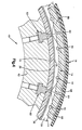
- a coupling component 10 (Fig. 1), constructed in accordance with the present invention, includes an annular array 12 of friction shoe assemblies 14.
- the friction shoe assemblies 14 are engageable with the outside of a drum or second coupling component (not shown) to interconnect the two coupling components.
- the coupling component 10 could function as part of either a brake or a clutch.
- the friction shoe assemblies 14 are moved into engagement with the drum by radial expansion of an inflatable tube 18.
- fluid pressure such as air pressure
- the tube expands radially inwardly. This causes the tube 18 to press the friction shoe assemblies 14 against the drum.
- the friction between the shoe assemblies 14 and drum interconnect the drum and the coupling component 10.
- a rigid annular metal rim 22 is connected with the inflatable tube 18.
- the rim 22 has an annular mounting flange 26 which is used to connect the coupling component 10 with an associated apparatus.
- the rim has a cylindrical web 28 with a radially inner side surface which is bonded to a radially outer side wall portion of the tube 18.
- reinforcing plies 32 are provided in the tube.
- the reinforcing plies 32 are surrounded by elastomeric mounting material, such as either natural or synthetic rubber.
- Each of the friction shoe assemblies 14 includes a rigid metal backing or base plate 36.
- a rectangular friction pad 38 is securely connected to the backing plate 36.
- Torque transmitting elements 40 and 42 interconnect the tube 18 and the backing plates 36.
- the torque transmitting elements 40 and 42 have surface areas which face circumferentially relative to the annular array 12 of friction shoe assemblies 14.
- the torque transmitting elements 40 and 42 transmit force from the backing plates 36 to the tube 18 when the coupling component 10 is engaged with another coupling component.
- the torque transmitting elements 40 and 42 are pins.
- the metal pins 40 and 42 are releasably connected with flanges on the backing plates 36 of the friction shoe assemblies 14.
- the releasable pins 40 and 42 enable the friction shoe assemblies 14 to be replaced when the friction pads 38 become worn.
- the pins 40 and 42 extend through the elastomeric mounting material connected with the tube 18 and through openings in the flanges on the metal backing plates 36. Therefore, the pins 40 and 42 interconnect the tube 18 and friction shoe assemblies 14.
- the metal pins 40 and 42 have surface areas which extend transversely to the backing plates 36 and face circumferentially of the annular array 12 of friction shoe assemblies 14. These surface areas press against the elastomeric mounting material to transmit torque from the friction shoe assemblies 14 to the tube 18.
- Suitable retainers such as snap rings or wires, are used to releasably hold the pins 40 and 42 in place on the backing plates 36.
- pins 40 and 42 are used as torque transmitting elements in the illustrated embodiment of the invention, it should be understood that the friction shoes could be provided with other known torque transmitting elements if desired.
- the other known torque transmitting elements could be used either separately or in combination with the pins 40 and 42.
- a drive bar could be used in conjunction with the pins 40 and 42 in the manner disclosed in U.S. Patent No. 4,795,013.
- Torque transmitting assemblies having the construction shown in U.S. Patents Nos. 3,022,877 and 4,190,136 could be used if desired.
- elastomeric mounting material connected with the tube 18 is molded in place against the backing plate 36 and around the torque transmitting elements or pins 40 and 42.
- a good fit is obtained between the backing plate and the elastomeric mounting material.
- the elastomeric mounting material obtains a secure grip on the pins to interconnect the friction shoe assemblies 14 and the tube 18. If a torque transmitting element other than the pins 40 and 42 is used, the elastomeric mounting material can be molded around or at least part way around, this torque transmitting element in much the same manner as in which it is molded around the pins.
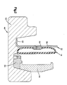
- the tube 18 and friction shoe assemblies 14 are placed in a multi-part mold 48 (Figs. 2-6).
- the annular tube 18 is expanded to press elastomeric mounting material against the friction shoe assemblies 14.
- the mold 48 is heated.
- the heated elastomeric mounting material is molded against the backing plates 36 and around the torque transmitting elements or pins 40 and 42 of the friction shoe assemblies.
- the reinforcing plies 32 have not been shown in Figs. 2, 3, 5 and 6 for purposes of clarity of illustration.
- annular bottom section 52 (Fig. 2) of a multi-part mold assembly 48 is supported on a horizontal surface. Therefore, the central axis of the annular metal bottom section 52 will be vertical and offset to the right as viewed in Fig. 2.
- An annular metal bottom ring 54 is placed on the bottom section 52 of the mold.
- the tube 18 Before the tube 18 is placed in the mold 48, the tube is mounted on the annular rim 22. At this time, the tube 18 is uncured and is held in place by an internally threaded connector member 56. Once the tube 18 has been mounted on the metal rim 22, the tube and rim are placed in the bottom section 52 of the mold (Fig. 2). At this time, the central axes of the annular rim 22 and tube 18 will be coincident with the vertical central axis of the bottom section 52 of the mold.
- a metal inner ring 62 is also placed in the bottom section 52 of the mold. The annular inner ring 62 has a central axis which is coincident with the central axis of the bottom section 52 of the mold 48.
- the friction shoe assemblies 14 are placed in an annular array in the mold (Fig. 3).
- the end portions of the torque transmitting elements or pins 40 engage openings in the bottom ring 54 to locate the friction shoe assemblies relative to the inner ring 62 and tube 18.
- the lower end portion 66 of each of the pins 40 engages a cylindrical locating hole or opening 68 in the bottom ring 54.
- the lower end portions of the pins 42 of the friction shoe assembly 14 engage holes or openings in the bottom ring 54.
- the openings 68 in the bottom ring 54 receiving the pins 40 and 42 are located so that the friction shoe assemblies 14 are disposed in an annular array with equal spacing between the ends of the friction shoe assemblies, in much the same manner as shown in Fig. 1.
- a plurality of metal ribs or spacer blocks 82 are provided in the inner ring 62.
- the spacer blocks 82 project radially outwardly from the annular rim 62 and extend between the friction shoe assemblies 14.
- the evenly spaced metal blocks 82 locate the friction shoe assemblies relative to each other and to the inner ring 62.
- the spacer blocks 82 have end portions or ribs 84 which extend across the width of the ends of the friction shoe assemblies 14.
- the ribs 84 block elastomeric mounting material from flowing into spaces between the ends of the friction shoe assemblies 14. This results in gaps being provided between the ends of the friction shoe assemblies 14.
- the gaps between friction shoe assemblies 14 (Fig. 1) enable the friction shoe assemblies to move toward each other when the tube 18 is inflated and expanded radially inwardly.
- additional elastomeric mounting material 88 (Figs. 4 and 5) is required in the mold between the friction shoe assemblies 14 and tube 18.
- the additional uncured elastomeric material 88 provides the necessary volume of elastomeric mounting material to flow around the torque transmitting elements or pins 40 and 42.
- the elastomeric mounting material 88 is also molded against the metal backing plate 36 of the friction shoe assembly 14. If desired, the elastomeric mounting material 88 could be placed in the mold 48 in conjunction with the tube 18 or placed in the mold 48 separately, or in conjunction with the friction shoe assemblies 14.
- the additional elastomeric mounting material 88 is provided in the form of blocks.
- the blocks 88 of uncured elastomeric material have a generally rectangular configuration and extend across the pins 40 and 42 of the friction shoe assemblies.
- the blocks 88 of elastomeric mounting material have recesses for receiving the pins 40 and 42. If desired, the blocks 88 of elastomeric mounting material could be provided with relatively deep grooves for the pins 40 and 42 to enable the material to extend further into the space between pins.
- the blocks 88 of elastomeric mounting material could be placed in the mold 48 separately from the friction shoe assemblies 14, or the friction shoe assemblies could be mounted on the blocks of material and then placed in the mold.
- the additional elastomeric mounting material 88 could be provided in blocks, the additional elastomeric mounting material could also be provided in a single elongated strip of material.
- the elongated strip of uncured elastomeric mounting material would have a rectangular cross sectional configuration and would be placed in the mold 48 between the tube 18 and friction shoe assemblies 14.
- the strip of elastomeric mounting material would be long enough to form a complete ring or circle extending around the annular array of friction shoe assemblies 14.
- the strip of elastomeric mounting material 88 could be provided with recesses for receiving the pins 40 and 42 of the various friction shoe assemblies 14. If desired, the friction shoe assemblies 14 could be mounted on the strip of elastomeric mounting material and then placed in the mold 48 with the strip of material. For example, the friction shoe assemblies 14 could be strung on a thin strip of elastomeric mounting material 88 which extends between the backing plates 36 and the pins 40 and 42 of the friction shoe assemblies. If desired, an additional strip of elastomeric mounting material 88 could be provided between the tube 18 and the pins 40 and 42.
- the annular inner portion of the side wall of the tube 18 would be formed with a greater radial thickness of uncured elastomeric mounting material than the rest of the tube. This would result in the one wall of the tube 18 having a strip of extra elastomeric mounting material extending around the annular array of friction shoe assemblies 14.
- the additional elastomeric mounting material connected with the radially inner portion of the tube 18 may be provided with recesses to receive the pins 40 and 42.
- the radially inner portion of the side wall of the tube 18 could be integrally formed with the additional elastomeric mounting material 88 rather than being formed separately from the elastomeric mounting material as shown in Fig. 5.
- annular metal top ring 92 is positioned over the friction shoe assemblies 14 opposite from the annular bottom ring 54.
- the annular top ring 92 is provided with pin receiving holes or openings 94 which are disposed axially opposite from and aligned with the pin receiving openings in the bottom ring 54.
- the upper end portion 96 of the pin 40 extends into an opening 94 in the top ring 92 to further locate the friction shoe assembly 14 and hold the friction shoe assembly in place.
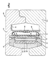
- a metal annular top section 102 is then placed over the top ring 92 and the upper end portions of the tube 18, rim 22, and inner ring 62 (Fig. 5).
- the top section 102 cooperates with the inner ring 62 and bottom section 52 of the multi-part mold 48 to close the mold.
- the bottom and top sections 48 and 102 of the mold are fixedly interconnected to hold the components of the mold 48, the friction shoe assemblies 14, and the rim 22 against movement relative to each other.
- the mold 48 may be heated by conducting steam through passages in the mold or by placing the mold between heated platens of a press. As the mold 48 is heated, the elastomeric mounting material 88 is softened and flows around the pins 40 and 42 (Fig. 6). In addition, the elastomeric mounting material 88 is pressed against the backing plates of the friction shoe assemblies 14.
- the elastomeric mounting material of the tube 18 and the extra elastomeric mounting material 88 are uncured. Continued application of heat and pressure to the elastomeric mounting material results in vulcanization of the uncured elastomeric material in a known manner.
- the tube 18 was filled with air at a pressure of approximately 80 p.s.i. and the mold 48 was heated to a temperature of approximately 300°F, for several hours. It should be understood that any desired vulcanization process could be used so that the temperatures and duration of the vulcanization process will depend upon the composition of the elastomeric mounting material.
- the elastomeric mounting material 88 and the elastomeric material of the tube 18 was neoprene. Of course, other elastomeric materials, including elastomeric mounting materials which do not require vulcanization, could be utilized if desired.
- the tube 18 is expanded radially inwardly to press the friction shoe assemblies 14 against the outer side surface of a drum.
- the tube is expanded radially outwardly to press the friction shoe assemblies against the inside surface of a hollow drum or other coupling component. Since the embodiment of the invention illustrated in Fig. 7 is generally similar to the embodiment of the invention illustrated in Fig. 1, similar numerals will be utilized to identify similar components, the suffix letter "a" being associated with the numerals of Fig. 7 to avoid confusion.
- the coupling component 10a includes an annular array 12a of friction shoe assemblies 14a.
- the friction shoe assemblies 14a are connected with an inflatable tube 18a.
- the tube 18a expands radially outwardly to press the friction shoe assemblies 14a against a cylindrical inner side surface of a hollow drum (not shown) forming a second component of the coupling.
- the friction shoe assemblies 14a have a metal backing or base plate 36a upon which a generally rectangular pad 38a of friction material is disposed.
- a pair of torque transmitting elements or pins 40a and 42a releasably connect the friction shoe assembly 14a with the tube 18a.
- the central portions of the pins 40a and 42a are surrounded by elastomeric mounting material which is connected with the tube 18a. Therefore, torque can be transmitted from the friction pads 38a through the backing plate 36a and pins 40a and 42a to the elastomeric mounting material.
- the torque or force is transmitted from the elastomeric mounting material to the tube 18a.
- the elastomeric mounting material is molded in place against the backing plate 36a and around the torque transmitting elements or pins 40a and 42a.
- the coupling component 10a is fabricated in the same manner as is the coupling component 10.
- a mold similar to the mold 48 would be used to hold the components of the coupling component 10a during molding and vulcanization of elastomeric mounting material around the pins 40a and 42a and against the backing plates 36a.
- the mold for the coupling component 10a would be similar to the mold 48, the friction shoe assemblies 14a would be disposed in a radially outwardly facing orientation relative to the mold.
- the central axis of the annular mold used in forming the coupling element 10a of Fig. 7 would be to the left as viewed in Fig. 5.
- the tube 18a would be inflated and expanded radially outwardly to press elastomeric mounting material against the friction shoe assemblies 14a. Upon heating of the mold assembly, the elastomeric mounting material would flow around the pins 40a and 42a and be molded against the pins and the backing plates 36a.
- the coupling component 10 has a plurality of friction shoe assemblies 14 connected with an inflatable tube 18 by torque transmitting elements 40 and 42.
- the tube 18 is placed in a mold 48.
- a plurality of friction shoe assemblies 14 are placed in the mold 48 with torque transmitting elements 40 and 42 on the friction shoe assemblies adjacent to elastomeric mounting material 88.
- the inflatable tube of the coupling component may be expanded radially inwardly (Fig. 1) or radially outwardly (Fig. 7).
Landscapes
- Engineering & Computer Science (AREA)
- General Engineering & Computer Science (AREA)
- Mechanical Engineering (AREA)
- Braking Arrangements (AREA)
- Mechanical Operated Clutches (AREA)
- Lining Or Joining Of Plastics Or The Like (AREA)
- Footwear And Its Accessory, Manufacturing Method And Apparatuses (AREA)
Applications Claiming Priority (2)
| Application Number | Priority Date | Filing Date | Title |
|---|---|---|---|
| US520223 | 1990-05-09 | ||
| US07/520,223 US5057178A (en) | 1990-05-09 | 1990-05-09 | Method of making a coupling component by expanding and vulcanizing a tube directly onto friction shoe assemblies |
Publications (2)
| Publication Number | Publication Date |
|---|---|
| EP0456056A1 true EP0456056A1 (fr) | 1991-11-13 |
| EP0456056B1 EP0456056B1 (fr) | 1996-12-04 |
Family
ID=24071685
Family Applications (1)
| Application Number | Title | Priority Date | Filing Date |
|---|---|---|---|
| EP91106813A Expired - Lifetime EP0456056B1 (fr) | 1990-05-09 | 1991-04-26 | Composant d'accouplement et méthode de fabrication d'un tel composant |
Country Status (5)
| Country | Link |
|---|---|
| US (1) | US5057178A (fr) |
| EP (1) | EP0456056B1 (fr) |
| JP (1) | JP2908066B2 (fr) |
| CA (1) | CA2041933C (fr) |
| DE (1) | DE69123384T2 (fr) |
Families Citing this family (4)
| Publication number | Priority date | Publication date | Assignee | Title |
|---|---|---|---|---|
| US5230414A (en) * | 1992-07-21 | 1993-07-27 | Eaton Corporation | Coupling assembly component |
| US5366055A (en) * | 1993-04-02 | 1994-11-22 | Eaton Corporation | Coupling assembly component |
| US20090114497A1 (en) * | 2007-11-01 | 2009-05-07 | James P. Barnhouse | Inflatable Tube For Coupling Component And Method For Making An Inflatable Tube |
| US20130015034A1 (en) * | 2011-07-13 | 2013-01-17 | Thaveesak Boonpongmanee | Double ventilating clutch assembly |
Citations (3)
| Publication number | Priority date | Publication date | Assignee | Title |
|---|---|---|---|---|
| US2294589A (en) * | 1939-02-13 | 1942-09-01 | Carl C Waterbury | Method for making rubber articles |
| GB725561A (en) * | 1953-01-20 | 1955-03-09 | Fed Fawick Corp | Improvements in or relating to clutch or brake assembly |
| US4411347A (en) * | 1981-07-06 | 1983-10-25 | The Falk Corporation | Pneumatic clutch |
Family Cites Families (16)
| Publication number | Priority date | Publication date | Assignee | Title |
|---|---|---|---|---|
| US2418099A (en) * | 1945-03-15 | 1947-03-25 | Falk Corp | Clutch facing |
| US2625711A (en) * | 1949-03-03 | 1953-01-20 | Fawick Airflex Company Inc | Molding apparatus for shaping fluid distensible bags for actuation of clutches and brakes |
| US2639466A (en) * | 1952-04-21 | 1953-05-26 | Super Mold Corp | Method of placing a tire in and removing same from a mold |
| US3022877A (en) * | 1959-01-19 | 1962-02-27 | Fawick Corp | Assembly for clutches and brakes |
| US3092231A (en) * | 1961-06-29 | 1963-06-04 | Fawick Corp | Diaphragm and wear shoe assembly for clutch or brake |
| US3558754A (en) * | 1968-02-27 | 1971-01-26 | Eau & Feu Sa | Process of manufacturing hose pipes |
| US3924981A (en) * | 1972-04-19 | 1975-12-09 | Kobe Machinery Company Ltd | Apparatus for vulcanization-pressing of vehicular tire treads |
| DE2429449A1 (de) * | 1974-06-19 | 1976-01-08 | Phoenix Gummiwerke Ag | Verfahren zum herstellen eines reifens aus kunststoff mit gummilaufstreifen |
| US4190136A (en) * | 1978-11-13 | 1980-02-26 | Eaton Corporation | Coupling apparatus |
| DE2924198C2 (de) * | 1979-06-15 | 1987-01-02 | Kautex Werke Reinold Hagen AG, 5300 Bonn | Im Blasverfahren hergestellter Hohlkörper aus thermoplastischem Kunststoff |
| JPS5835451B2 (ja) * | 1980-10-31 | 1983-08-02 | エクセル株式会社 | ブロ−成型における合成樹脂製中空成形体への棒状物の插着方法およびその成型品 |
| JPS57210840A (en) * | 1981-06-20 | 1982-12-24 | Tokyo Parts Kk | Manufacture for hollow rubber product stuck to a solid member |
| JPS58181617A (ja) * | 1982-04-20 | 1983-10-24 | Ikeda Bussan Co Ltd | ヘツドレストフレ−ムの成形方法 |
| JPS62108025A (ja) * | 1985-11-06 | 1987-05-19 | Ishikawajima Harima Heavy Ind Co Ltd | プラスチツク製タンクのブロ−成形方法 |
| US4692362A (en) * | 1986-03-25 | 1987-09-08 | Mccreary Industrial Products Co. | Fabric reinforced tubular rubber bladders and method of making same |
| US4795013A (en) * | 1987-04-20 | 1989-01-03 | Eaton Corporation | Coupling assembly and friction shoe therefor |
-
1990
- 1990-05-09 US US07/520,223 patent/US5057178A/en not_active Expired - Lifetime
-
1991
- 1991-04-26 EP EP91106813A patent/EP0456056B1/fr not_active Expired - Lifetime
- 1991-04-26 DE DE69123384T patent/DE69123384T2/de not_active Expired - Fee Related
- 1991-05-07 CA CA002041933A patent/CA2041933C/fr not_active Expired - Fee Related
- 1991-05-09 JP JP3132180A patent/JP2908066B2/ja not_active Expired - Fee Related
Patent Citations (3)
| Publication number | Priority date | Publication date | Assignee | Title |
|---|---|---|---|---|
| US2294589A (en) * | 1939-02-13 | 1942-09-01 | Carl C Waterbury | Method for making rubber articles |
| GB725561A (en) * | 1953-01-20 | 1955-03-09 | Fed Fawick Corp | Improvements in or relating to clutch or brake assembly |
| US4411347A (en) * | 1981-07-06 | 1983-10-25 | The Falk Corporation | Pneumatic clutch |
Also Published As
| Publication number | Publication date |
|---|---|
| CA2041933A1 (fr) | 1991-11-10 |
| DE69123384T2 (de) | 1997-06-26 |
| JPH04228930A (ja) | 1992-08-18 |
| US5057178A (en) | 1991-10-15 |
| CA2041933C (fr) | 1996-09-03 |
| JP2908066B2 (ja) | 1999-06-21 |
| EP0456056B1 (fr) | 1996-12-04 |
| DE69123384D1 (de) | 1997-01-16 |
Similar Documents
| Publication | Publication Date | Title |
|---|---|---|
| US3999907A (en) | Adjustable tire retread curing matrix | |
| JPH0632333Y2 (ja) | 成形型からタイヤを分離する装置 | |
| US2251445A (en) | Assembly for driving clutches, brakes, and the like, and method of making the same | |
| US5057178A (en) | Method of making a coupling component by expanding and vulcanizing a tube directly onto friction shoe assemblies | |
| EP0868297B1 (fr) | Procede et appareil de fabrication d'une courroie de transmission dentee dont les dents sont en prise axiale avec la surface d'un moule | |
| US5468140A (en) | Tapered airsleeve curing press | |
| US20090114497A1 (en) | Inflatable Tube For Coupling Component And Method For Making An Inflatable Tube | |
| US5059380A (en) | Tire mold vent plug and method | |
| EP0061850A2 (fr) | Dispositif et procédé de vulcanisation d'un pneumatique | |
| US3012315A (en) | Method of making universal joints | |
| US4462850A (en) | Process of and apparatus for manufacturing bladders used for tire building machine | |
| US2637427A (en) | Fluid operated coupling with detachable shoes | |
| KR101753784B1 (ko) | 고무변형방지 가류성형방법 | |
| US4795013A (en) | Coupling assembly and friction shoe therefor | |
| US2166165A (en) | Fluid operated pressure transmission device | |
| GB2080190A (en) | A method of and an apparatus for moulding and vulcanizing driving belts | |
| CN100563987C (zh) | 芯子制造用金属模具、以及芯子制造方法 | |
| EP0112270B1 (fr) | Ceinture de pneumatique et procédé de sa fabrication | |
| EP0031194B1 (fr) | Procédé et appareil pour former un protecteur de pneu latéral | |
| JP2007030273A (ja) | ゴム製筒体の製造方法 | |
| CN117529399B (zh) | 用于非充气轮胎的固化模具组件以及制造方法 | |
| AU665482B2 (en) | A method of attaching precured treads to tire casings utilizing a wickless cure apparatus | |
| US4290990A (en) | Method of forming the mounting portion of a sidewall protector | |
| US4247275A (en) | Apparatus of forming the mounting portion of a sidewall protector | |
| JPH0124609B2 (fr) |
Legal Events
| Date | Code | Title | Description |
|---|---|---|---|
| PUAI | Public reference made under article 153(3) epc to a published international application that has entered the european phase |
Free format text: ORIGINAL CODE: 0009012 |
|
| AK | Designated contracting states |
Kind code of ref document: A1 Designated state(s): DE FR GB IT |
|
| 17P | Request for examination filed |
Effective date: 19920513 |
|
| 17Q | First examination report despatched |
Effective date: 19920828 |
|
| GRAG | Despatch of communication of intention to grant |
Free format text: ORIGINAL CODE: EPIDOS AGRA |
|
| GRAH | Despatch of communication of intention to grant a patent |
Free format text: ORIGINAL CODE: EPIDOS IGRA |
|
| GRAH | Despatch of communication of intention to grant a patent |
Free format text: ORIGINAL CODE: EPIDOS IGRA |
|
| GRAA | (expected) grant |
Free format text: ORIGINAL CODE: 0009210 |
|
| AK | Designated contracting states |
Kind code of ref document: B1 Designated state(s): DE FR GB IT |
|
| REF | Corresponds to: |
Ref document number: 69123384 Country of ref document: DE Date of ref document: 19970116 |
|
| ITF | It: translation for a ep patent filed | ||
| ET | Fr: translation filed | ||
| PLBE | No opposition filed within time limit |
Free format text: ORIGINAL CODE: 0009261 |
|
| STAA | Information on the status of an ep patent application or granted ep patent |
Free format text: STATUS: NO OPPOSITION FILED WITHIN TIME LIMIT |
|
| 26N | No opposition filed | ||
| PGFP | Annual fee paid to national office [announced via postgrant information from national office to epo] |
Ref country code: GB Payment date: 19980312 Year of fee payment: 8 |
|
| PGFP | Annual fee paid to national office [announced via postgrant information from national office to epo] |
Ref country code: FR Payment date: 19980408 Year of fee payment: 8 |
|
| PGFP | Annual fee paid to national office [announced via postgrant information from national office to epo] |
Ref country code: DE Payment date: 19980429 Year of fee payment: 8 |
|
| PG25 | Lapsed in a contracting state [announced via postgrant information from national office to epo] |
Ref country code: GB Free format text: LAPSE BECAUSE OF NON-PAYMENT OF DUE FEES Effective date: 19990426 |
|
| GBPC | Gb: european patent ceased through non-payment of renewal fee |
Effective date: 19990426 |
|
| PG25 | Lapsed in a contracting state [announced via postgrant information from national office to epo] |
Ref country code: FR Free format text: LAPSE BECAUSE OF NON-PAYMENT OF DUE FEES Effective date: 19991231 |
|
| REG | Reference to a national code |
Ref country code: FR Ref legal event code: ST |
|
| PG25 | Lapsed in a contracting state [announced via postgrant information from national office to epo] |
Ref country code: DE Free format text: LAPSE BECAUSE OF NON-PAYMENT OF DUE FEES Effective date: 20000201 |
|
| PG25 | Lapsed in a contracting state [announced via postgrant information from national office to epo] |
Ref country code: IT Free format text: LAPSE BECAUSE OF NON-PAYMENT OF DUE FEES;WARNING: LAPSES OF ITALIAN PATENTS WITH EFFECTIVE DATE BEFORE 2007 MAY HAVE OCCURRED AT ANY TIME BEFORE 2007. THE CORRECT EFFECTIVE DATE MAY BE DIFFERENT FROM THE ONE RECORDED. Effective date: 20050426 |