EP0456313B1 - Sicherheitsventil, insbesondere für die Entlüftungskanalisation eines Kraftstoffbehälters - Google Patents
Sicherheitsventil, insbesondere für die Entlüftungskanalisation eines Kraftstoffbehälters Download PDFInfo
- Publication number
- EP0456313B1 EP0456313B1 EP19910201055 EP91201055A EP0456313B1 EP 0456313 B1 EP0456313 B1 EP 0456313B1 EP 19910201055 EP19910201055 EP 19910201055 EP 91201055 A EP91201055 A EP 91201055A EP 0456313 B1 EP0456313 B1 EP 0456313B1
- Authority
- EP
- European Patent Office
- Prior art keywords
- cup
- assembly
- safety valve
- containment
- float
- Prior art date
- Legal status (The legal status is an assumption and is not a legal conclusion. Google has not performed a legal analysis and makes no representation as to the accuracy of the status listed.)
- Expired - Lifetime
Links
Images


Classifications
-
- F—MECHANICAL ENGINEERING; LIGHTING; HEATING; WEAPONS; BLASTING
- F16—ENGINEERING ELEMENTS AND UNITS; GENERAL MEASURES FOR PRODUCING AND MAINTAINING EFFECTIVE FUNCTIONING OF MACHINES OR INSTALLATIONS; THERMAL INSULATION IN GENERAL
- F16K—VALVES; TAPS; COCKS; ACTUATING-FLOATS; DEVICES FOR VENTING OR AERATING
- F16K24/00—Devices, e.g. valves, for venting or aerating enclosures
- F16K24/04—Devices, e.g. valves, for venting or aerating enclosures for venting only
- F16K24/042—Devices, e.g. valves, for venting or aerating enclosures for venting only actuated by a float
-
- B—PERFORMING OPERATIONS; TRANSPORTING
- B60—VEHICLES IN GENERAL
- B60K—ARRANGEMENT OR MOUNTING OF PROPULSION UNITS OR OF TRANSMISSIONS IN VEHICLES; ARRANGEMENT OR MOUNTING OF PLURAL DIVERSE PRIME-MOVERS IN VEHICLES; AUXILIARY DRIVES FOR VEHICLES; INSTRUMENTATION OR DASHBOARDS FOR VEHICLES; ARRANGEMENTS IN CONNECTION WITH COOLING, AIR INTAKE, GAS EXHAUST OR FUEL SUPPLY OF PROPULSION UNITS IN VEHICLES
- B60K15/00—Arrangement in connection with fuel supply of combustion engines or other fuel consuming energy converters, e.g. fuel cells; Mounting or construction of fuel tanks
- B60K15/03—Fuel tanks
- B60K15/035—Fuel tanks characterised by venting means
- B60K15/03519—Valve arrangements in the vent line
-
- B—PERFORMING OPERATIONS; TRANSPORTING
- B60—VEHICLES IN GENERAL
- B60K—ARRANGEMENT OR MOUNTING OF PROPULSION UNITS OR OF TRANSMISSIONS IN VEHICLES; ARRANGEMENT OR MOUNTING OF PLURAL DIVERSE PRIME-MOVERS IN VEHICLES; AUXILIARY DRIVES FOR VEHICLES; INSTRUMENTATION OR DASHBOARDS FOR VEHICLES; ARRANGEMENTS IN CONNECTION WITH COOLING, AIR INTAKE, GAS EXHAUST OR FUEL SUPPLY OF PROPULSION UNITS IN VEHICLES
- B60K15/00—Arrangement in connection with fuel supply of combustion engines or other fuel consuming energy converters, e.g. fuel cells; Mounting or construction of fuel tanks
- B60K15/03—Fuel tanks
- B60K15/04—Tank inlets
-
- F—MECHANICAL ENGINEERING; LIGHTING; HEATING; WEAPONS; BLASTING
- F16—ENGINEERING ELEMENTS AND UNITS; GENERAL MEASURES FOR PRODUCING AND MAINTAINING EFFECTIVE FUNCTIONING OF MACHINES OR INSTALLATIONS; THERMAL INSULATION IN GENERAL
- F16K—VALVES; TAPS; COCKS; ACTUATING-FLOATS; DEVICES FOR VENTING OR AERATING
- F16K17/00—Safety valves; Equalising valves, e.g. pressure relief valves
- F16K17/36—Safety valves; Equalising valves, e.g. pressure relief valves actuated in consequence of extraneous circumstances, e.g. shock, change of position
Definitions
- the present invention relates to a safety valve which is particularly suitable for equipping the venting line of a fuel tank fitted to a motor vehicle.
- vent pipe in direct relation with the atmosphere or via a filtering capacity generally called a canister.
- the roles of this latter pipe are, on the one hand, to allow air to freely enter the tank to compensate for the volume of fuel consumed (vacuum function) and, on the other hand, to allow the evacuation of excess fuel vapor in the tank to prevent it from being pressurized (pressure function).
- a safety valve for a vent line for a fuel tank is described according to United States patent 4,917,157, comprising an enclosure through which air can normally be evacuated during filling of the tank. , then causing suction which keeps a float in the low position, said float being able by vertical sliding to close the outlet orifice by means of a needle and then preventing the possible passage of liquid fuel during filling.
- this safety valve does not allow, even when it is in service during filling, the movement of the float in the event of the vehicle tilting.
- it does not allow the entry (depression) or the exit (pressure) of air nor to prevent the exit of liquid fuel at other times than during filling, these functions having to be fulfilled according to the cited document. by additional means.
- U.S. Patent 3,765,435 further describes a fuel tank safety valve for to prevent the evacuation of liquid fuel in particular in the event of the vehicle tilting, by displacement of a ball on an inclined plane causing the sliding of a needle and the obturation of the outlet orifice of the valve.
- the vent pipe can also be closed, during filling of the tank, to trap a volume of air in the upper part of the tank so as to allow, after filling, an expansion of the fuel to compensate its expansion, for example under the effect of a temperature variation.
- this channeling is generally carried out in two parts, a first part putting the reservoir in relation with the filling mouth of the reservoir and a second part putting this mouth in relation to the atmosphere.
- the second part of the pipe can also allow the evacuation of the fuel vapors released, during filling, from the tank by the filling pipe and by the degassing pipe.
- the object of the present invention is therefore to provide a safety valve which can be fitted to the second part of the vent pipe and which allows it to perform the desired functions while excluding any risk of evacuation of liquid fuel.
- the closed enclosure can have any shape but, in general, it is preferred that it is made in two parts, the lower part having a generally hemispherical shape and being connected to an upper part of generally frustoconical shape.
- the cup of generally circular shape and of diameter less than the internal diameter of the enclosure at the level of its placement, is held in place by fins for attachment to the internal wall of the enclosure or by any other means.
- the internal face of the cup may be either of conical profile or of substantially planar profile, a spherical notch being in the latter case provided at its center.
- the centers of the inlet and outlet orifices of the enclosure and the center of the cup are coaxial.
- the enclosure, the cup and the vertically displaceable equipment can be made of any material but in general it is preferred that these are made from thermoplastic materials. In this case, it is obviously advisable to choose these so that they resist the constraints of exploitation. The materials chosen must, in particular, be obviously inert with respect to fuels.
- the two elements constituting the enclosure can advantageously be produced by injection molding from polyolefins.
- the float of generally frustoconical shape similar to that of the upper part of the enclosure, can be closed and hollow or can be made from an expanded thermoplastic material preferably with closed cells.
- the needle integral with the float, is preferably tubular and arranged coaxially with respect to the outlet orifice so as to engage in this orifice in the high position of the crew and be so guided by this orifice.
- the external diameter of the needle corresponds substantially to that of the orifice.
- the needle is generally fitted around its periphery with a seal, for example a fluorinated elastomer membrane seal, which, in the high position of the needle, ensures the closure of the outlet orifice.
- the membrane seal is such that the maximum leakage from 0 to 10 kPa is 0.005 l / min.
- the needle can also be advantageously equipped with a pressure relief valve to provide additional security.
- the means for causing an upward movement of the crew consisting of the float and the needle following an inclination of the enclosure can be arbitrary.
- the displacement is obtained by means of a ball, of metal such as steel or of another material such as glass, which is arranged in the cup with a conical internal profile, the lower part of the float of the moving assembly which can bear on this ball.
- the displacement is also obtained by means of a ball which is arranged in the cup, this time of substantially planar profile and, preferably, provided in its center with a spherical notch receiving said ball, the lower part of the float being able to bear on this ball and being profiled in the shape of an inverted cone.
- the spherical notch of the cup is dimensioned so as to stabilize the ball in the center of the cup so as to avoid inadvertent blockages of the valve for normal inclinations of the enclosure or by centrifugal force effect, for example, when the vehicle is making a turn.
- venturi-shaped profiling of the annular space between the internal wall of the enclosure and the cup can be located anywhere along the external wall of the cup, but it is generally preferred that this is located at the level of the upper edge of the cup.
- the passages relating to the volume between the cup and the crew float are formed by cut notches and distributed in the wall of the edge of the cup.
- the passages can also be formed by perforations made and distributed annularly in the wall of the cup or on the base of the float.
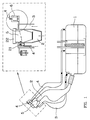
- the tank 1 of a motor vehicle comprises a filling pipe 2 provided with a closable mouth 5, a degassing pipe 3 connected to the mouth 5 and a vent pipe 4, a first part of which is also connected to the mouth 5 and a second connects this mouth to the atmosphere directly or via a recovery canister (not shown).
- the usual positioning of the safety valve 6 according to the invention is shown (shown diagrammatically).
- the second part of the venting pipe takes up not only the fluids flowing in the first part but also the fluids flowing through the degassing pipe 3 and by the filling pipe 2.
- a valve system 21 which has the function of closing the first part of the venting pipe 4 during the removal of the plug 22 for filling the tank 1.
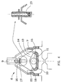
- the safety valve comprises an external enclosure 7 equipped, at its base, with an inlet orifice 8 and, at its upper part, with an outlet orifice 9.
- a fixed circular cup 10 which is kept spaced from the inner wall of the enclosure 7.
- the internal wall 11 of the cup 10 is of conical profile and according to a second embodiment (fig. 3) the internal wall 11 of the cup is planar and provided in its center with a spherical notch 12.
- the enclosure 7 also contains a vertically displaceable element comprising a hollow float 13 (fig. 2) or made of cellular plastic material (fig. 3). In the normal position, the float rests on the edge of the cup 10.
- the base 14 of the float 13 is flat (fig. 2) and according to the second variant (fig. 3) this base 14 is profiled in inverted cone shape.
- a ball 15 of adequate diameter is placed in the cup 10.
- the spherical notch 12 has the function of stabilizing the ball 15 in the center of the cup and of preventing an untimely movement of this ball under the effect of a slight inclination of the enclosure or by inertia, for example during a normal modification of the trajectory of the motor vehicle.
- the float 13 is equipped at its upper part with a needle 16 which, in the upper position of the float, closes the upper orifice 9 of the enclosure 7 by means of a membrane seal 17. As shown in fig. 4 (enlarged part), the needle can optionally be fitted with a pressure relief valve 23.
- venturi 18 is maintained in relation to the volume 19 comprised between the cup 10 and the base of the float 13 by passages formed by notches 20 cut in the edge of the cup 10 and distributed along this edge.
- the safety valve according to the invention allows the vent pipe to fulfill its functions perfectly and closes this pipe securely in any eventuality likely to cause an unwanted exit of liquid fuel .
- the valve safety allows, in normal situation, the evacuation of fuel vapors.
- the depression created in the volume 19 effectively contributes to keeping the float in the low position, notwithstanding in particular its lightness, which makes it possible to achieve very high discharge flow rates without risk of blocking the orifice 9.
- valve allows air to enter the tank to compensate for the fuel consumed.
Landscapes
- Engineering & Computer Science (AREA)
- General Engineering & Computer Science (AREA)
- Mechanical Engineering (AREA)
- Life Sciences & Earth Sciences (AREA)
- Sustainable Development (AREA)
- Sustainable Energy (AREA)
- Chemical & Material Sciences (AREA)
- Combustion & Propulsion (AREA)
- Transportation (AREA)
- Cooling, Air Intake And Gas Exhaust, And Fuel Tank Arrangements In Propulsion Units (AREA)
- Self-Closing Valves And Venting Or Aerating Valves (AREA)
- Float Valves (AREA)
Claims (7)
- Sicherheitsventil für einen die Lüftung gestattenden und den Durchtritt von flüssigem Kraftstoff auf alle Fälle verhindernden Lüftungskanal (4) eines Kraftstoffbehälters (1), umfassend ein geschlossenes Gehäuse (7), das an seinem unteren Teil mit einer mit dem Lüftungskanal (4) verbundenen Eintrittsöffnung (8) und an seinem oberen Teil mit einer gleichfalls mit dem Lüftungskanal verbundenen Austrittsöffnung (9) ausgestattet ist, und bei dem:a) der untere Teil des Gehäuses einen im Abstand von der Innenwand des Gehäuses (7) und von der unteren Eintrittsöffnung (8) gehaltenen ortsfesten inneren runden Teller (10) umfaßt, undb) der Teller von einem vertikal beweglichen Organ gekrönt ist, umfassend einen Schwimmer (13) mit allgemein kegelstumpförmiger oder kugelförmiger Gestalt und eine als Einheit mit dem Schwimmer (13) ausgebildete obere Düsennadel (16), welche die obere Öffnung des Gehäuses in einer oberen Stellung des Organs verschließen kann, wobei Einrichtungen vorgesehen sind, um nach einer Schrägstellung des Gehäuses eine Aufwärtsbewegung des Organs hervorzurufen, dadurch gekennzeichnet, daß daß der Raum zwischen der Innenwand des Gehäuses und dem Teller so geformt ist, daß er eine Venturidüse (18) bildet, die durch mindestens einen Durchlaß (20) derart in Verbindung mit dem zwischen dem Teller (10) und dem Schwimmer (13) des Organs eingeschlossenen Volumen gehalten wird, daß der Durchtritt von Kraftstoffdämpfen in diesem Raum eine Beaufschlagung dieses Volumens mit Unterdruck zur Folge hat.
- Sicherheitsventil nach Anspruch 1, dadurch gekennzeichnet, daß die Einrichtung zum Hervorrufen der Aufwärtsbewegung des Organs nach einer Schrägstellung des Gehäuses von einer Kugel (15) gebildet wird, die in dem Teller (10) mit konischem Innenquerschnitt angeordnet ist, wobei der untere Teil des Schwimmers (13) des beweglichen Organs auf dieser Kugel zur Anlage kommen kann.
- Sicherheitsventil nach Anspruch 1, dadurch gekennzeichnet, daß die Einrichtung zum Hervorrufen der Aufwärtsbewegung des Organs nach einer Schrägstellung des Gehäuses von einer Kugel (15) gebildet wird, die in dem Teller (10) mit ebenem Innenquerschnitt angeordnet ist, welcher in seiner Mitte mit einer runden Vertiefung (12) versehen ist, wobei der untere Teil des Schwimmers (13) des Organs auf dieser Kugel zur Anlage kommen kann und einen Querschnitt in Form eines umgekehrten Kegels aufweist.
- Sicherheitsventil nach Anspruch 1, dadurch gekennzeichnet, daß der Durchlaß (20) durch einen zwischen dem Rand des Tellers (10) und dem unteren Teil des hohlen Fußes des Organs freigehaltenen Raum gebildet wird.
- Sicherheitsventil nach Anspruch 1, dadurch gekennzeichnet, daß die Düsennadel (16) mit einer Membrandichtung (17) ausgestattet ist, so daß der maximale Leckverlust von 0 bis 10 kPa 0,005 l/min beträgt.
- Sicherheitsventil nach Anspruch 1, dadurch gekennzeichnet, daß die Düsennadel (16) mit einem Überdruckventil (23) ausgestattet ist.
- Sicherheitsventil nach Anspruch 1, dadurch gekennzeichnet, daß das Gehäuse (7), der Teller (10) und das Organ aus Kunststoffen gefertigt sind.
Applications Claiming Priority (2)
| Application Number | Priority Date | Filing Date | Title |
|---|---|---|---|
| FR9006016 | 1990-05-11 | ||
| FR9006016A FR2661969B1 (fr) | 1990-05-11 | 1990-05-11 | Clapet de securite notamment pour une canalisation de mise a l'air d'un reservoir a carburant. |
Publications (2)
| Publication Number | Publication Date |
|---|---|
| EP0456313A1 EP0456313A1 (de) | 1991-11-13 |
| EP0456313B1 true EP0456313B1 (de) | 1995-08-09 |
Family
ID=9396598
Family Applications (1)
| Application Number | Title | Priority Date | Filing Date |
|---|---|---|---|
| EP19910201055 Expired - Lifetime EP0456313B1 (de) | 1990-05-11 | 1991-05-03 | Sicherheitsventil, insbesondere für die Entlüftungskanalisation eines Kraftstoffbehälters |
Country Status (4)
| Country | Link |
|---|---|
| EP (1) | EP0456313B1 (de) |
| DE (1) | DE69111883T2 (de) |
| ES (1) | ES2078426T3 (de) |
| FR (1) | FR2661969B1 (de) |
Families Citing this family (1)
| Publication number | Priority date | Publication date | Assignee | Title |
|---|---|---|---|---|
| RU2203190C2 (ru) * | 1997-12-19 | 2003-04-27 | Эргом Материе Пластике СПА | Узел заливочной трубки для топливного бака моторизованного транспортного средства |
Family Cites Families (3)
| Publication number | Priority date | Publication date | Assignee | Title |
|---|---|---|---|---|
| US3765435A (en) * | 1971-11-10 | 1973-10-16 | Gen Motors Corp | Tank vent control unit |
| FR2630686B1 (fr) * | 1988-04-27 | 1991-07-12 | Peugeot | Dispositif de limitation de remplissage d'un reservoir de carburant et vehicule automobile equipe d'un tel dispositif |
| US4917157A (en) * | 1989-02-27 | 1990-04-17 | General Motors Corporation | Vehicle tank vapor vent valve assembly |
-
1990
- 1990-05-11 FR FR9006016A patent/FR2661969B1/fr not_active Expired - Fee Related
-
1991
- 1991-05-03 EP EP19910201055 patent/EP0456313B1/de not_active Expired - Lifetime
- 1991-05-03 ES ES91201055T patent/ES2078426T3/es not_active Expired - Lifetime
- 1991-05-03 DE DE1991611883 patent/DE69111883T2/de not_active Expired - Fee Related
Also Published As
| Publication number | Publication date |
|---|---|
| EP0456313A1 (de) | 1991-11-13 |
| DE69111883D1 (de) | 1995-09-14 |
| FR2661969A1 (fr) | 1991-11-15 |
| ES2078426T3 (es) | 1995-12-16 |
| DE69111883T2 (de) | 1996-05-02 |
| FR2661969B1 (fr) | 1992-10-02 |
Similar Documents
| Publication | Publication Date | Title |
|---|---|---|
| EP1539519B1 (de) | Führung eines kraftstoff-füllstützens mit dichtungs- und sicherheitsvorrichtung | |
| EP1020670B1 (de) | Entlüftungssystem für Flüssigkeitsbehälter | |
| EP1172306B1 (de) | Entlüftungssystem für Flüssigkeitstank | |
| FR2774951A1 (fr) | Reservoir a carburant muni d'un systeme d'evacuation des gaz | |
| FR2886367A1 (fr) | Clapet pour circuit de mise a l'air d'un reservoir a liquide | |
| EP0943476B1 (de) | Entlüftungskreislauf für Flüssigkeitsbehälter | |
| EP0803671B1 (de) | Sicherheitsventil für eine Entlüftungsleitung eines Flüssigkeitsbehälters | |
| FR2905442A1 (fr) | Clapet pour circuit de mise a l'air d'un reservoir a liquide | |
| EP0921026B1 (de) | Entlüftungsleitung für Flüssigkeitsbehälter | |
| FR2954805A1 (fr) | Clapet pour circuit de mise a l'air d'un reservoir a liquide | |
| EP0456313B1 (de) | Sicherheitsventil, insbesondere für die Entlüftungskanalisation eines Kraftstoffbehälters | |
| US5247958A (en) | Safety valve, especially for a fuel tank vent pipe | |
| EP1064166B1 (de) | Entlüftungsvorrichtung für den kraftstofftank eines kraftfahrzeuges | |
| EP0774372B1 (de) | Verbesserte Tankentlüftungsvorrichtung für Kraftfahrzeugtank und Kraftfahrzeugtank mit dieser Vorrichtung | |
| FR2858785A1 (fr) | Reservoir de carburant muni d'un ensemble de valve destine a reduire la permeation de carburant | |
| EP0277869B1 (de) | Ventil, insbesondere für die Entlüftung von Autobrennstofftanks | |
| FR2886366A1 (fr) | Systeme de mise a l'air de reservoir a liquide | |
| EP1064167B1 (de) | Entlüftungsvorrichtung für den kraftstofftank eines kraftfahrzeuges | |
| FR2886368A1 (fr) | Clapet de securite pour circuit de mise a l'air d'un reservoir a liquide | |
| FR3069197A1 (fr) | Dispositif de ventilation pour un reservoir de liquide de vehicule | |
| FR2905745A1 (fr) | Systeme de mise a l'air de reservoir a liquide. | |
| FR2766134A1 (fr) | Dispositif de mise a l'air libre et de securite pour un reservoir de carburant de vehicule automobile | |
| FR2559233A1 (fr) | Purgeur automatique d'air pour canalisation de liquide sous pression | |
| BE846103A (fr) | Purgeur automatique de gaz | |
| WO2016038259A1 (fr) | Boitier comportant une paroi munie d'une enceinte de protection d'une valve, et systeme comportant un tel boitier |
Legal Events
| Date | Code | Title | Description |
|---|---|---|---|
| PUAI | Public reference made under article 153(3) epc to a published international application that has entered the european phase |
Free format text: ORIGINAL CODE: 0009012 |
|
| AK | Designated contracting states |
Kind code of ref document: A1 Designated state(s): BE DE ES GB IT NL SE |
|
| 17P | Request for examination filed |
Effective date: 19920422 |
|
| 17Q | First examination report despatched |
Effective date: 19931125 |
|
| GRAA | (expected) grant |
Free format text: ORIGINAL CODE: 0009210 |
|
| AK | Designated contracting states |
Kind code of ref document: B1 Designated state(s): BE DE ES GB IT NL SE |
|
| PG25 | Lapsed in a contracting state [announced via postgrant information from national office to epo] |
Ref country code: NL Free format text: LAPSE BECAUSE OF FAILURE TO SUBMIT A TRANSLATION OF THE DESCRIPTION OR TO PAY THE FEE WITHIN THE PRESCRIBED TIME-LIMIT Effective date: 19950809 |
|
| REF | Corresponds to: |
Ref document number: 69111883 Country of ref document: DE Date of ref document: 19950914 |
|
| ITF | It: translation for a ep patent filed | ||
| PG25 | Lapsed in a contracting state [announced via postgrant information from national office to epo] |
Ref country code: SE Effective date: 19951109 |
|
| REG | Reference to a national code |
Ref country code: ES Ref legal event code: FG2A Ref document number: 2078426 Country of ref document: ES Kind code of ref document: T3 |
|
| NLV1 | Nl: lapsed or annulled due to failure to fulfill the requirements of art. 29p and 29m of the patents act | ||
| GBT | Gb: translation of ep patent filed (gb section 77(6)(a)/1977) |
Effective date: 19951127 |
|
| PG25 | Lapsed in a contracting state [announced via postgrant information from national office to epo] |
Ref country code: BE Effective date: 19960531 |
|
| PLBE | No opposition filed within time limit |
Free format text: ORIGINAL CODE: 0009261 |
|
| STAA | Information on the status of an ep patent application or granted ep patent |
Free format text: STATUS: NO OPPOSITION FILED WITHIN TIME LIMIT |
|
| 26N | No opposition filed | ||
| BERE | Be: lapsed |
Owner name: SOC. DE TRANSFORMATION DES MATIERES PLASTIQUES S. Effective date: 19960531 |
|
| PGFP | Annual fee paid to national office [announced via postgrant information from national office to epo] |
Ref country code: ES Payment date: 20010530 Year of fee payment: 11 |
|
| REG | Reference to a national code |
Ref country code: GB Ref legal event code: IF02 |
|
| PG25 | Lapsed in a contracting state [announced via postgrant information from national office to epo] |
Ref country code: ES Free format text: LAPSE BECAUSE OF NON-PAYMENT OF DUE FEES Effective date: 20020504 |
|
| REG | Reference to a national code |
Ref country code: ES Ref legal event code: FD2A Effective date: 20030611 |
|
| PGFP | Annual fee paid to national office [announced via postgrant information from national office to epo] |
Ref country code: GB Payment date: 20040428 Year of fee payment: 14 |
|
| PG25 | Lapsed in a contracting state [announced via postgrant information from national office to epo] |
Ref country code: IT Free format text: LAPSE BECAUSE OF NON-PAYMENT OF DUE FEES Effective date: 20050503 Ref country code: GB Free format text: LAPSE BECAUSE OF NON-PAYMENT OF DUE FEES Effective date: 20050503 |
|
| GBPC | Gb: european patent ceased through non-payment of renewal fee |
Effective date: 20050503 |
|
| PGFP | Annual fee paid to national office [announced via postgrant information from national office to epo] |
Ref country code: DE Payment date: 20070426 Year of fee payment: 17 |
|
| PG25 | Lapsed in a contracting state [announced via postgrant information from national office to epo] |
Ref country code: DE Free format text: LAPSE BECAUSE OF NON-PAYMENT OF DUE FEES Effective date: 20081202 |