EP1064166B1 - Entlüftungsvorrichtung für den kraftstofftank eines kraftfahrzeuges - Google Patents
Entlüftungsvorrichtung für den kraftstofftank eines kraftfahrzeuges Download PDFInfo
- Publication number
- EP1064166B1 EP1064166B1 EP99910440A EP99910440A EP1064166B1 EP 1064166 B1 EP1064166 B1 EP 1064166B1 EP 99910440 A EP99910440 A EP 99910440A EP 99910440 A EP99910440 A EP 99910440A EP 1064166 B1 EP1064166 B1 EP 1064166B1
- Authority
- EP
- European Patent Office
- Prior art keywords
- cup
- fact
- communication
- open air
- valve
- Prior art date
- Legal status (The legal status is an assumption and is not a legal conclusion. Google has not performed a legal analysis and makes no representation as to the accuracy of the status listed.)
- Expired - Lifetime
Links
- 239000002828 fuel tank Substances 0.000 title claims description 7
- 238000013022 venting Methods 0.000 description 13
- 230000000694 effects Effects 0.000 description 7
- 238000007789 sealing Methods 0.000 description 4
- 239000007789 gas Substances 0.000 description 3
- 239000000463 material Substances 0.000 description 3
- 239000000446 fuel Substances 0.000 description 2
- 230000001154 acute effect Effects 0.000 description 1
- 230000001143 conditioned effect Effects 0.000 description 1
- 230000007547 defect Effects 0.000 description 1
- 238000001704 evaporation Methods 0.000 description 1
- 230000008020 evaporation Effects 0.000 description 1
- 238000001914 filtration Methods 0.000 description 1
- 230000005484 gravity Effects 0.000 description 1
- 238000010137 moulding (plastic) Methods 0.000 description 1
- 230000002093 peripheral effect Effects 0.000 description 1
- 238000011084 recovery Methods 0.000 description 1
- 238000005096 rolling process Methods 0.000 description 1
Images
Classifications
-
- B—PERFORMING OPERATIONS; TRANSPORTING
- B60—VEHICLES IN GENERAL
- B60K—ARRANGEMENT OR MOUNTING OF PROPULSION UNITS OR OF TRANSMISSIONS IN VEHICLES; ARRANGEMENT OR MOUNTING OF PLURAL DIVERSE PRIME-MOVERS IN VEHICLES; AUXILIARY DRIVES FOR VEHICLES; INSTRUMENTATION OR DASHBOARDS FOR VEHICLES; ARRANGEMENTS IN CONNECTION WITH COOLING, AIR INTAKE, GAS EXHAUST OR FUEL SUPPLY OF PROPULSION UNITS IN VEHICLES
- B60K15/00—Arrangement in connection with fuel supply of combustion engines or other fuel consuming energy converters, e.g. fuel cells; Mounting or construction of fuel tanks
- B60K15/03—Fuel tanks
- B60K15/035—Fuel tanks characterised by venting means
- B60K15/03519—Valve arrangements in the vent line
-
- F—MECHANICAL ENGINEERING; LIGHTING; HEATING; WEAPONS; BLASTING
- F16—ENGINEERING ELEMENTS AND UNITS; GENERAL MEASURES FOR PRODUCING AND MAINTAINING EFFECTIVE FUNCTIONING OF MACHINES OR INSTALLATIONS; THERMAL INSULATION IN GENERAL
- F16K—VALVES; TAPS; COCKS; ACTUATING-FLOATS; DEVICES FOR VENTING OR AERATING
- F16K17/00—Safety valves; Equalising valves, e.g. pressure relief valves
- F16K17/36—Safety valves; Equalising valves, e.g. pressure relief valves actuated in consequence of extraneous circumstances, e.g. shock, change of position
-
- Y—GENERAL TAGGING OF NEW TECHNOLOGICAL DEVELOPMENTS; GENERAL TAGGING OF CROSS-SECTIONAL TECHNOLOGIES SPANNING OVER SEVERAL SECTIONS OF THE IPC; TECHNICAL SUBJECTS COVERED BY FORMER USPC CROSS-REFERENCE ART COLLECTIONS [XRACs] AND DIGESTS
- Y10—TECHNICAL SUBJECTS COVERED BY FORMER USPC
- Y10T—TECHNICAL SUBJECTS COVERED BY FORMER US CLASSIFICATION
- Y10T137/00—Fluid handling
- Y10T137/0753—Control by change of position or inertia of system
-
- Y—GENERAL TAGGING OF NEW TECHNOLOGICAL DEVELOPMENTS; GENERAL TAGGING OF CROSS-SECTIONAL TECHNOLOGIES SPANNING OVER SEVERAL SECTIONS OF THE IPC; TECHNICAL SUBJECTS COVERED BY FORMER USPC CROSS-REFERENCE ART COLLECTIONS [XRACs] AND DIGESTS
- Y10—TECHNICAL SUBJECTS COVERED BY FORMER USPC
- Y10T—TECHNICAL SUBJECTS COVERED BY FORMER US CLASSIFICATION
- Y10T137/00—Fluid handling
- Y10T137/0753—Control by change of position or inertia of system
- Y10T137/0874—Vent opening or closing on tipping container
-
- Y—GENERAL TAGGING OF NEW TECHNOLOGICAL DEVELOPMENTS; GENERAL TAGGING OF CROSS-SECTIONAL TECHNOLOGIES SPANNING OVER SEVERAL SECTIONS OF THE IPC; TECHNICAL SUBJECTS COVERED BY FORMER USPC CROSS-REFERENCE ART COLLECTIONS [XRACs] AND DIGESTS
- Y10—TECHNICAL SUBJECTS COVERED BY FORMER USPC
- Y10T—TECHNICAL SUBJECTS COVERED BY FORMER US CLASSIFICATION
- Y10T137/00—Fluid handling
- Y10T137/8593—Systems
- Y10T137/86292—System with plural openings, one a gas vent or access opening
- Y10T137/86324—Tank with gas vent and inlet or outlet
Definitions
- the invention relates to a venting device for a motor vehicle fuel tank.
- the invention relates more particularly to a device for venting for a motor vehicle fuel tank, of the type in which a valve is provided with a counterweight which is arranged in a chamber into which an inlet opens connected to the tank and an outlet, and of the type in which, when the vehicle is stationary in a substantially horizontal position, the under the effect of its weight, the valve obstructs the valve, and in which, under the effect of the vibrations generated during the setting running or driving the vehicle, the flyweight causes the opening of the valve and the venting of the tank.
- a device for venting for a motor vehicle fuel tank of the type in which a valve is provided with a counterweight which is arranged in a chamber into which an inlet opens connected to the tank and an outlet
- a counterweight which is arranged in a chamber into which an inlet opens connected to the tank and an outlet
- the flyweight causes the opening of the valve and the venting of the tank.
- the flyweight is generally made in the form of a spherical ball which rolls on a surface concave frusto-conical flared upward arranged on a wall lower horizontal of the valve chamber.
- the center of the surface frustoconical is formed by the orifice which is intended to be closed directly by the ball.
- the ball When the vehicle is stationary in position substantially horizontal, the ball, by simple gravity, rests in the center of the frustoconical surface by which it is supported in a circle.
- the sealing of the obturation produced by the ball is conditioned by the correct geometry on the one hand of the ball and, on the other part, of the frustoconical surface. Indeed, in the event of a geometric defect, the contact between the ball and the frustoconical surface does not take place on the entire length of the theoretical contact circle.
- the object of the invention is therefore to propose a new design of a venting device that can achieve simple and economical way a seal between the tank fuel and open air.
- the invention provides a venting device free for a motor vehicle fuel tank, of the type in which a valve is provided with a counterweight which is arranged in a room into which an inlet opening connected to the tank and an outlet, and of the type in which, when the vehicle is stationary in a substantially horizontal position, the counterweight causes, under the effect of its weight, the obturation of the valve, and in which, under the effect of vibrations generated during start-up or the rolling of the vehicle, the counterweight causes the opening of the valve and the venting of the tank, characterized in that the counterweight is supported on a concave upper face of a cup of which a lower face comprises sealing means which are capable of cooperating with a seat formed in a valve body to close one of the valve orifices when the cup is maintained in a closed position by the counterweight in position of stable equilibrium at the bottom of the upper concave surface, and in this that when the flyweight is moved from its stable equilibrium position by vibrations, it causes the cup to tip over so as to interrupt the
- vehicle fuel tanks automobile are generally provided with a venting device free which includes in particular a vent pipe whose a lower portion opens into the tank, at a point top of it, and an upper portion of which is for example connected to a vapor recovery and filtering device.
- a valve is interposed between the lower and upper portions of the pipeline in the open air.
- the venting device compensates for the lower fuel level in the tank allowing the air intake inside the tank so that the prevailing pressure in this one is substantially constant.
- this device in order to avoid any deformation of the tank likely to cause its rupture, this device must also allow the evacuation of gases which would, for example, be compressed due to a temperature rise.
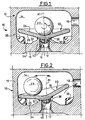
- the venting device 10 which is illustrated in the Figures 1 and 2 partially therefore includes a valve 12 allowing such a closure of the venting circuit when the vehicle is stationary.
- the valve 12 has a chamber 14 which is provided with minus an inlet 16 and an outlet 18.
- the inlet 16, which is arranged through a lower horizontal wall 19 which delimits the chamber 14, is delimited by an internal cylindrical surface 17 of axis A1 and it is for example connected to the fuel tank.
- the outlet 18 opens as for example in a wall side of the chamber 14 or in an upper wall thereof.
- the orifice of outlet 16 is intended to be closed by a cup 20 which is likely to switch between a closed position, illustrated in Figure 1, and an open position, illustrated in Figure 2, under the action a counterweight or ball 22 which is supported under the effect of its weight, on an upper face 24 of the cup 20.
- the cup 20 has substantially a conical shape of A1 axis revolution when the assembly occupies its closed position illustrated in figure 1.
- the upper face 24 of the cup 20 is therefore conical concave, flared upwards at a half-angle at the top ⁇ .
- the face lower 26 of the cup 20 is substantially parallel to the face upper 24 so that the cup 20 has substantially the form of a conical plate of constant thickness.
- the face lower 26 carries, in its center, a boss 28 of which one face lower 30 is flat and horizontal so as to form a span.
- the lower wall 19 of the valve 12 has, substantially in its center, a frustoconical surface 32, of axis A1, which is convex, flared down and raised in relation to the upper face 34 of the wall 18.
- the intersection of the cylindrical surface 17 with the frustoconical surface 32 of the wall lower 18 forms a seat 36 on which is intended to come to rest the inner surface 30 of the bearing surface 20.
- the seat 36 formed at the intersection of two surfaces which have between they an acute angle, can be either in the form of a lip circular, either in the form of an annular chamfer of axis A1.
- the contact between the seat 36 and the bearing surface 30 therefore takes place either in a circle or in a ring.
- the diameter of these two contact surfaces is much less than the transverse dimension of the chamber 14 and the cup 20.
- the counterweight 22 is moved away from its stable equilibrium position, i.e. if it is displaced radially outward relative to the axis A1 of the surface greater than 24 by a distance greater than the radius of the surfaces of contact 30, 36, the weight of ball 22, much greater than that of cup 20, tends to tilt the latter towards a position which is illustrated in FIG. 2 in which the surface of scope 30 is detached from seat 36 except at one point.
- the circulation of gas through valve 12, to the outside or inside of the tank, is then free.
- stops 38 which rise from the upper face 34 of the wall lower 18 of the chamber 14 so as to limit the angle of tilting of the cup 20.
- the stops 38 are intended to cooperate with the radial edge external of the cup 20 and they are arranged at a higher level at the seat 36. More specifically, the stops 38 are arranged in such a way that, when the cup 20 is in the open position, the radius of the upper surface 24 thereof which has the most low slope still has a sufficient slope depending on the direction centripetal so that the flyweight 32 again tends to regain the center of upper surface 24.
- the cup 20 is provided with centering means. which keep it substantially centered along the A1 axis so that when the counterweight 22 is received in the center of the upper face 24, the action of the counterweight 22 on the cup 20 brings it back necessarily in its closed position illustrated in Figure 1. In effect, the thrust exerted by the weight of the counterweight 22 on the cup 20 must then be arranged so as to be inside the circle defined by seat 36.
- the centering means are constituted by a series of fins 40 which extend in relief downwards from the lower surface 30, in the center of it.
- the fins 40 are arranged according to a network of planes vertical perpendicular to each other, the fins 40 also being entirely included within a theoretical envelope surface centered on axis A1.
- the diameter of the spherical envelope is substantially equal to that of the internal cylindrical surface 17 delimiting the orifice 16 so that, when the cup 20 is in the closed position, the fins 40 ensure perfect centering of the cup 20 along the axis A1.
- the fins 40 remain at least partially engaged inside of the orifice 16 but, not having a continuous surface, they do not can oppose the free passage of gases through orifice 16 which can thus be evacuated from the tank to the outside.
- the lateral surface which delimits the chamber 14 presents, in section along a transverse plane perpendicular to the axis A1, a profile corresponding to that of the outer peripheral edge of the cup 20.
- the counterweight 22 preferably has a shape substantially spherical but, unlike the device according to art previous, this sphere does not have to be geometrically perfect.
- the tightness of the valve 12 is determined by the contact between the seat 36 and the bearing surface 30 of the cup 20.
- These parts for example made of plastic molding, can very easily have sufficient geometry to ensure a very good seal.
- the cup 20 can be made of a material rubbery on the one hand perfect the tightness of the contact with the seat and, on the other hand, considerably reduce the noise likely to be caused by successive tilting of the cup.
- the cup 20 can also be produced in a rigid material fully or partially coated with a material rubbery.
- the design of the sealing means of the valve 12 which has just been described can be used in devices for venting incorporating other functions. Especially, this design can be used in venting devices free in which the counterweight 22 also has the function of closing a needle in the event of the vehicle overturning.
Landscapes
- Engineering & Computer Science (AREA)
- Mechanical Engineering (AREA)
- General Engineering & Computer Science (AREA)
- Life Sciences & Earth Sciences (AREA)
- Sustainable Development (AREA)
- Sustainable Energy (AREA)
- Chemical & Material Sciences (AREA)
- Combustion & Propulsion (AREA)
- Transportation (AREA)
- Cooling, Air Intake And Gas Exhaust, And Fuel Tank Arrangements In Propulsion Units (AREA)
- Self-Closing Valves And Venting Or Aerating Valves (AREA)
Claims (8)
- Entlüftungsvorrichtung für den Kraftstofftank eines Kraftfahrzeuges, bei der ein Ventil (12) mit einem in einer Kammer (14), in die eine mit dem Tank verbundene Zuführöffnung und eine Austrittsöffnung einmündet, angeordneten Reguliergewicht (22) ausgerüstet ist und bei der das Reguliergewicht (22), sobald das Fahrzeug in im wesentlichen horizontaler Stellung stillsteht, unter der Wirkung seines Gewichts das Ventil (12) verschließt und beim Anfahren und Rollen des Fahrzeugs aufgrund der erzeugten Schwingungen die Öffnung des Ventils (34) und die Lüftung des Tanks (10) hervorruft, dadurch gekennzeichnet, daß das Reguliergewicht (22) auf einer konkaven Oberseite (24) einer Schale (20) aufliegt, dessen eine Unterseite (26) Verschlußmittel (30), aufweist, die mit einem in einem Ventilkörper befindlichen Sitz (36) zusammenwirken können, der zum Verschließen einer (16) der Öffnungen des Ventils (12) durch das Reguliergewicht (22) in dem Ventilkörper ausgebildet ist, sobald die Schale (20) durch das sich in stabilem Gleichgewicht am Boden der konkaven Oberseite (24) befindliche Reguliergewicht (22) in Schließposition gehalten wird, und dadurch gekennzeichnet, daß, sobald das Reguliergewicht (22) aus seiner stabilen Gleichgewichtsposition durch Schwingungen entfernt wird, ein Kippen der Schale (20) hervorgerufen wird, so daß das Zusammenwirken der Verschlußmittel (30) mit dem Sitz (36) unterbrochen und die Öffnung der Ventils (12) bewirkt wird.
- Entlüftungsvorrichtung nach Anspruch 1, dadurch gekennzeichnet, daß die Schale (20) im wesentlichen eine konische Form mit axialer Achse (A1) aufweist.
- Entlüftungsvorrichtung nach Anspruch 2, dadurch gekennzeichnet, daß die Unterseite (26) der Schale (20) eine ringförmige ebene Auflagefläche (30) aufweist, die in Schließstellung der Schale mit einem ringförmigen Sitz (36) zusammenwirkt, der um eine der in der unteren horizontalen Wand (19) der Kammer (14) angeordneten Öffnungen (16) ausgebildet ist.
- Entlüftungsvorrichtung nach Anspruch 3, dadurch gekennzeichnet, daß der Sitz (36) in Bezug auf eine Oberseite (34) der unteren Wand (19) der Kammer (14) emporgehoben ist .
- Entlüftungsvorrichtung nach Anspruch 4, dadurch gekennzeichnet, daß der Sitz (36) durch den Schnitt einer zylindrischen, vertikalen, die zu verschließende Öffnung (16) abgrenzende Innenfläche (37) mit einer konvexen kegelstumpfartigen nach oben gerichteten Fläche (32), welche koaxial zur zylindrischen Fläche (17) verläuft und sich oberhalb der Oberseite (34) der Innenwand (19) der Kammer (14) erstreckt, gebildet wird.
- Entlüftungsvorrichtung nach irgendeinem der vorangehenden Ansprüche, dadurch gekennzeichnet, daß die Schale (20) einen Zentrierer (40) aufweist, der sich nach unten durch die zu verschließende Öffnung (16) erstreckt und der, zumindest wenn die Schale (20) sich in Schließposition befindet, mit einem Rand der Öffnung (16) zusammenwirkt, um die Schale (20) zu zentrieren.
- Entlüftungsvorrichtung nach Anspruch 6 kombiniert mit dem Anspruch 3, dadurch gekennzeichnet, daß der Zentrierer (40) sich zum Zentrum der ringförmigen Auflagefläche (30) erstreckt.
- Entlüftungsvorrichtung nach irgendeinem der vorangehenden Ansprüche, dadurch gekennzeichnet, daß die Kammer (14) Anschlagmittel (38) aufweist, welche den Kippwinkel der Schale (20) begrenzen.
Applications Claiming Priority (3)
| Application Number | Priority Date | Filing Date | Title |
|---|---|---|---|
| FR9804019 | 1998-03-27 | ||
| FR9804019A FR2776576B1 (fr) | 1998-03-27 | 1998-03-27 | Dispositif de mise a l'air libre pour un reservoir de carburant de vehicule automobile |
| PCT/FR1999/000710 WO1999050086A1 (fr) | 1998-03-27 | 1999-03-26 | Dispositif de mise a l'air libre pour un reservoir de carburant de vehicule automobile |
Publications (2)
| Publication Number | Publication Date |
|---|---|
| EP1064166A1 EP1064166A1 (de) | 2001-01-03 |
| EP1064166B1 true EP1064166B1 (de) | 2002-06-19 |
Family
ID=9524724
Family Applications (1)
| Application Number | Title | Priority Date | Filing Date |
|---|---|---|---|
| EP99910440A Expired - Lifetime EP1064166B1 (de) | 1998-03-27 | 1999-03-26 | Entlüftungsvorrichtung für den kraftstofftank eines kraftfahrzeuges |
Country Status (6)
| Country | Link |
|---|---|
| US (1) | US6289916B1 (de) |
| EP (1) | EP1064166B1 (de) |
| DE (1) | DE69901888T2 (de) |
| ES (1) | ES2178403T3 (de) |
| FR (1) | FR2776576B1 (de) |
| WO (1) | WO1999050086A1 (de) |
Families Citing this family (9)
| Publication number | Priority date | Publication date | Assignee | Title |
|---|---|---|---|---|
| FR2776577B1 (fr) * | 1998-03-27 | 2000-06-16 | Journee Paul Sa | Dispositif de mise a l'air libre pour un reservoir de carburant de vehicule automobile |
| US6668876B2 (en) * | 2001-06-14 | 2003-12-30 | Siemens Vdo Automotive, Incorporated | Method for fuel vapor pressure management |
| US6953027B2 (en) * | 2003-03-07 | 2005-10-11 | Siemens Vdo Automotive Inc. | Flow-through diaphragm for a fuel vapor pressure management apparatus |
| US7011077B2 (en) * | 2003-03-07 | 2006-03-14 | Siemens Vdo Automotive, Inc. | Fuel system and method for managing fuel vapor pressure with a flow-through diaphragm |
| JP2005067281A (ja) * | 2003-08-20 | 2005-03-17 | Toshiba Corp | 距離検出装置、エアバッグ制御装置および距離検出方法 |
| US7124853B1 (en) * | 2004-04-20 | 2006-10-24 | Kole Jr James S | Multiwheeled modular rigid frame vehicle |
| GB0421405D0 (en) * | 2004-09-27 | 2004-10-27 | Edwards Vincent | Gravity lock valve |
| NZ542610A (en) | 2004-09-27 | 2007-04-27 | Autocraft Engineering 1991 Ltd | Gravity actuated hydraulic valve |
| DE102011013959A1 (de) | 2011-03-14 | 2012-09-20 | Kautex Textron Gmbh & Co. Kg | Druckausgleichsventil für Kraftstoff- oder Nebenflüssigkeitsbehälter an einem KFZ |
Family Cites Families (5)
| Publication number | Priority date | Publication date | Assignee | Title |
|---|---|---|---|---|
| US4756328A (en) * | 1987-04-16 | 1988-07-12 | General Motors Corporation | Fuel tank protection valve |
| US5666989A (en) * | 1994-11-08 | 1997-09-16 | Stant Manufacturing Inc. | Tank venting control assembly |
| US5518018A (en) * | 1994-11-14 | 1996-05-21 | Stant Manufacturing Inc. | Fuel tank venting control assembly |
| US5687778A (en) * | 1995-05-01 | 1997-11-18 | Stant Manufacturing Inc. | Dual valve tank venting system |
| FR2740402B1 (fr) | 1995-10-30 | 1997-11-28 | Journee Paul Sa | Reservoir de carburant de vehicule automobile muni d'un dispositif de mise a l'air libre perfectionne et dispositif de mise a l'air libre perfectionne |
-
1998
- 1998-03-27 FR FR9804019A patent/FR2776576B1/fr not_active Expired - Fee Related
-
1999
- 1999-03-26 EP EP99910440A patent/EP1064166B1/de not_active Expired - Lifetime
- 1999-03-26 US US09/647,074 patent/US6289916B1/en not_active Expired - Fee Related
- 1999-03-26 DE DE69901888T patent/DE69901888T2/de not_active Expired - Lifetime
- 1999-03-26 WO PCT/FR1999/000710 patent/WO1999050086A1/fr not_active Ceased
- 1999-03-26 ES ES99910440T patent/ES2178403T3/es not_active Expired - Lifetime
Also Published As
| Publication number | Publication date |
|---|---|
| DE69901888D1 (de) | 2002-07-25 |
| US6289916B1 (en) | 2001-09-18 |
| EP1064166A1 (de) | 2001-01-03 |
| WO1999050086A1 (fr) | 1999-10-07 |
| DE69901888T2 (de) | 2002-11-07 |
| ES2178403T3 (es) | 2002-12-16 |
| FR2776576A1 (fr) | 1999-10-01 |
| FR2776576B1 (fr) | 2000-06-16 |
Similar Documents
| Publication | Publication Date | Title |
|---|---|---|
| EP1079984B1 (de) | Entlüftungsvorrichtung eines kraftstofftanks eines kraftfahrzeuges | |
| EP0254631B1 (de) | Entlüftungsvorrichtung für Brennstofftank | |
| EP1064166B1 (de) | Entlüftungsvorrichtung für den kraftstofftank eines kraftfahrzeuges | |
| FR2733467A1 (fr) | Ensemble a clapet pour reservoir de carburant | |
| FR2886367A1 (fr) | Clapet pour circuit de mise a l'air d'un reservoir a liquide | |
| FR2811648A1 (fr) | Systeme de mise a l'air d'un reservoir a liquide | |
| FR2896568A1 (fr) | Dispositif pour circuit de mise a l'air d'un reservoir a liquide et clapet integrant ledit dispositif | |
| FR2877650A1 (fr) | Dispositif de ventilation de reservoir | |
| FR2905442A1 (fr) | Clapet pour circuit de mise a l'air d'un reservoir a liquide | |
| EP0774372B1 (de) | Verbesserte Tankentlüftungsvorrichtung für Kraftfahrzeugtank und Kraftfahrzeugtank mit dieser Vorrichtung | |
| EP0459866B1 (de) | Einrichtung für den Belüftungskreislauf eines Kraftstofftanks | |
| EP1064167B1 (de) | Entlüftungsvorrichtung für den kraftstofftank eines kraftfahrzeuges | |
| EP0277869B1 (de) | Ventil, insbesondere für die Entlüftung von Autobrennstofftanks | |
| EP0976597B1 (de) | Ventil für den Kraftstofftank eines Kraftfahrzeuges | |
| FR2766134A1 (fr) | Dispositif de mise a l'air libre et de securite pour un reservoir de carburant de vehicule automobile | |
| EP0749860B1 (de) | Verbesserte Kraftstoffzufuhr-Einrichtung in einem Fahrzeugtank | |
| FR2886368A1 (fr) | Clapet de securite pour circuit de mise a l'air d'un reservoir a liquide | |
| FR3069195A1 (fr) | Dispositif de ventilation pour un reservoir de liquide de vehicule. | |
| FR2669864A1 (fr) | Clapet de ventilation pour un reservoir de carburant d'un vehicule. | |
| EP0015187B1 (de) | Verschluss für Kohlenwasserstoff- oder ähnlichen Flüssigkeits behälter | |
| EP0456313B1 (de) | Sicherheitsventil, insbesondere für die Entlüftungskanalisation eines Kraftstoffbehälters | |
| EP2861105B1 (de) | Doppelventil für einen auslaufgeschützten trinkbecher und entsprechender becher | |
| EP0516528B1 (de) | Sicherheitsventil für den Entlüftungskreislauf eines Kfz-Kraftstoffbehälters | |
| BE1007401A6 (fr) | Dispositif de bouchage d'une cuve, bouchon adapte et cuve equipee en consequence. | |
| FR2774636A1 (fr) | Dispositif de mise a l'air libre d'un reservoir de carburant de vehicule automobile |
Legal Events
| Date | Code | Title | Description |
|---|---|---|---|
| PUAI | Public reference made under article 153(3) epc to a published international application that has entered the european phase |
Free format text: ORIGINAL CODE: 0009012 |
|
| 17P | Request for examination filed |
Effective date: 20001008 |
|
| AK | Designated contracting states |
Kind code of ref document: A1 Designated state(s): DE ES FR GB IT |
|
| GRAG | Despatch of communication of intention to grant |
Free format text: ORIGINAL CODE: EPIDOS AGRA |
|
| 17Q | First examination report despatched |
Effective date: 20010615 |
|
| GRAG | Despatch of communication of intention to grant |
Free format text: ORIGINAL CODE: EPIDOS AGRA |
|
| GRAH | Despatch of communication of intention to grant a patent |
Free format text: ORIGINAL CODE: EPIDOS IGRA |
|
| GRAH | Despatch of communication of intention to grant a patent |
Free format text: ORIGINAL CODE: EPIDOS IGRA |
|
| GRAA | (expected) grant |
Free format text: ORIGINAL CODE: 0009210 |
|
| AK | Designated contracting states |
Kind code of ref document: B1 Designated state(s): DE ES FR GB IT |
|
| REG | Reference to a national code |
Ref country code: GB Ref legal event code: FG4D Free format text: NOT ENGLISH |
|
| REF | Corresponds to: |
Ref document number: 69901888 Country of ref document: DE Date of ref document: 20020725 |
|
| GBT | Gb: translation of ep patent filed (gb section 77(6)(a)/1977) |
Effective date: 20020910 |
|
| REG | Reference to a national code |
Ref country code: ES Ref legal event code: FG2A Ref document number: 2178403 Country of ref document: ES Kind code of ref document: T3 |
|
| PLBE | No opposition filed within time limit |
Free format text: ORIGINAL CODE: 0009261 |
|
| STAA | Information on the status of an ep patent application or granted ep patent |
Free format text: STATUS: NO OPPOSITION FILED WITHIN TIME LIMIT |
|
| 26N | No opposition filed |
Effective date: 20030320 |
|
| PGFP | Annual fee paid to national office [announced via postgrant information from national office to epo] |
Ref country code: ES Payment date: 20090326 Year of fee payment: 11 |
|
| PGFP | Annual fee paid to national office [announced via postgrant information from national office to epo] |
Ref country code: IT Payment date: 20090330 Year of fee payment: 11 |
|
| PGFP | Annual fee paid to national office [announced via postgrant information from national office to epo] |
Ref country code: GB Payment date: 20090403 Year of fee payment: 11 |
|
| GBPC | Gb: european patent ceased through non-payment of renewal fee |
Effective date: 20100326 |
|
| PG25 | Lapsed in a contracting state [announced via postgrant information from national office to epo] |
Ref country code: GB Free format text: LAPSE BECAUSE OF NON-PAYMENT OF DUE FEES Effective date: 20100326 Ref country code: IT Free format text: LAPSE BECAUSE OF NON-PAYMENT OF DUE FEES Effective date: 20100326 |
|
| REG | Reference to a national code |
Ref country code: ES Ref legal event code: FD2A Effective date: 20110419 |
|
| PGFP | Annual fee paid to national office [announced via postgrant information from national office to epo] |
Ref country code: FR Payment date: 20110331 Year of fee payment: 13 |
|
| PG25 | Lapsed in a contracting state [announced via postgrant information from national office to epo] |
Ref country code: ES Free format text: LAPSE BECAUSE OF NON-PAYMENT OF DUE FEES Effective date: 20110404 |
|
| PGFP | Annual fee paid to national office [announced via postgrant information from national office to epo] |
Ref country code: DE Payment date: 20110329 Year of fee payment: 13 |
|
| PG25 | Lapsed in a contracting state [announced via postgrant information from national office to epo] |
Ref country code: ES Free format text: LAPSE BECAUSE OF NON-PAYMENT OF DUE FEES Effective date: 20100327 |
|
| REG | Reference to a national code |
Ref country code: FR Ref legal event code: ST Effective date: 20121130 |
|
| REG | Reference to a national code |
Ref country code: DE Ref legal event code: R119 Ref document number: 69901888 Country of ref document: DE Effective date: 20121002 |
|
| PG25 | Lapsed in a contracting state [announced via postgrant information from national office to epo] |
Ref country code: FR Free format text: LAPSE BECAUSE OF NON-PAYMENT OF DUE FEES Effective date: 20120402 |
|
| PG25 | Lapsed in a contracting state [announced via postgrant information from national office to epo] |
Ref country code: DE Free format text: LAPSE BECAUSE OF NON-PAYMENT OF DUE FEES Effective date: 20121002 |