EP0456464B1 - Changeur automatique pour disques numériques - Google Patents
Changeur automatique pour disques numériques Download PDFInfo
- Publication number
- EP0456464B1 EP0456464B1 EP91304110A EP91304110A EP0456464B1 EP 0456464 B1 EP0456464 B1 EP 0456464B1 EP 91304110 A EP91304110 A EP 91304110A EP 91304110 A EP91304110 A EP 91304110A EP 0456464 B1 EP0456464 B1 EP 0456464B1
- Authority
- EP
- European Patent Office
- Prior art keywords
- station
- record
- playing
- digital disc
- arm
- Prior art date
- Legal status (The legal status is an assumption and is not a legal conclusion. Google has not performed a legal analysis and makes no representation as to the accuracy of the status listed.)
- Expired - Lifetime
Links
- 230000007246 mechanism Effects 0.000 claims description 37
- 125000004122 cyclic group Chemical group 0.000 claims description 3
- 230000003287 optical effect Effects 0.000 claims description 3
- 230000001939 inductive effect Effects 0.000 claims 1
- 230000000717 retained effect Effects 0.000 description 9
- 230000006835 compression Effects 0.000 description 5
- 238000007906 compression Methods 0.000 description 5
- 230000002457 bidirectional effect Effects 0.000 description 4
- 230000009471 action Effects 0.000 description 2
- 230000008859 change Effects 0.000 description 2
- 230000008901 benefit Effects 0.000 description 1
- 230000000994 depressogenic effect Effects 0.000 description 1
- 239000000428 dust Substances 0.000 description 1
- 230000000977 initiatory effect Effects 0.000 description 1
- 239000000696 magnetic material Substances 0.000 description 1
- 230000005389 magnetism Effects 0.000 description 1
- 238000004519 manufacturing process Methods 0.000 description 1
- 239000000463 material Substances 0.000 description 1
- 238000000034 method Methods 0.000 description 1
- 230000008569 process Effects 0.000 description 1
- 230000004044 response Effects 0.000 description 1
- 230000007704 transition Effects 0.000 description 1
Images




Classifications
-
- G—PHYSICS
- G11—INFORMATION STORAGE
- G11B—INFORMATION STORAGE BASED ON RELATIVE MOVEMENT BETWEEN RECORD CARRIER AND TRANSDUCER
- G11B19/00—Driving, starting, stopping record carriers not specifically of filamentary or web form, or of supports therefor; Control thereof; Control of operating function ; Driving both disc and head
-
- G—PHYSICS
- G11—INFORMATION STORAGE
- G11B—INFORMATION STORAGE BASED ON RELATIVE MOVEMENT BETWEEN RECORD CARRIER AND TRANSDUCER
- G11B17/00—Guiding record carriers not specifically of filamentary or web form, or of supports therefor
- G11B17/02—Details
- G11B17/04—Feeding or guiding single record carrier to or from transducer unit
- G11B17/05—Feeding or guiding single record carrier to or from transducer unit specially adapted for discs not contained within cartridges
-
- A—HUMAN NECESSITIES
- A44—HABERDASHERY; JEWELLERY
- A44B—BUTTONS, PINS, BUCKLES, SLIDE FASTENERS, OR THE LIKE
- A44B19/00—Slide fasteners
- A44B19/42—Making by processes not fully provided for in one other class, e.g. B21D53/50, B21F45/18, B22D17/16, B29D5/00
- A44B19/60—Applying end stops upon stringer tapes
-
- G—PHYSICS
- G11—INFORMATION STORAGE
- G11B—INFORMATION STORAGE BASED ON RELATIVE MOVEMENT BETWEEN RECORD CARRIER AND TRANSDUCER
- G11B17/00—Guiding record carriers not specifically of filamentary or web form, or of supports therefor
- G11B17/08—Guiding record carriers not specifically of filamentary or web form, or of supports therefor from consecutive-access magazine of disc records
-
- Y—GENERAL TAGGING OF NEW TECHNOLOGICAL DEVELOPMENTS; GENERAL TAGGING OF CROSS-SECTIONAL TECHNOLOGIES SPANNING OVER SEVERAL SECTIONS OF THE IPC; TECHNICAL SUBJECTS COVERED BY FORMER USPC CROSS-REFERENCE ART COLLECTIONS [XRACs] AND DIGESTS
- Y10—TECHNICAL SUBJECTS COVERED BY FORMER USPC
- Y10T—TECHNICAL SUBJECTS COVERED BY FORMER US CLASSIFICATION
- Y10T29/00—Metal working
- Y10T29/49—Method of mechanical manufacture
- Y10T29/49782—Method of mechanical manufacture of a slide fastener
-
- Y—GENERAL TAGGING OF NEW TECHNOLOGICAL DEVELOPMENTS; GENERAL TAGGING OF CROSS-SECTIONAL TECHNOLOGIES SPANNING OVER SEVERAL SECTIONS OF THE IPC; TECHNICAL SUBJECTS COVERED BY FORMER USPC CROSS-REFERENCE ART COLLECTIONS [XRACs] AND DIGESTS
- Y10—TECHNICAL SUBJECTS COVERED BY FORMER USPC
- Y10T—TECHNICAL SUBJECTS COVERED BY FORMER US CLASSIFICATION
- Y10T29/00—Metal working
- Y10T29/53—Means to assemble or disassemble
- Y10T29/53291—Slide fastener
- Y10T29/53296—Means to assemble stop onto stringer
Definitions
- This invention relates generally to digital record changers capable of reading from or writing on records and, more particularly, to digital record changers capable of playing back music and video information.
- Record changers capable of automatically playing a plurality of digital records are known.
- One type of such known changer utilizes cartridges that can each receive a plurality of recorded discs. A cartridge is loaded with discs and inserted into the changer and the records are sequentially played in any desired order.
- a carousel that is loaded with a plurality of records is employed to position individual ones of the records sequentially in a position over a play mechanism. Once the record is in position, the play mechanism is raised from below the carousel and raises the record from the carousel to a playing position where the record is played.
- Such carousels may be accessible from the top of the changer, for example, by opening a dust cover, or may be located in a movable drawer or tray.
- Other types of record changers utilize a plurality of individual trays that extend and retract like drawers and each receives a single record to be played in a selected order. Still other changers utilize such a single record tray for single play and a cartridge for playing multiple discs.
- GB-A-1534057 describes an automatic changer for disc records having a load station, a record/playback station and an unload station arranged in a linear path, with a picker mechanism capable of transferring disc records from the load station to the record/playback station and from the record/playback station to the unload station.
- the invention provides a digital disc record changer comprising three stations: a loading station, a playing station and a discard station, and a transporting means for transporting digital disc records from the loading station to the playing station and from the playing station to the discard station.
- the loading station is a record loading station for receiving a digital disc record to be played.
- the playing station is for sequentially playing digital disc records delivered thereto from the loading station.
- the discard station is for receiving a digital disc record that has been played at the playing station.
- the transporting means comprises means for sequentially:
- the transporting means comprises driving and driven members in frictional engagement with each other to form a friction clutch
- the raising and lowering means comprises cam means whereby relative movement between the driving and driven members is translated by the cam means into a raising and lowering of the transporting means.
- the transporting means moves in a single direction around a cyclic path from the loading station to the playing station to the discard station and then back to the loading station to pick up another digital disc record for play.
- the unidirectional motion eliminates the need for a bidirectional motor and simplifies the control electronics as well as the registering and stopping mechanism; however, bidirectional drive may be used, for example in situations where it is desired to change the relative positions of the three stations.
- the three stations may be arranged in a linear pattern and a bidirectional linear transport used to transport the records between stations.
- the records may be transported between stations in an arcuate bidirectional motion by a reciprocating pivoting transport member similar in motion to an automobile windscreen wiper arm.
- the transporting means comprises a robot arm which includes a pick-up head for picking up individual records.
- the loading station preferably comprises a spindle for receiving either one record or a stack of two or more records.
- a robot arm that includes a pick-up head for picking up the records is used to engage the top record in a stack at the loading position through the center hole in the record and transport it to the play station where it is lowered by the arm into play position.
- the pick-up head in the robot arm applies pressure to the top of the record and is freely rotatable and maintains the record in frictional engagement with a drive mechanism that rotates it during play.
- the robot arm carries the record to the discard station and places it over another spindle where records that have been played are stacked.
- a robot arm preferably pivots about an axis that is equidistant from the loading, play and discard stations so that a simple circular motion of the robot arm may be achieved.
- the robot arm is driven via a clutch mechanism that permits relative motion between the drive motor and the arm.
- the arm is registered at its various stations by posts or other stops located on the base of the changer to eliminate the need for a precision drive mechanism for the arm.
- the robot arm rotates in a single direction from the loading station to the play station to the discard station and then back to the loading station to pick up another record for play.
- a rotary table or carousel is used in place of the robot arm to transport the records to the playing station for playing and away from the playing station after play has been completed.
- the carousel employs a plurality of record-receiving locations or recesses for receiving records to be played. Each time a new record is to be played, the carousel is raised and rotated to place the record to be played over the reading head at the playing station, while any record that has just been played is simultaneously raised and moved away from the reading head. Once a new record to be played has been positioned over the reading head, the carousel is lowered to place the record into playing position.
- a vertically reciprocable record hold-down arm descends, with a rotatable retaining head contacting the center of the record at the playing position to centralize the record and to exert a downward force on the record to bring it into frictional engagement with the playing mechanism.
- the carousel is preferably driven by a friction clutch that permits relative movement between the carousel driving motor and the carousel, and the carousel is preferably registered in the playing position by registering stops on the base to eliminate the need of a precision servomotor to drive the carousel.
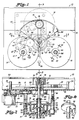
- the changer 10 includes a loading station 12 where one or more discs 14 to be played may be stacked on a spindle 16 and a play station 18 wherein one of the discs 14 is rotated and information encoded on the bottom side of the disc is read by a playing mechanism 20 that includes a movable reading head 19 that includes an optical reader 21; however, other types of readers, for example, a magnetic or other type of reader, can be used depending on the type of disc being read. Also, a writing mechanism capable of writing digital or other information magnetically, optically, thermally or otherwise onto a disc can be used if a writing or recording capability is to be provided.
- the playing mechanism 20 is a standard playing mechanism that is used in compact disc players and is available from various manufacturers, including Sony Corporation and Philips Corporation among others.
- the changer 10 also includes a discard station 22 wherein discs 14 that have been played are stacked about a spindle 24.
- a robot arm 26 that has a pick-up head 28 rotates in the clockwise direction when viewed from the top to pick up a disc 14 from the loading station 12 to the play station 18 wherein the disc 14 is played. After play, the disc is transported by the arm 26 to the discard station 22 where it is discarded. After the played disc has been discarded, the robot arm 26 is again rotated to the loading station 12 where another disc 14 is picked up and transported to the play station.
- a fixed shield 30 and a movable shield 32 that rotates with the robot arm 26 prevent access to the disc 14 during play at the play station 18.
- either of these shields may be transparent to provide a view of the disc 14 during play.
- the shield 32 has a downwardly-extending post 33 that cooperates with three registering posts 34, 36 and 38 that serve to register the robot arm in the play, discard and loading positions, respectively, as will be discussed in a subsequent portion of the specification.
- Three centrally located posts 39 prevent the arm 26 from being lowered when it is positioned between stations.
- the robot arm 26 is driven by a motor 40 via a pair of pulleys 42 and 44 and a drive belt 46.
- a pinion gear 48 is fixed to the pulley 44 and drives a cam and clutch assembly 50 that rotates the robot arm 26 between stations and raising the arm 26 for travel between stations and lowering it at the loading, play and discard stations.
- the drive motor 40 drives the pinion gear 48 via the pulleys 42 and 44 and the belt 46.
- the pinion gear 48 engages a gear 52 on a driving member 54 of the cam and clutch assembly 50.
- the driving member 54 has a downwardly-extending ring-shaped member 56 that engages a driven member 58 that drives a shaft 60 that rotates the robot arm 26.
- a pin 62 extends through the shaft 60 and is keyed into the driven member 58 to provide registration between the driven member 58 and the shaft 60.
- the driven member 58 has a downwardly extending portion 64 that controls the operation of a pair of switch contacts 66 and 68 of a switch 70 as will be subsequently described.
- the driving member 54 also includes a downwardly-extending cam member 72 that engages a cam follower 74 (FIG. 3).
- a pivoted rod 76 is used to exert downward pressure on an upwardly-extending ring-shaped member 78 of the driving member 54, and an extension spring 80 connected at one end to rod 76 and the other end to the base member is used to bias the rod 76 downwardly in order to bias the driving member 54 downwardly to maintain the cam member 72 in contact with the cam follower 74.
- a compression spring 82 that is held in position by a washer 84 and a C-washer 86 that engages a groove in the shaft 60 is used to bias the downwardly-extending ring member 56 of the driving member 54 into frictional engagement with the driven member 58 so that the driven member 58 may be rotated by the driving member 54.
- the driving members 54 and the driven member 58 cooperate to form a slip clutch.
- the shaft 60 is rotatably supported by a pair of bearings 88 and 90 and affixed at the upper end of the shaft 60 to the robot arm 26 by a screw 92.
- the robot arm 26 is positioned relative to the downwardly-extending portion 64 of the driven member so that the portion 64 is positioned to actuate the contacts 66 and 68 of the switch 70 when the arm 26 is at the play station 18.
- Four downwardly-extending posts 94 and screws 96 (FIG. 2) support lower base 97 that supports the cam and clutch assembly 50.
- the cam and clutch assembly 50 serves to rotate the robot arm 26 between the loading station, the play station and the discard station.
- the normal or home position of the arm 26 is the play position at the play station as is shown in FIGS. 1-3.
- the robot arm is rotated clockwise (when viewed from the top) one complete revolution from the play position at the play station, to the discard station, to the loading station and back to the play station.
- the driving member 54 is rotated three complete revolutions, once for each transition between the three stations, while the driven member 58 which is affixed to the robot arm shaft 60 is driven only one revolution from the playing station to the other two stations and back to the play station.
- the cam member serves to raise and lower the robot arm three times, i.e., to raise the robot arm for its travel between stations and to lower it over each of the three stations so that the functions of disc pick up, play and discard may be achieved.
- the disc changing operation will begin from the play station as shown in FIGS. 1-3.
- the robot arm 26 and the driving member 54 and the driven member 58 will be at their bottom most positions.
- the driven member 58 is positioned so that the downwardly-extending portion 64 engages the switch contact 68 thereby opening the switch contacts 66 and 68 and deenergizing the motor 40 so that the robot arm 26 will remain stationary in the position shown in FIGS. 1-3.
- the motor 40 When a changing cycle is initiated, the motor 40 is energized with a momentary pulse of current.
- This momentary pulse of current can be initiated, for example by manually operating a switch on the changer that initiates the changing cycle, or may be generated by electronic means that senses an end-of-disc signal generated by the reading unit 20 when the playing of a disc has been completed and generates the momentary pulse in response thereto.
- the motor 40 rotates the driving member 54 in a clockwise direction when viewed from the top.
- the driving member 54 will rotate and will attempt to rotate the driven member 58 along with it.
- the post 33 on the shield 32 (which rotates along with the arm 26 and the driven member 58) is engaged by the pin 34, the arm 26 and the driven member 58 will be unable to rotate.
- the driving member 54 is positively engaged by the pinion gear 48 which is driven by the motor 40, it will rotate and slippage between the downwardly-extending ring member 56 and the driven member 58 will occur.
- the driving member 54 will rotate while the driven member 58 will remain stationary.
- the cam member 72 will be in contact with the cam follower 74, thus causing the driving member 54, the driven member 58, the robot arm 26 and the shield 32 to raise, and the teeth of the gear 52 of the driving member 54 will ride up the pinion 48.
- the driven member 58 is raised, the downwardly-extending portion 64 will also be raised, thereby allowing the contacts 66 and 68 to close and apply electrical power to the motor 40 for the rest of the changing cycle.
- the closed contacts 66 and 68 will maintain power to the electric motor 40 until the changing cycle is complete and the robot arm 26 is returned to the play station and lowered, whereupon the contacts 66 and 68 will be opened by the downwardly-extending portion 64.
- FIG. 7 shows a developed linearized or flattened out depiction of the cam profile.
- the cam and clutch assembly 50 and the arm 26 are in their lowest positions with the cam follower 74 engaging the cam 72 at its lowest point 100 (left side).
- the cam 72 begins to rotate in a direction which corresponds to a right-to-left movement of the cam 72 shown in FIG. 7.
- the cam follower 74 rides the slope between the point 100 and a point 102 thus lifting the cam and clutch assembly 50 and the arm 26.
- the cam and clutch assembly 50 is lifted sufficiently to allow the closing of the contacts 66 and 68 to maintain power to the motor 40 after the momentary pulse of current has ended.
- the cam profile may take the form of a single straight or curved line segment between points 100 and 104 rather than the two segment profile shown.
- the raising of the arm will proceed until the arm 26 is raised sufficiently to permit the post 33 to clear the post 34.
- the arm 26 is raised sufficiently to allow the post 33 on the shield 32 to clear the post 34 at a point that corresponds to a point 106 on the cam in FIG. 7.
- the driven member 58 being frictionally engaged by the driving member 54, will rotate and cause the arm 26 and the shield 32 to rotate also.
- the cam 72 continues to rotate, it is raised further to its highest point at a point corresponding to point 108 in FIG. 7.
- the arm 26 is maintained at its highest point for a time sufficient to permit the post 33 of the shield 32 to move over the post 34.
- the post 34 passes by the post 33 at a point that corresponds to a point 110 in FIG. 7, and beginning at point 110, the arm 26 is slightly lowered to a height corresponding to point 112, to allow for later engagement of post 33 of the shield 32 with the registering post 36.
- the arm 26 and the shield 32 rotate clockwise when viewed from the top approximately 120° until the post 33 engages the post 36 between the discard station 22 and the loading station 12 (FIG. 12).
- any disc held by the pick-up head 28 will be stacked on the spindle 24.
- the contacts 66 and 68 will still be closed because the downwardly-extending portion 64 is rotated away from the switch 70 and, consequently, the cam 72 will continue to rotate.
- the cam follower will again contact the cam 72 from a point between the point 100 to the point 102 to raise the arm 26 to its dwell position between points 102 and 104.
- the post 33 of the shield 32 will engage the post 36 between the discard station 22 and the loading station 12 and, consequently, the arm will remain stationary over the discard station 22 until the point 106 is again reached, at which point the post 33 is raised high enough to clear the post 36 to permit the arm 26 to rotate. Then the post 33 moves over the post 36, the arm 26 is again lowered to the position corresponding to point 112 in FIG. 7 and the arm continues to rotate until the post 33 of the shield 32 engages the post 38 between the loading station 12 and the play station 18 at the position corresponding to point 114 in FIG. 7 to provide a total of 120° of additional rotation.
- the pick-up head 28 of the arm 26 is positioned over the spindle 16 which contains a stack of discs 14 to be played.
- the arm 26 is again lowered beginning at point 116 so that one of the discs on the spindle may be picked up (FIGS. 17-19).
- the arm 26 continues to be lowered until the cam 72 is positioned with the point 100 being positioned above and spaced from the cam follower 74 after a second complete revolution of the cam 72. At this point, the arm 26 will be positioned as shown in FIG.
- the arm is raised sufficiently to permit the pick-up head 28 to raise a disc over the top of the spindle 16 at the pick-up station 12 (FIG. 19).
- the arm 26 remains above the spindle 16 (FIG. 19) during the dwell time between points 102 and 104.
- the reason for the dwell period is that occasionally two discs may stick together due to a vacuum between the disc or for other reasons.
- the pick-up arm is caused to dwell over the spindle for about a one to two second time period between the points 102 and 104 (or corresponding points if a different cam profile is used) to permit the second disc to drop back onto the spindle 16 during the dwell period in the event that more than one disc has been picked up.
- the dwell between points 102 and 104 on the cam profile may be eliminated and the dwell provided electronically.
- the motor 40 driving the cam and clutch assembly 50 may be momentarily deenergized to stop the cam 72 for the required dwell time, for example, 1-2 seconds.
- the timing of the deenergization of the motor 40 may be controlled by the electronic circuitry that controls the operation of the changer.
- the arm is raised further to the point corresponding to point 106 so that the post 33 of the shield 32 clears the post 38 and the arm is again rotated 120° and lowered at point 112 until the post 33 engages the post 34 and the arm 26 is again positioned over the play station 18.
- the arm 26 is again lowered to position the disc 14 in the play position as the cam rotates from the point 116 back to the point 100. Only at the play station is the downwardly-extending portion 64 of the driven member 58 aligned with the switch 70. Consequently, when the arm 26 is lowered to the play position, the contacts 66 and 68 are opened and the motor 40 is deenergized until the next changing cycle is initiated.
- the electronics associated with the operation of the changer sense the opening of the switch 70 and cause the reading head 19 to sense whether or not a disc 14 is present at the play station 18. If a disc 14 is sensed, play is initiated. If no disc 14 is present, the reading head 19 will remain in an idle mode of operation. Thus, after the last disc has been played, the changer will be in an idle mode.
- FIG. 23 shows the locus of points travelled by the head during a complete changing cycle.
- FIG. 23 shows how the head 28 is raised and lowered three times during the changing cycle, and shows that the raising and lowering action is identical for each of the stations because the raising and lowering action is controlled by the cam 72 which makes one complete revolution as the head travels from station to station.
- the various heights of the arm 26 as it travels between stations are also illustrated in FIG. 10.
- the pick-up head 28 is illustrated in FIG. 8.
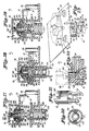
- the pick-up head 28 includes a housing having a larger diameter section 120 and a smaller diameter section 122 as well as the centering projection 124 that has a conical surface 128 and a centering hole 129 formed at the bottom thereof.
- One or more pins 130 having pointed ends 131 are resiliently biased to engage the central hole of a disc.
- the pick-up head 28 cooperates with the spindles at the various ones of the stations to provide different functions.
- the conical portion 128 cooperates with a pin 132 (FIG. 3) that is centered within a drive spindle 134 that is driven by a disc drive motor 135 to center the disc 14 being played on the flange 138.
- the bottom surface 136 (FIG. 8) of the housing of the head 28 exerts a downward pressure provided by a compression spring 148 on the disc 14 during play so that the disc may be frictionally engaged by a flange 138 affixed to the spindle 134 to cause the disc 14 to rotate. Since the head 28 is free to rotate when in the playing position, it will rotate along with the disc 14.
- the pins 130 are resiliently retained within the head 28 by a coiled extension spring 140 that registers the pins 130 in a substantially parallel relationship with each other with a spacing designed to permit them to engage the central hole of a disc 14.
- an elastic band made from rubber or the like, or any other resilient biasing means may be used in place of the spring 140.
- the resiliency of the spring 140 exerts an outward force on the central hole to permit the disc to be lifted, and also permits the lower ends of the pins 130 to be urged inwardly by a ring on the discard spindle 24 to cause the disc to be released, as will be discussed at a subsequent portion of the specification.
- the pick-up head 28 is illustrated in greater detail in FIG. 10 which shows the pick-up head 28 positioned in the play position.
- the centering hole 129 of the centering projection 124 is centered about the pin 132 and serves to center the pick-up head 28 over the spindle 134 and driving flange 138.
- the centering is provided by the pin 132 thus eliminating the need for precise tolerances in the arm 26 and in the arm registering mechanism.
- the disc 14 is centered by a centering section 141 that accurately centers the disc 14 on the flange 138 for rotation by the motor 135.
- the pick-up head 28 is retained within the arm 26 within an aperture 142 that has a diameter larger than the diameter of the body portion 122, but a smaller diameter than the diameter of the body portion 120.
- the aperture 142 serves to retain the pick-up head 28 within the arm 26, but permits a lateral movement of the pick-up head 28 within the arm 26.
- the pick-up head needs to be only generally positioned by the arm 26 over the spindle of each station, with precise positioning being provided by central pins in the various stations that are guided by the conical surface 128 into the centering hole 129 and position the centering projection 124 and consequently the pick-up head 28 precisely over the appropriate spindle.
- a second pin 144 is received in a sleeve portion 145 of the head 28.
- the pin 144 has a head 146 that cooperates with the compression spring 148 to bias the pick-up head downwardly into contact with the shield 32 when the arm 26 is raised.
- the spring 148 When the arm 26 is in the play position as is shown in FIG. 10, and the arm 26 has been lowered with the surface 136 still in contact with the disc 14 the spring 148 is partially compressed. Thus, the spring 148 exerts a downward force on the disc 14 via the surface 136.
- the head 146 of the pin 144 contacts an interior surface of the arm at a point 147 that serves as a pivot point. This causes the disc 14 to be in good frictional engagement with the flange 138 and also provides a pivot point that permits the head 28 to rotate within the end of the arm 26 as the disc 14 is rotated for play by the rotation of the flange 138.
- the spring 148 biases the pick-up head 28 downwardly through the aperture 142 until a surface 150 of the housing of the pick-up head 28 engages an interior surface 152 of the shield 32.
- the arm then is rotated and moved toward the discard station as is illustrated in FIG. 12.
- FIG. 11 shows one of the pins 130 in detail when it engages the center hole of a disc.
- the coiled extension spring 140 engages a reduced diameter section 154 of the pin 130 and exerts an inwardly-directed radial force on the section 154.
- an end 156 of the pin 130 engages an inner surface 158 of the housing supporting the pin 130, and a body portion 157 of the pin 130 engages the lower portion inner surface 158 causing the pin 130 to be substantially vertical and stationary.
- the end of the pin 130 is urged radially inwardly by the central aperture of the disc, thus causing the pin to pivot about a point 160, thus moving the end 156 from the surface 158 as shown in FIG. 11.
- the inwardly-directed radial bias from the spring 140 is then translated by the fulcrum point 160 to an outwardly-directed radial bias at the tip of the pin 130 against the portion 162 of the disc 14 central aperture.
- the arm 26 rotates clockwise when viewed from the top from the play station to the discard station until the downwardly extending post 33 engages the post 36 to generally line up the pick-up head with the spindle 24, as is illustrated in FIG. 12.
- the pins 130 are still in engagement with the central aperture of the disc 14, as is illustrated in FIGS. 12 and 15.
- the spindle 24 is provided with a centering pin 164 that engages the conical surface 128 as the pick-up head 28 is lowered in order precisely to center the pick-up head 28 over the spindle 24 by the pin 164 engaging the hole 129.
- the spindle 24 has a slanted inner surface 166 that engages the pins 130 and moves them radially inwardly against the force of the spring 140 as the pick-up head 28 is lowered.
- the points 131 of the pins 130 are arranged on a circle having a diameter that is smaller than the diameter of the circle defined by the upper portion of the surface 166.
- the conical surfaces of the points 131 ride along the rim of the spindle 24 defined by the surface 166 and are urged inwardly a sufficient amount to cause the disc 14 to be released (FIGS. 13 and 16).
- the head 28 is biased by the rod 76 (FIG. 3) so that the pin 144 is bottomed against the sleeve portion 145 when the surface 180 of the projection 124 of the head 28 contacts a surface 125 of the spindle 24.
- the pins 130 are returned to their substantially vertical position as is shown in FIG. 14, and the empty pick-up head is then transported to the loading station 12.
- the spindle 16 is different than the spindle 24 at the discard station in that it is not rigidly mounted to the base of the changer, but rather moveably retained in a sleeve 170 and biased upwardly by a compression spring 171.
- the spindle 16 is retained within the sleeve 170 by a pair of downwardly depending legs 172 (FIG. 21) that each have a hook portion 174 that engages a lower surface 176 of the sleeve 170.
- the spindle 16 is resiliently biased in an upward position, but may be easily urged downwardly.
- the head 28 As the head 28 is lowered over the spindle 16, it is centered by a centering pin 178 that engages the conical surface 128 of the head 28. As the head is further lowered, the bottom surface 180 (FIG.18) of the centering protrusion 124 of the head 28 contacts a horizontal surface 182 near the top of the spindle 16 and the pin 178 engages the hole 129. Thus, as the head 28 continues its downward motion, the spindle 16 will be pushed downwardly and the downward motion of the head 28 will continue until it reaches the position shown in FIG. 18.
- the head 28 will be lowered until the surface 136 contacts the top one of the discs 14 in the loading station. Once contact is made, the arm 26 will continue to lower, thus compressing the spring 148, and allowing the pin 144 to bottom on the sleeve portion 145 to provide a rigid contact between the arm 26 and the head 28.
- the pins 130 are pushed into the central aperture of the top one of the discs 14 and are being urged inwardly against the bias of the spring 140 by the central aperture of the disc 14 as shown in FIGS. 18 and 22.
- the pins 130 exert an outwardly-directed radial force against the walls of the central aperture of the top disc 14, thus clutching the disc 14 to the head 28 to permit the disc to be picked up as is shown in FIG. 19.
- FIG. 19 shows the pick-up head 28 in a position that corresponds to the dwell position between points 102 and 104 on the cam profile of FIG. 7 or other suitable cam profile as previously discussed.
- the spring 148 has urged the head 28 to its downwardmost position with the surface 150 contacting the surface 152.
- the spring 171 has urged the spindle 16 upwardly to maintain contact with the centering protrusion 124 of the head 28 (FIG. 19). Consequently, if a second disc had been picked up, it would drop back onto the spindle 16 during the time that the head 28 is in the dwell position shown in FIG. 19.
- the arm 26 is again rotated clockwise to the play position as shown in FIGS. 3 and 10.
- the pick-up head 28 will return empty to the play station 18 and the mechanism will remain in an idle mode as stated before.
- the changer 210 utilizes a carousel generally designated by the reference numeral 212 that has a central hub 213 that supports three disc receiving pockets or receptacles 214, 216 and 218.
- a disc playing mechanism 220 has a movable reading head 219 that includes an optical reader 221, but as previously stated, could include another type of reader. Also, a writing mechanism capable of writing digital or other information magnetically, optically, thermally or otherwise onto a disc can be used if a recording capability is desired.
- the disc playing mechanism 220 is similar to the disc mechanism 20 disclosed in the previously described embodiment.
- the changer 210 includes a disc hold-down arm 226 and a retaining head 228.
- a shield 232 is affixed to the portion of the arm 226 containing the head 228 and may be transparent to view the disc on the playing mechanism.
- Each of the receptacles 214, 216 and 218 has an elongated cutout 240, 242 and 244, respectively, formed therein so that the bottom of the disc 14 can be read by the reading head 219 while being rotated by the playing mechanism 220.
- two circular recesses of different sizes, such as the recesses 246 and 248 on the receptacle 218 are provided on each of the receptacles so that two different sized records may be accepted.
- the carousel 212 has a registering blade 233 (FIGS. 25 and 26) that extends downwardly from the central hub 213 and sequentially engages a plurality of registering blocks 234, 236 and 238 (that are analogous to the registering posts 34, 36 and 38 of the first embodiment) as the carousel is rotated so that each of the receptacles 214, 216 and 218 of the carousel 212 is properly positioned over the playing mechanism when in the play position.
- a registering blade 233 is shown, multiple registering blades that simultaneously engage multiple registering blocks may be provided.
- the carousel 212 is driven by a pinion gear (not shown) similar to the pinion gear 48 illustrated in FIG. 2 that engages teeth 252 of a driving member 254 that together with a wheel 297 and a clutch disc 299 forms part of a cam and clutch assembly 250.
- the driving member 254 includes a cam member 272 that engages a cam follower 274 and has a ring shaped member 256 that engages a member 258 that serves to capture the driving member 254 in place; however, other capturing members, for example, a C-washer can be used.
- the driving member 254 is coupled to a tubular shaft 260 that is rotatably supported by a shaft 261 that also supports the arm 226.
- the shaft 260 is step keyed to a boss 259 on the driving member 254.
- a pin 262 keys the member 258 in a non-rotatable relationship with respect to the shaft 261.
- the cam member 272 and the cam follower 274 cooperate to raise and lower the shafts 260 and 261 as the cam 272 is rotated.
- a spring-biased arm 276 (analogous to arm 76 of FIG. 3) exerts a downward biasing force on the rim 278 of the driving member 254.
- a bearing 288 supports the shaft 261 and a bearing 290 supports the tubular shaft 260.
- a screw 292 affixes the shaft 261 to the arm 226.
- a pin 291 passes through a slot 293 in the shaft 261 and through a sleeve 295 that supports the bearing 288 to prevent the shaft 261 from rotating inside the bearing 288 while permitting vertical motion.
- Four downwardly-depending posts 294 support a lower housing that supports the shaft 261, cam follower 274 and switch 270.
- the driving wheel 297 is driven by the shaft 260 and frictionally engages a clutch disc 299 disposed on the bottom of the carousel 212 to form a slip clutch. It should be noted that the carousel could directly contact the driving wheel 297 and thereby also form slip clutch means.
- the carousel 212 is urged for rotation about the shaft 261 by the slip clutch formed by the wheel 297 and the clutch disc 299 or the carousel itself. Also, when the cam 272 is rotated, it moves up and down over the cam follower 274, and raises the carousel 212 and the arm 226 up and down a corresponding amount.
- the cam member 272 is illustrated in FIG. 26 and the cam profile of the cam member 272 is illustrated in FIG. 29 in a flattened out or developed linear presentation similar to that of FIG. 7.
- a disc changing operation it is initiated in a manner similar to that described in conjunction with the robot arm embodiment.
- the carousel 212 and the arm 226 are in their lowermost positions with the cam follower 274 contacting the cam 272 at a point 300 (left side) on the cam profile of FIG. 28.
- the blade 233 is recessed in a slot 400 adjacent the registering block 234 (FIG. 25).
- the carousel 212 and arm 226 are slowly lowered to an intermediate position from a point 310 to a point 312 where the carousel 212 is in a high enough position to permit the blade 233 to stay above a groove 402, but not high enough to clear the registering block 236.
- the cam 272 and carousel 212 continue to rotate until a point 312 is reached where the blade 233 engages the registering block 236, the carousel 212 has been rotated 120° and the next receptacle 216 is in position above the playing mechanism 220.
- the blade 233 is moving down the slot 404 adjacent the registering block 236.
- the carousel 212 and the arm 226 are lowered during the travel of the cam 272 between points 316 and 300 so that the blade 233 may be received by the slot 404, thus completing the changing cycle.
- the cam 272 has rotated a full 360° between points 300 and the carousel has rotated 120°.
- the arm 226 was raised and lowered, but was retained in place over the playing mechanism 220.
- the process is repeated during the next changing cycle and the carousel is positioned with the blade 233 received in the slot 408.
- the changing cycle may be repeated as often as desired.
- the changing cycle of the carousel embodiment is initiated in a manner similar to that disclosed in conjunction with the robot embodiment.
- the pin 274 contacts the point 300 of the cam 272 and the depending portion 264 of the member 258 opens a pair of contacts 266 and 268 of a switch 270 (FIG. 26).
- the motor (not shown) that drives the driven member 254 is deenergized.
- the motor is energized with a momentary pulse of current of sufficient duration to permit the cam 272 to raise sufficiently to cause the depending portion 264 of member 258 (which does not rotate) to raise sufficiently to allow the switch contacts 266 and 268 to close.
- the motor is energized through the closed contacts until the cam makes a complete revolution back to the position shown in FIG. 26, thereby causing the depending portion 264 to be lowered sufficiently to open the contacts 266 and 268.
- the control circuitry causes the reading mechanism 220 to determine whether a disc is present. If a disc is present, it is played, and when the play has been completed, an end-of-disc pulse is generated which causes the control electronics to again generate a momentary pulse of current to initiate another changing cycle. If no disc 14 is sensed, the reading mechanism 220 remains idle.
- the arm 226 is raised from the position illustrated in FIG. 25 to the position illustrated in FIG. 27 and returned to the position illustrated in FIG. 25 upon completion of the changing cycle.
- the disc 14 is retained in engagement with a flange 338 on a motor shaft 334 that is driven by a disc driving motor 335.
- the head 228 is similar to the head 28 in the previous embodiment in that it utilizes a spring 348 to exert a downward bias on the head 228 to retain the disc 14 in place on the flange 338.
- the spring 348 surrounds a pin 344 that has a head 346 and causes the head 346 to engage a contact point 347 on the interior surface of the housing of the arm 226.
- the point 347 serves as a pivot point to permit the head 228 to rotate with the disc 14.
- the head 228 has a centering projection 324 (FIG. 27) that has a conical surface 328 in the end thereof that engages a centering pin 332 extending from the motor shaft.
- the pin 332 engages the conical surface 328 that guides the pin 332 into a centering hole 329 and centers the head 228 over the disc 14.
- the disc 14 is centered by a resiliently mounted centering spindle 333 that is biased upwardly by a low-force compression spring 337.
- the centering spindle 333 engages the central aperture of the disc 14 as the carousel is lowered over the spindle 333 and centers the disc 14 over the driving flange 338.
- the centering spindle is depressed by the spring 348 to a point sufficient to permit the surface 336 of the head 228 to frictionally retain engagement of the disc 14 to the flange 338.
- the arm 226 was retained over the play station 212 by the pin 291 that engaged the slot 293 that permitted vertical motion of the arm 226, but prevented the arm 226 from rotating.
- FIGS. 31 and 32 An alternative way to retain the arm 226 over the play station 212 is illustrated in FIGS. 31 and 32.
- the shield 232 has an extension 450 that has an elongated aperture 452 that engages an upstanding pin 454 that extends upwardly from the base of the changer.
- the aperture 452 and pin 454 are dimensioned to permit the shield 232 to move freely up and down as the arm 226 is raised and lowered, while still preventing the shield 232 and, hence, the arm 226 from rotating.
- the aperture 452 is elongated to accommodate variations in the position of the shield 232 relative to the pin 454 resulting from manufacturing tolerances.
- the post 454 is sufficiently long so that it engages the aperture 454 even when the shield 232 is raised to its uppermost position.
- the arrangement illustrated in FIGS. 31 and 32 has the advantage that it provides more accurate alignment of the arm 226 over the playing mechanism 220 because the post 454 is radially displaced from the center line of the shaft 261 by a relatively long distance.
- any variations in the position of the aperture 452 or the post 454 will result in only minor angular deviations of the arm 226.
- the arm 226 will be less likely to wobble when registered by the post 454 than by the pin 291.
- a registering post 456 that extends upwardly from the base of the changer is provided (FIGS. 31 and 32). The post 456 is located in the vicinity of the playing mechanism 220 and is engaged by the one of the receptacles of the carousel 212 that is positioned over the playing mechanism 220. Only a single post 456 may be provided near the playing mechanism 220 or elsewhere to engage another portion of the carousel 212, or multiple posts engaging the carousel 212 at multiple points may be provided.
- three posts may be equidistantly spaced in the vicinity of each of the receptacles so that each of the three receptacles may be engaged when one of the receptacles is in the play position.
- the height of the post 456 is illustrated in FIG. 32 and is selected so that when the carousel is in its lowermost or intermediate position, the carousel 212 engages the post 456, but when the carousel 212 is raised to its highest position, the post 456 is cleared.
- the heads previously described that were used to hold the discs at the play station utilized a resilient biasing member such as a spring to maintain pressure against the disc 14 while the disc 14 was being rotated for play.
- the retaining friction force on the disc may be exerted magnetically.
- FIG. 30 there is shown a pick-up head 528 that utilizes magnetic disc retainer and is suitable for use in the robot arm embodiment of the invention.
- the function of the head 528 is similar to that of the head 28 (FIG. 8) and analogous components of the two heads will be numbered with like reference numerals, except those in FIG. 30 will be primed.
- the head 528 utilizes a centering member 544 that has a centering projection 124′ that has a conical surface 128′ for centering the head 528 over a centering pin 132′.
- pins 130′ that have points 131′ and are resiliently retained in the head 528 by a coiled extension spring 140′ are provided to engage the central aperture of a disc 14.
- a magnetic head similar to the head 528 may be used in conjunction with a carousel, and in that event, the pins 130′ and the spring 140′ would be eliminated, and the centering member 544 would be modified to cooperate with the centering spindle 333.
- the head 528 does not utilize any resilient biasing mechanism to retain the disc 14 to the flange 138′. Rather, an annular magnet 530 is retained in a spool-like retainer 532 that has a pair or flanges 534 and 536 and a ring 538 that retain the magnet 530 within the end of the arm.
- the ring 538 is integrally molded with the flange 534 and has a plurality of upstanding members 540 that engage apertures 542 in the flange 536 and serve to secure the annular magnet 530 between the flanges 534 and 536.
- the central hole in the annular magnet 530 is selected so that it can receive centering member 544 including the pins 130′ without interference.
- the magnetic retainer 532 containing magnet 530 is received within an aperture 142′ in the shield 32′, and the diameter of the aperture 142′ is greater than the outside diameter of the ring 538 to permit the magnet 530 and the retainer 532 to move laterally within the aperture 142′ to permit the head 528 to be centered by the pin 132′.
- the spacing between the flanges 534 and 536 is chosen so that neither flange will touch the shield 32′ when the head is positioned at a play station. In the play station, the head will be positioned as illustrated in FIG. 30 with the surface 136′ of the flange 534 being in contact with the disc 14.
- the magnetic force of the magnet 530 extends through the flange 534 and the disc 14, both of which are fabricated from non-magnetic material and attracts the flange 138′ which is fabricated from a material that attracts magnetism.
- the attractive force of the magnet 530 exerts a downward force on the flange 534 and the disc 14 and serves to retain the disc 14 frictionally on the flange 138′.
- an upper portion 546 of the centering member 544 contacts an inner surface 547 of the arm (e.g. arm 26 or arm 226) so that the downward bias of the arm is directly translated to the centering projection 124′.
- the arm e.g. 26 or 226) is raised, the flange 536 is engaged by the shield 32′ to raise the head 528 when a disc is being transported.
Landscapes
- Automatic Disk Changers (AREA)
Claims (10)
- Changeur pour disques numériques comprenant :
un poste (12) de chargement de disques pour recevoir horizontalement un disque numérique (14) à jouer ;
un poste (18) de lecture de disques pour jouer successivement les disques numériques (14) transmis horizontalement à celui-ci depuis le poste de chargement (12) ;
un poste d'éjection (22) des disques pour recevoir le disque numérique (14) qui a été joué au niveau du poste (18) de lecture ; et
des moyens de transport (26 ; 212) pour transporter les disques numériques (14) depuis le poste de chargement (12) vers le poste (18) de lecture et depuis le poste (18) de lecture vers le poste d'éjection (22)
caractérisé en ce que
les moyens de transport (26 ; 212) comprennent des moyens pour successivement soulever jusqu'à une position haute un disque numérique (14) à transporter depuis le poste de chargement (12) vers le poste (18) de lecture ; des moyens pour transporter le disque vers le poste de lecture dans cette position haute ; des moyens pour abaisser le disque jusqu'à un niveau où il peut être joué au niveau du poste de lecture ; des moyens pour soulever le disque jusqu'en position haute après avoir été joué ; des moyens pour transporter le disque vers le poste d'éjection dans cette position haute ; et des moyens pour abaisser le disque au niveau du poste d'éjection (22). - Changeur pour disques numériques selon la revendication 1, dans lequel le poste de chargement (12), le poste (18) de lecture et le poste d'éjection (22) sont disposés suivant un chemin cyclique autour d'un axe central, et les moyens de transport (26 ; 212) comprennent des éléments d'entraînement et entraînés (56, 58 ; 297, 299) en prise par friction les uns avec les autres pour former un embrayage à friction, et les moyens de soulèvement et d'abaissement comprennent des moyens à came (72, 74 ; 272, 274) grâce à quoi le déplacement relatif par rotation entre les éléments d'entraînement et entraînés est traduit par les moyens à came en un soulèvement et un abaissement des moyens de transport.
- Changeur pour disques numériques selon la revendication 2, dans lequel les moyens de transport (26 ; 212) comprennent des éléments d'arrêt (34, 36, 38 ; 234, 236, 238) pour entraver le déplacement cyclique de l'élément entraîné (58, 299) lorsque chaque disque (14) qui est transporté se trouve tour à tour au niveau des postes de chargement, de lecture et d'éjection (12, 18, 22), ce qui provoque un déplacement relatif par rotation entre les éléments d'entraînement et entraînés (56, 58 ; 297, 299), et dans lequel les moyens à came (72, 74 ; 272, 274) comprennent une portion de came pour soulever les moyens de transport au-dessus des éléments d'arrêt au début de chaque déplacement d'un disque depuis un poste vers le suivant.
- Changeur pour disques numériques selon l'une quelconque des revendications précédentes, dans lequel le poste (18) de lecture comprend des moyens de centrage (132 ; 332) grâce à quoi, lorsqu'un disque à jouer est abaissé par les moyens de transport (26 ; 212) au niveau du poste de lecture en prise par friction avec un élément d'entraînement rotatif (138 ; 338), il est précisément centré par les moyens de centrage sur l'axe de rotation de l'élément d'entraînement rotatif.
- Changeur pour disques numériques selon l'une quelconque des revendications précédentes, dans lequel le poste de chargement (12) comprend un arbre (16) destiné à recevoir un ou plusieurs disques à jouer ; le poste d'éjection (22) comprend un arbre (24) destiné à recevoir un ou plusieurs disques qui ont été joués ; et les moyens de transport comprennent un bras automatique (26) pourvu de moyens (28) venant en prise avec les disques pour prendre un disque au niveau du poste de chargement, le transmettre au poste (18) de lecture pour le jouer et le libérer au niveau du poste d'éjection après qu'il ait été joué.
- Changeur pour disques numériques selon la revendication 5, dans lequel les moyens (28) venant en prise avec le disque comprennent des moyens (130) pour venir en prise par friction avec l'intérieur d'une ouverture centrale ménagée dans le disque (14) le plus au-dessus, au niveau du poste de chargement (12), lorsque le bras automatique (26) est abaissé au niveau du poste de chargement, et des moyens (131, 166) pour libérer cette prise par friction lorsque le bras automatique est abaissé au niveau du poste d'éjection (22).
- Changeur pour disques numériques selon la revendication 5 ou 6, dans lequel les moyens de transport (26) comprennent des moyens (102-104) pour établir un temps de séjour du bras automatique (26) dans sa position haute ou partiellement haute sur le poste de chargement (12) avant que le déplacement ne se poursuive vers le poste (18) de lecture.
- Changeur pour disques numériques selon l'une quelconque des revendications 1 à 4, dans lequel les moyens de transport comprennent une table (212) pourvue d'emplacements espacés (214, 216, 218) destinés à recevoir des disques sur ceux-ci, et les moyens de soulèvement et d'abaissement agissent pour soulever et abaisser la table et tous les disques (14) portés sur celle-ci au cours du transport des disques depuis le poste de chargement (12) vers le poste (18) de lecture puis vers le poste d'éjection (22).
- Changeur pour disques numériques selon la revendication 8, dans lequel l'abaissement de la table (212) portant un disque (14) sur le poste (18) de lecture entraîne l'abaissement du disque jusque sur un mécanisme d'entraînement (338) et son maintien en place sur le mécanisme d'entraînement par une tête de maintien mobile en rotation (228) d'un bras de retenue de disque (226) susceptible d'être animé d'un mouvement de va-et-vient vertical, qui est constamment positionné sur le poste de lecture.
- Poste de lecture de disques numériques incorporant un changeur pour disques numériques selon l'une quelconque des revendications précédentes, dans lequel le poste (18) de lecture comprend une tête de lecture optique ou magnétique (19) pour lire optiquement ou magnétiquement des données codées numériquement, et susceptibles d'être lues, sur des disques (14) au niveau du poste de lecture ; et comprenant en outre éventuellement une tête d'écriture ou d'enregistrement pour enregistrer des données codées numériquement sur des disques (14) au niveau du poste de lecture.
Applications Claiming Priority (2)
| Application Number | Priority Date | Filing Date | Title |
|---|---|---|---|
| US518475 | 1990-05-09 | ||
| US07/518,475 US5291465A (en) | 1990-05-09 | 1990-05-09 | Automatic changer for digital discs |
Publications (2)
| Publication Number | Publication Date |
|---|---|
| EP0456464A1 EP0456464A1 (fr) | 1991-11-13 |
| EP0456464B1 true EP0456464B1 (fr) | 1995-07-26 |
Family
ID=24064089
Family Applications (1)
| Application Number | Title | Priority Date | Filing Date |
|---|---|---|---|
| EP91304110A Expired - Lifetime EP0456464B1 (fr) | 1990-05-09 | 1991-05-07 | Changeur automatique pour disques numériques |
Country Status (12)
| Country | Link |
|---|---|
| US (1) | US5291465A (fr) |
| EP (1) | EP0456464B1 (fr) |
| JP (1) | JPH0419865A (fr) |
| KR (1) | KR910020685A (fr) |
| CN (1) | CN1027936C (fr) |
| AR (1) | AR244458A1 (fr) |
| AT (1) | ATE125634T1 (fr) |
| BR (1) | BR9101860A (fr) |
| DE (1) | DE69111508T2 (fr) |
| HK (1) | HK182695A (fr) |
| MX (1) | MX174057B (fr) |
| MY (1) | MY106085A (fr) |
Cited By (1)
| Publication number | Priority date | Publication date | Assignee | Title |
|---|---|---|---|---|
| US6259976B1 (en) | 1999-09-25 | 2001-07-10 | Jerome H. Lemelson | Fuzzy logic based emergency flight control with thrust vectoring |
Families Citing this family (20)
| Publication number | Priority date | Publication date | Assignee | Title |
|---|---|---|---|---|
| JPH0421967A (ja) * | 1990-05-15 | 1992-01-24 | Sansui Electric Co Ltd | ディスクプレーヤ |
| JPH0421966A (ja) * | 1990-05-15 | 1992-01-24 | Sansui Electric Co Ltd | ディスクプレーヤのディスクチャック |
| US5335218A (en) * | 1991-05-02 | 1994-08-02 | Sony Corporation | Disc loading transfer mechanism for plural disc changer |
| JPH04353664A (ja) * | 1991-05-30 | 1992-12-08 | Pioneer Electron Corp | ディスクプレーヤ |
| US5541897A (en) * | 1994-06-13 | 1996-07-30 | International Business Machines Corporation | Multi-carousel library with double disk receptacles and single disk retainer |
| US7145841B1 (en) * | 1997-03-13 | 2006-12-05 | David Miller | Programmable self-operating compact disk duplication system |
| US6822932B2 (en) * | 1997-03-13 | 2004-11-23 | David Miller | Programmable self-operating compact disk duplication system |
| US6141298A (en) * | 1997-03-13 | 2000-10-31 | Miller; David | Programmable self-operating compact disk duplication system |
| US6222800B1 (en) | 1997-06-02 | 2001-04-24 | Copy Pro, Inc. | Autoload disk copier system |
| JP2000100127A (ja) * | 1998-09-24 | 2000-04-07 | Pioneer Electronic Corp | ディスクプレーヤ |
| US6802070B2 (en) | 2000-06-09 | 2004-10-05 | Primera Technology, Inc. | Compact disc transporter |
| JP2002074807A (ja) * | 2000-08-29 | 2002-03-15 | Funai Electric Co Ltd | ディスク再生装置 |
| DE10241311A1 (de) * | 2002-09-04 | 2004-03-18 | Deutsche Thomson-Brandt Gmbh | CD-Wechsler |
| JP3988706B2 (ja) * | 2003-09-30 | 2007-10-10 | ティアック株式会社 | ディスク保持機構 |
| TW200623032A (en) * | 2004-12-17 | 2006-07-01 | Lite On It Corp | Method and device for setting sequence of playing disks in multi-disk optical disk drives |
| US7810109B2 (en) * | 2006-08-09 | 2010-10-05 | Primera Technology Inc. | Compact disc picker |
| JP5056127B2 (ja) | 2007-04-05 | 2012-10-24 | セイコーエプソン株式会社 | メディア搬送機構及びそれを備えたメディア処理装置 |
| JP4375425B2 (ja) * | 2007-04-05 | 2009-12-02 | セイコーエプソン株式会社 | メディア搬送機構、それを備えたメディア処理装置、及びメディア搬送方法 |
| TWM385061U (en) * | 2010-03-24 | 2010-07-21 | Acard Technology Corp | Digital surveillance system structure |
| JP2011243237A (ja) * | 2010-05-14 | 2011-12-01 | Nippon Hoso Kyokai <Nhk> | ディスク出し入れ機構及びディスク搬送装置 |
Family Cites Families (28)
| Publication number | Priority date | Publication date | Assignee | Title |
|---|---|---|---|---|
| US2274921A (en) * | 1937-07-15 | 1942-03-03 | Bernice M Filben | Automatic phonograph |
| US2339062A (en) * | 1940-11-04 | 1944-01-11 | Rock Ola Mfg Corp | Phonograph |
| US2557645A (en) * | 1946-09-30 | 1951-06-19 | Fox Joseph | Automatic record-changing phonograph mechanism |
| US2670211A (en) * | 1947-01-08 | 1954-02-23 | Magnavox Co | Record changer |
| US2960340A (en) * | 1955-10-05 | 1960-11-15 | Georg Wiegandt & Sohne | Automatic record changer for phonographs |
| US3009705A (en) * | 1957-10-10 | 1961-11-21 | Harting Elektro W | Mechanism for the preselection of gramophone records |
| US3097850A (en) * | 1960-06-07 | 1963-07-16 | Curci Alfred | Phonograph record-changing apparatus |
| CH386127A (fr) * | 1962-08-24 | 1964-12-31 | Thorens Sa | Changeur de disques automatique |
| US3789160A (en) * | 1971-12-20 | 1974-01-29 | Ibm | Dictation apparatus with disc loading, feeding, and ejecting feature |
| JPS4895211A (fr) * | 1972-03-15 | 1973-12-06 | ||
| IT958864B (it) * | 1972-05-13 | 1973-10-30 | Olivetti & Co Spa | Dispositivo per la sostituzione automatica di una cassetta contenen te un nastro magnetico in una appa recchiatura per la registrazione e o lettura del nastro contenuto in detta cassetta |
| US3976300A (en) * | 1975-03-17 | 1976-08-24 | International Business Machines Corporation | Loader carrier mechanism |
| US4099209A (en) * | 1976-09-10 | 1978-07-04 | Dictaphone Corporation | Electronic control system for multiple cassette record and/or playback apparatus |
| US4071857A (en) * | 1976-09-10 | 1978-01-31 | Dictaphone Corporation | Cassette changer apparatus |
| US4447836A (en) * | 1980-04-28 | 1984-05-08 | Telex Communications, Inc. | Recording apparatus for cassette copying |
| US4665455A (en) * | 1983-01-24 | 1987-05-12 | Modular Robotics | Diskette sequential transport apparatus |
| ATE72712T1 (de) * | 1984-06-06 | 1992-03-15 | Sony Corp | Plattenspeichervorrichtung. |
| US4594042A (en) * | 1984-07-09 | 1986-06-10 | Pitney Bowes Inc. | Device for stacking microcassettes |
| JPS6148163A (ja) * | 1984-08-10 | 1986-03-08 | Mitsubishi Electric Corp | 円盤状記録媒体の連続駆動装置 |
| US4779151A (en) * | 1985-04-08 | 1988-10-18 | Odetics, Inc. | Robotic tape cassette handling system with rotary loading and unloading mechanism |
| JPH0675329B2 (ja) * | 1986-02-18 | 1994-09-21 | ソニー株式会社 | ディスクプレーヤ |
| US4817070A (en) * | 1987-02-12 | 1989-03-28 | Cygnet Systems, Inc. | Information handling system for use with information containing storage discs |
| CN1017574B (zh) * | 1987-02-27 | 1992-07-22 | 三菱电机株式会社 | 盘存储装置 |
| JPH07122949B2 (ja) * | 1987-03-30 | 1995-12-25 | 株式会社東芝 | カセツト装填装置 |
| US4827463A (en) * | 1987-04-07 | 1989-05-02 | Mitsubishi Denki Kabushiki Kaisha | Disc memory device |
| US4815055A (en) * | 1987-04-17 | 1989-03-21 | Access Corporation | Data medium storage and retrieval devices |
| US4903154A (en) * | 1987-06-02 | 1990-02-20 | Costas Dan N | Automatic diskette stack loader |
| US4817071A (en) * | 1988-04-22 | 1989-03-28 | Eastman Kodak Company | Disk-loading station for automated disk library |
-
1990
- 1990-05-09 US US07/518,475 patent/US5291465A/en not_active Expired - Lifetime
- 1990-06-11 JP JP2152522A patent/JPH0419865A/ja active Pending
-
1991
- 1991-05-06 MY MYPI91000759A patent/MY106085A/en unknown
- 1991-05-07 EP EP91304110A patent/EP0456464B1/fr not_active Expired - Lifetime
- 1991-05-07 AT AT91304110T patent/ATE125634T1/de not_active IP Right Cessation
- 1991-05-07 DE DE69111508T patent/DE69111508T2/de not_active Expired - Fee Related
- 1991-05-08 BR BR919101860A patent/BR9101860A/pt not_active Application Discontinuation
- 1991-05-08 CN CN91103088A patent/CN1027936C/zh not_active Expired - Lifetime
- 1991-05-08 KR KR1019910007562A patent/KR910020685A/ko not_active Ceased
- 1991-05-09 AR AR91319655A patent/AR244458A1/es active
- 1991-05-09 MX MX025726A patent/MX174057B/es unknown
-
1995
- 1995-11-30 HK HK182695A patent/HK182695A/en not_active IP Right Cessation
Cited By (1)
| Publication number | Priority date | Publication date | Assignee | Title |
|---|---|---|---|---|
| US6259976B1 (en) | 1999-09-25 | 2001-07-10 | Jerome H. Lemelson | Fuzzy logic based emergency flight control with thrust vectoring |
Also Published As
| Publication number | Publication date |
|---|---|
| MX174057B (es) | 1994-04-18 |
| JPH0419865A (ja) | 1992-01-23 |
| CN1056365A (zh) | 1991-11-20 |
| DE69111508D1 (de) | 1995-08-31 |
| US5291465A (en) | 1994-03-01 |
| KR910020685A (ko) | 1991-12-20 |
| ATE125634T1 (de) | 1995-08-15 |
| AR244458A1 (es) | 1993-10-29 |
| EP0456464A1 (fr) | 1991-11-13 |
| BR9101860A (pt) | 1991-12-17 |
| DE69111508T2 (de) | 1996-04-11 |
| CN1027936C (zh) | 1995-03-15 |
| MY106085A (en) | 1995-03-31 |
| HK182695A (en) | 1995-12-08 |
Similar Documents
| Publication | Publication Date | Title |
|---|---|---|
| US5291465A (en) | Automatic changer for digital discs | |
| US6321649B1 (en) | Compact disc label printer with rotatable picker arm | |
| US5067116A (en) | Automatic disc changer apparatus | |
| US5214628A (en) | Compact disc storage and playing apparatus | |
| US5153862A (en) | Cassette for storing, moving and loading optical storage disk cartridges | |
| EP0263496B1 (fr) | Appareil d'enregistrement et de reproduction | |
| JPH05504862A (ja) | ディスク再生装置 | |
| US4539663A (en) | Disc playing system with continuous playing function | |
| US4996680A (en) | Automatic changing apparatus for a recording medium | |
| US5897153A (en) | Apparatus for removing and/or returning a disk shaped object to and from a disk holder | |
| US4800551A (en) | Method and apparatus for feeding card | |
| US7151718B2 (en) | Media storage system | |
| US4815057A (en) | Multiple-player disc-changer apparatus | |
| US5197056A (en) | Disc record player | |
| GB2266617A (en) | Disc player | |
| US3976301A (en) | Record selector mechanism for a phonograph system | |
| EP0811976B1 (fr) | Appareil pour le stockage, transfert de supports d'information | |
| US20060136950A1 (en) | Appliance with a data carrier disk drive and method of inserting a data carrier in such an appliance | |
| US3872506A (en) | Apparatus for automatically playing back information in cassettes | |
| US2645496A (en) | Automatic phonograph mechanism | |
| US20090039103A1 (en) | Optical disc dispenser for printer or duplicator | |
| US3020050A (en) | Spindle for automatic drop-type phonographs | |
| KR100186264B1 (ko) | 디스크의 로딩 장치 | |
| JPH056600Y2 (fr) | ||
| KR0138353B1 (ko) | 디스크 체인저 |
Legal Events
| Date | Code | Title | Description |
|---|---|---|---|
| PUAI | Public reference made under article 153(3) epc to a published international application that has entered the european phase |
Free format text: ORIGINAL CODE: 0009012 |
|
| AK | Designated contracting states |
Kind code of ref document: A1 Designated state(s): AT DE ES FR GB IT NL |
|
| 17P | Request for examination filed |
Effective date: 19920330 |
|
| 17Q | First examination report despatched |
Effective date: 19940222 |
|
| GRAA | (expected) grant |
Free format text: ORIGINAL CODE: 0009210 |
|
| AK | Designated contracting states |
Kind code of ref document: B1 Designated state(s): AT DE ES FR GB IT NL |
|
| PG25 | Lapsed in a contracting state [announced via postgrant information from national office to epo] |
Ref country code: NL Free format text: LAPSE BECAUSE OF FAILURE TO SUBMIT A TRANSLATION OF THE DESCRIPTION OR TO PAY THE FEE WITHIN THE PRESCRIBED TIME-LIMIT Effective date: 19950726 Ref country code: ES Free format text: THE PATENT HAS BEEN ANNULLED BY A DECISION OF A NATIONAL AUTHORITY Effective date: 19950726 Ref country code: AT Effective date: 19950726 |
|
| REF | Corresponds to: |
Ref document number: 125634 Country of ref document: AT Date of ref document: 19950815 Kind code of ref document: T |
|
| REF | Corresponds to: |
Ref document number: 69111508 Country of ref document: DE Date of ref document: 19950831 |
|
| ET | Fr: translation filed | ||
| ITF | It: translation for a ep patent filed | ||
| NLV1 | Nl: lapsed or annulled due to failure to fulfill the requirements of art. 29p and 29m of the patents act | ||
| PLBE | No opposition filed within time limit |
Free format text: ORIGINAL CODE: 0009261 |
|
| STAA | Information on the status of an ep patent application or granted ep patent |
Free format text: STATUS: NO OPPOSITION FILED WITHIN TIME LIMIT |
|
| 26N | No opposition filed | ||
| PGFP | Annual fee paid to national office [announced via postgrant information from national office to epo] |
Ref country code: DE Payment date: 20000531 Year of fee payment: 10 |
|
| REG | Reference to a national code |
Ref country code: GB Ref legal event code: IF02 |
|
| PG25 | Lapsed in a contracting state [announced via postgrant information from national office to epo] |
Ref country code: FR Free format text: LAPSE BECAUSE OF NON-PAYMENT OF DUE FEES Effective date: 20020131 |
|
| PG25 | Lapsed in a contracting state [announced via postgrant information from national office to epo] |
Ref country code: DE Free format text: LAPSE BECAUSE OF NON-PAYMENT OF DUE FEES Effective date: 20020301 |
|
| PGFP | Annual fee paid to national office [announced via postgrant information from national office to epo] |
Ref country code: GB Payment date: 20040406 Year of fee payment: 14 |
|
| PG25 | Lapsed in a contracting state [announced via postgrant information from national office to epo] |
Ref country code: IT Free format text: LAPSE BECAUSE OF NON-PAYMENT OF DUE FEES;WARNING: LAPSES OF ITALIAN PATENTS WITH EFFECTIVE DATE BEFORE 2007 MAY HAVE OCCURRED AT ANY TIME BEFORE 2007. THE CORRECT EFFECTIVE DATE MAY BE DIFFERENT FROM THE ONE RECORDED. Effective date: 20050507 Ref country code: GB Free format text: LAPSE BECAUSE OF NON-PAYMENT OF DUE FEES Effective date: 20050507 |
|
| PGFP | Annual fee paid to national office [announced via postgrant information from national office to epo] |
Ref country code: FR Payment date: 20050825 Year of fee payment: 14 |
|
| REG | Reference to a national code |
Ref country code: FR Ref legal event code: D3 |
|
| GBPC | Gb: european patent ceased through non-payment of renewal fee |
Effective date: 20050507 |
|
| REG | Reference to a national code |
Ref country code: FR Ref legal event code: ST Effective date: 20080131 |