EP0456526B1 - Vorrichtung und Verfahren zum Steuern des Azimuts der Fahrt eines Drehbohrwerkzeuges - Google Patents
Vorrichtung und Verfahren zum Steuern des Azimuts der Fahrt eines Drehbohrwerkzeuges Download PDFInfo
- Publication number
- EP0456526B1 EP0456526B1 EP91400524A EP91400524A EP0456526B1 EP 0456526 B1 EP0456526 B1 EP 0456526B1 EP 91400524 A EP91400524 A EP 91400524A EP 91400524 A EP91400524 A EP 91400524A EP 0456526 B1 EP0456526 B1 EP 0456526B1
- Authority
- EP
- European Patent Office
- Prior art keywords
- rods
- drilling
- tubular body
- drill string
- axis
- Prior art date
- Legal status (The legal status is an assumption and is not a legal conclusion. Google has not performed a legal analysis and makes no representation as to the accuracy of the status listed.)
- Expired - Lifetime
Links
- 238000005553 drilling Methods 0.000 title claims description 177
- 238000000034 method Methods 0.000 title claims description 12
- 239000012530 fluid Substances 0.000 claims description 53
- 230000000694 effects Effects 0.000 claims description 10
- 238000006073 displacement reaction Methods 0.000 claims description 9
- 239000003381 stabilizer Substances 0.000 claims description 5
- 230000004913 activation Effects 0.000 claims description 4
- 238000005452 bending Methods 0.000 claims description 2
- 208000031968 Cadaver Diseases 0.000 description 7
- 238000012937 correction Methods 0.000 description 6
- 239000004459 forage Substances 0.000 description 4
- 230000000712 assembly Effects 0.000 description 3
- 238000000429 assembly Methods 0.000 description 3
- 238000006243 chemical reaction Methods 0.000 description 2
- 238000002347 injection Methods 0.000 description 2
- 239000007924 injection Substances 0.000 description 2
- 230000002093 peripheral effect Effects 0.000 description 2
- 230000007704 transition Effects 0.000 description 2
- 230000006978 adaptation Effects 0.000 description 1
- 238000005259 measurement Methods 0.000 description 1
- 239000011435 rock Substances 0.000 description 1
Images


Classifications
-
- E—FIXED CONSTRUCTIONS
- E21—EARTH OR ROCK DRILLING; MINING
- E21B—EARTH OR ROCK DRILLING; OBTAINING OIL, GAS, WATER, SOLUBLE OR MELTABLE MATERIALS OR A SLURRY OF MINERALS FROM WELLS
- E21B23/00—Apparatus for displacing, setting, locking, releasing or removing tools, packers or the like in boreholes or wells
- E21B23/004—Indexing systems for guiding relative movement between telescoping parts of downhole tools
- E21B23/006—"J-slot" systems, i.e. lug and slot indexing mechanisms
-
- E—FIXED CONSTRUCTIONS
- E21—EARTH OR ROCK DRILLING; MINING
- E21B—EARTH OR ROCK DRILLING; OBTAINING OIL, GAS, WATER, SOLUBLE OR MELTABLE MATERIALS OR A SLURRY OF MINERALS FROM WELLS
- E21B7/00—Special methods or apparatus for drilling
- E21B7/04—Directional drilling
- E21B7/06—Deflecting the direction of boreholes
- E21B7/062—Deflecting the direction of boreholes the tool shaft rotating inside a non-rotating guide travelling with the shaft
-
- E—FIXED CONSTRUCTIONS
- E21—EARTH OR ROCK DRILLING; MINING
- E21B—EARTH OR ROCK DRILLING; OBTAINING OIL, GAS, WATER, SOLUBLE OR MELTABLE MATERIALS OR A SLURRY OF MINERALS FROM WELLS
- E21B7/00—Special methods or apparatus for drilling
- E21B7/04—Directional drilling
- E21B7/06—Deflecting the direction of boreholes
- E21B7/067—Deflecting the direction of boreholes with means for locking sections of a pipe or of a guide for a shaft in angular relation, e.g. adjustable bent sub
Definitions
- the invention relates to a rotary drilling device comprising means for adjusting the azimuth of the trajectory of the drilling tool, these means being able to be controlled remotely.
- This adjustment can be relative to the inclination of the trajectory, that is to say to the angle of this trajectory with the vertical, this angle being able to be modified by remote control, during drilling.
- This adjustment can also be relative to the azimuth of the trajectory, that is to say to the direction of this trajectory relative to the direction of magnetic north.
- the drilling tool can be rotated by a drill string, one end of which is located on the surface and is connected to a rotational drive means.
- the axial force on the tool in the case of this process known as rotary drilling, is also exerted via the drill string.
- the rods of the drill string are produced in tubular form and allow the circulation of a drilling fluid in the axial direction of the drill string, between the surface and the drilling tool.
- a directional drilling device which can be controlled via the drilling fluid to pass from a first configuration to perform drilling in a rectilinear direction to a second configuration allowing an inclination of the borehole.
- the device comprises a tubular body which can be centered and supported in the borehole by support blades.
- the drill string comprises several successive articulated elements mounted inside the tubular body.
- One of the elements of the drill string and the tubular body comprises joining means which ensure the rotational attachment of the drill string and the tubular body in the first configuration corresponding to rectilinear drilling.
- the lower part of the drill string can be placed in an inclined position due to the presence of articulated elements; the means of joining the drill string and the tubular body are then separated and the drill string can rotate inside the tubular body, in the second configuration.
- Such a device does not allow adjustment in azimuth of the drilling because the orientation of the drill string in the inclined position is not defined by the tubular body.
- the drill string comprises two elements arranged one after the other, interconnected in an articulated manner at one of their ends and integral at their other ends, for one, or first element, of a part of the drill string comprising the first end and, for the other, or second element, of the drilling tool, and that the tubular body comprises two successive sections whose axes make an angle a between them , the first element of the drill string being mounted rotatably about its axis in a first section of the tubular body and the second element being rotatably mounted around its axis in the second section of the bent tubular body, the azimuth adjustment of the trajectory of the drilling tool being ensured by immobilization in rotation of the bent tubular body whose blade is supported on the wall of the borehole in a determined position and by the angular misalignment of the two elements of the drill string, inside of the bent tubular body.
- the tubular body is produced in the form of a stabilizer having a support blade projecting outward in a radial direction relative to a circular contour centered on the axis of the drill string having a diameter equal to the diameter of a borehole made by the drilling tool in order to produce an angular misalignment of two successive parts of the drill string, by bending of the drill string under the effect of lateral forces exerted between the support blade and the borehole, the blade being supported on the wall of the borehole, in a determined position.
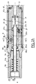
- Figure 1 is a schematic view of a rotary drilling device.
- FIGS. 2A and 2B are views in axial section of means for adjusting the azimuth of the trajectory of a rotary drilling tool according to a first embodiment.
- FIG. 2A is a view in axial section of the upper part of the adjustment means connected to the part of the drill string comprising the first end of this drill string located on the surface.
- FIG. 2B is a view in axial section of the lower part of the adjustment means connected to the drilling tool.
- Figure 3 is an enlarged sectional view of detail 3 of Figure 2A showing a means of junction between the drill string and the tubular body of the azimuth adjustment means.
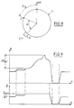
- Figure 4 is an end view along 4 of Figure 2B.
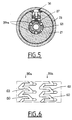
- Figure 5 is a cross-sectional view along 5-5 of Figure 2A.
- Figure 6 is a developed view of the actuation ramps of the device.
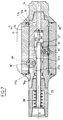
- FIG. 7 is a view in axial section of means for adjusting the azimuth of the trajectory of a drilling tool, according to a second embodiment.
- Figure 7A is a cross-sectional view along A-A of Figure 7 showing a first alternative embodiment of the tubular body of the adjusting means.
- FIG. 7B is a view similar to FIG. 7A showing a second alternative embodiment of the tubular body of the adjustment means shown in FIG. 7.
- Figure 8 is a schematic view showing the principle of azimuth adjustment of the trajectory of a drilling tool.
- FIG. 9 is a representation of the variations as a function of time of the pressure and of the flow rate of the drilling fluid in the drill string, during an operation of operating adjustment means according to the invention.
- FIG. 1 we see a rotary drilling device 1, the drill string 2 of which carries at its end the drilling tool 3 in the process of advancing to produce the borehole 4.
- the end of the drill string located opposite the tool 3 is connected to a rotary drive device 5 of the drill string 2 about its axis.
- the rod 2a located at the upper part of the drill string 2 has a square section and the rotary drive means 5 of the drill string consists of a horizontal rotation table crossed by an opening allowing the engagement of the rod to square section.
- the rotation of the table by a motor assembly makes it possible to drive the square cross-section rod 2a and the drill string 2 in rotation while allowing axial movement of the drill string to carry out the drilling.
- a weight is applied to the upper end of the drill string, in order to exert an axial directional force on the drill string and on the tool allowing its application with sufficient pressure on the bottom of the borehole 4.
- the upper end of the drill string constituting its first end, opposite the second end connected to the drilling tool 3, comprises a drilling fluid injection head 6 connected to the first rod 2a so as to inject the pressurized drilling fluid into its internal bore.
- the drilling fluid flows in the axial direction, inside the drill string and over its entire length so as to reach the lower part of the drilling device, at the level of the tool 3.
- the drilling fluid sweeps the bottom of the borehole 4 then rises to the surface in the annular space located between the drill string and the wall of the borehole 4, by carrying out the driving of the rock debris torn off by the drilling 3.
- the drilling fluid loaded with debris is recovered at the surface, separated from the debris and recycled in a tank 7.
- a pump 8 makes it possible to return the drilling fluid to the injection head 6.
- the drilling device 1 comprises, in its lower part, azimuth adjustment means comprising a tubular body 10 having a support blade 11 projecting radially with respect to the tubular body itself.
- the drill string 2 is rotatably mounted around its axis inside the tubular body 10, the axis of which coincides with the axis of the drill string.
- the rotary drilling device is suspended, at its upper part, by means of a hook 13 from a lifting device making it possible to release the weight exerting a thrust on the drill string 2 and on the tool 3, and lift the drill string and the tool.
- the drilling device comprises a means for rotationally connecting the drill string 2 and the tubular body 10; this device can be operated to be placed in the active position or in the inactive position.
- the tubular body 10 When the connecting device is in its active position, the tubular body 10 is rotated with the drill string. In this case, the drill string 2, the tubular body 10 and the tool 3 are rotated as a whole around the axis of the drill string.
- the drilling device then operates without adjusting the azimuth of the drilling trajectory, the drilling being carried out in the direction of the axis of the drill string.
- the drill string 2 When the device for connecting the drill string 2 and the tubular body 10 is in the inactive position, the drill string 2 can be rotated inside the tubular body 10.
- the application of an axial force FPo on the tool through the drill string produces a lateral reaction force FR2 acting on the wall of the borehole 4.
- the force FR2 is taken up by the support blade 11 of the tubular body 10 (force FR1).
- the support blade 11, under the effect of the force FR1 is kept stationary in rotation against the wall of the borehole 4.
- the direction of the azimuth drilling trajectory is then determined by the angular position of the support blade 11 in the borehole, around the axis of the drill string and by the angle of misalignment of the lower section 15 of the drill string integral with the tool 3 relative to the upper section 16 comprising the first end of the drill string located on the surface.
- FIGS. 2A and 2B a first embodiment of the means according to the invention making it possible to adjust the direction of the drilling trajectory of the device shown in FIG. 1 in azimuth.
- FIGS. 2A and 2B the assembly 20 of the means for adjusting the azimuth of the direction of the trajectory of a drilling device according to the invention has been shown.
- the device 20 is mainly constituted by a first element 21 of the drill string, by a second element 22 of the drill string connected in an articulated manner at the end of the first element and by a tubular body 23 in two parts 23a, 23b defining two successive sections whose axes make an adjustable angle ⁇ , the first element 21 of the drill string being rotatably mounted in the first section of the tubular body and the second element 22 of the drill string being rotatably mounted in the second section of the tubular body 23.
- the first element 21 of the drill string consists of two successive parts 21a and 21b connected together by screwing the tapered tapered end 24 of the first part 21a in a threaded bore of corresponding shape of the second part 21b.
- the first part 21a of the first element 21 has a tapered tapped bore 25 intended to ensure the rigid connection of the first element 21 of the drill string to the upper section comprising the first end of the drill string terminating at the surface and cooperating with the drive means in rotation of the drill string.
- the element 21 is produced in tubular form and comprises in its part 21b a bore 26 with an enlarged diameter in which is mounted all of the control means of the connection device between the drill string and the tubular body 23.
- This assembly comprises a piston 27 mounted movable in translation and in rotation inside the bore 26 and returned towards the first end of the drill string, by a helical spring 28 mounted inside the first part 21a of the element 21 of the drill string.
- the piston 27 is produced in tubular form and delimits a central conduit communicating at its two ends with the bore of the drill string which is traversed, during drilling, by a flow Q of drilling fluid circulating in the axial direction and in the direction given by arrow 29.
- the end of the central duct of the piston 27 located on the downstream side if we consider the circulation of the drilling fluid is profiled so as to constitute a throttled part 27a situated opposite and close to the end part frustoconical in shape of a needle 30 fixed in the axial direction inside of the bore 26, by means of a support device 31 comprising openings for the passage of the drilling fluid at the periphery of the central needle 30.
- the central bore of the element 21 of the drill string has a reduced diameter relative to the bore 26 and opens, through openings 33, into the internal bore of the tubular body 23, around the terminal part of the element 21 of reduced diameter and comprising at its end an opening in the form of a portion of a sphere constituting the female part of a ball joint of articulated assembly of the first element 21 and the second element 22 of the drill string.
- the second element 22 has at its end located in the extension of the element 21 a spherical assembly surface constituting the male part of the ball joint for assembling the elements 21 and 22.
- the ball joint 32 allows the drive in rotation of the second element 22 by the first element 21 while allowing angular misalignment of the second element 22 connected to the drilling tool, relative to the first element 21 connected to the section of the drill string ending at the surface.
- the piston 27 comprises a body 27b in which are machined two sets of ramps 35a and 35b inclined relative to the axis of the first element 21 of the drill string.
- Each of the sets of ramps 35a and 35b comprises several ramps arranged at the periphery of the piston 27, in angular positions regularly spaced around the axis of the piston 27 coinciding with the axis of the element 21.
- the different parts of the sets of ramps 35a and 35b are interconnected by grooves of constant depth machined in the peripheral surface of the piston 27, so that the different parts of the ramps and the grooves of constant depth constitute a continuous track around the peripheral surface of the body 27b of the piston 27, as can be seen in FIGS. 5 and 6.
- each of the tracks comprising the set of ramps 35a or the set of ramps 35b, is applied, by means of springs, one or more locking assemblies 36 allowing the junction between the element 21 of the drill string and the tubular body 23 so as to make the drill string and the tubular body integral in rotation or, on the contrary, to allow rotation of the drill string inside the tubular body, by unlocking the assemblies 36.
- FIG. 3 it can be seen that the assembly 36 is housed in a slot 37 passing through the wall of the tubular element 21 in a radial direction.
- Each of the assemblies 36 comprises a locking finger 38 and an actuating finger 39, the end of the locking finger 38 directed inwards being engaged in a blind bore formed in the axial direction of the actuating finger 39.
- the radial opening 37 of the element 21 comprises a closing plate 40 disposed at its end opening towards the outside, the plate 40 comprising a central opening 40a in which the head 38a of the locking finger 38 is engaged.
- first return spring 42 which tends to push the locking finger 38 outwards.
- a second helical return spring 43 which tends to push the finger 39 inwards, that is to say in the direction of the axis of the piston 27 and element 21.
- a pin or a key 44 is fixed in the bore of the actuating pin 39, projecting radially inwards, so as to engage in an axial slot 38b formed in the lateral surface of the locking finger 38.
- the pin 44 ensures the return of the locking finger 38, under the effect of the spring 43, via the actuating finger 39.
- the head 38a of the locking finger 38 engages, in the active position, as shown in FIG. 3, in an opening 41 of depth h machined in the interior surface of the part 23a of the tubular body 23.
- the locking pin 38 ensures the connection in rotation about their common axis of the element 21 of the drill string and of the tubular body 23.
- the sets of fingers 36 as shown in FIG. 3 are actuated by the piston 27, the ramps 35a and 35b of which are capable of being placed opposite the cooperating end of the actuating finger 39, as it is visible on the figure 3.
- Each of the ramps 35a and 35b has an end part whose depth H1 in the radial direction from the external surface of the piston 27 is minimum and an end part whose depth H2 below the external surface of the piston 27 in the radial direction is maximum.
- the successive junction parts 60 of the set of ramps 35a or 35b are formed by grooves, the bottom of which is either at the depth H1 or at the depth H2.
- the pressure drop is maximum, so that a measurement of the pressure of the drilling fluid carried out on the surface used to control the position of the piston 27 and the achievement of a step of displacement of the control means.
- the flow rate of the drilling fluid is reduced or canceled so that the spring 28 can return the piston to its initial position, the end of the actuating finger 39 being placed in a groove at constant depth to return to a position d balance either at depth H Advisor or at depth H2.
- this finger 39 recalls the locking finger 38 inwards via the pin 44, over a height h , so that the element 21 is unlocked and the drill string is capable of rotating inside the tubular body 23.
- the first part 23a of the tubular body 23 is rotatably mounted on the first element 21 of the drill string, by means of radial bearings 46a, 46b and 47 and an axial bearing 48, so that the first part 23a of the body tubular 23 is coaxial with the first element 21, the axis of which is itself coincident with the axis of the part of the drill string having its first end emerging at the surface.
- seals 49 and 51 are interposed between the element 21 and the tubular body 23, so as to prevent the passage of the drilling fluid between these two parts.
- the second part 23b of the tubular body 23 is mounted on the first part 23a, by means of a frustoconical assembly surface 53 whose axis makes a certain angle (of the order of a few degrees) with the axis of element 21.
- the second part 23b of the tubular body 23 engaged on the first part 23a via the bearing surface 53 can be turned around the axis of this bearing surface and placed in an orientation such that the axis of the bore of the second part 23b of the tubular body 23 makes a certain angle ⁇ with the axis of the bore of the first part 23a of the tubular body 23 coincides with the axis of the element 21.
- the angle ⁇ can be adjusted to a value between 0 and 2 times the angle of misalignment of the frustoconical bearing 53 relative to the axis of the bore of the part 23a of the tubular body.
- Locking screws 54 make it possible to secure and rotate the second part 23b of the tubular body 23 on the first part 23a.
- This adjustment of the angle ⁇ is carried out at the surface, before starting a drilling operation.
- the angle ⁇ is chosen as a function of the desirable amplitude of the azimuth adjustments of the direction of the drilling trajectory.
- the tubular body 23 constitutes a bent tubular element comprising two successive sections whose axes make an angle ⁇ .
- the second part 23b of the tubular body carries three blades 55 projecting radially and in angular positions at 120 ° on its external surface, one of which (55a) is located on the external side of the elbow of the tubular body 23.
- the second element 22 of the drill string comprises a tapered tapered opening 22a allowing the mounting of the drilling tool or of an adaptation piece of this drilling tool at the end of the element 22 opposite its mounted end articulated at the end of element 21.
- the element 22 has an internal bore communicating through openings 56 with the internal bore of the tubular body 23.
- the element 22 is rotatably mounted inside the bore of the second part 23b of the tubular body 23, by means of a radial bearing 57 and an axial bearing 58.
- a seal 59 is interposed between the inner surface of the bore of the tubular body and the outer surface of the second member of the drill string.
- the axis of the second element 22 of the drill string arranged coaxially in the second section of the tubular body 23 therefore forms an angle ⁇ with the axis of the first element 21 of the drill string arranged coaxially with respect to the first section 23a of the bent tubular body 23.
- the drilling device according to the invention has the general structure shown in Figure 1 and means for controlling the azimuth adjustment device as shown in Figures 2A and 2B.
- the tubular body 23 is adjusted so that the angle of misalignment ⁇ of its two sections is adjusted according to the desired azimuth settings.
- the drilling device can operate without azimuth adjustment, the drill string and the tubular body being joined in rotation by junction devices such as the devices 36 shown in FIG. 2A.
- the drill string, the drilling tool and the tubular body 23 rotate together around the axis of the upper part of the drill string combined with the axis of the first element of the drill string engaged in the first section of the tubular body .
- An axial force is transmitted by the drill string, so as to perform drilling along the axis direction of the first part of the drill string.
- elbow tubular body 23 operating as a rigid connection results, during the operation according to the first mode, by a simple widening of the borehole of small amplitude, the angle ⁇ having a small value.
- FIG. 8 which shows very schematically the drill string 2 engaged in a tubular body comprising a support blade 11, a mark Z makes it possible to determine by telemetry the angular position of the train of rods and the blade 11 of the tubular body, around the axis of the drill string and with respect to the direction of magnetic north (NM).
- NM magnetic north
- the azimuth position of the Z coordinate system (defined by the angle Az) can be controlled from the surface, by telemetry, so as to determine the adjustments or corrections to be made to the azimuth direction of the drilling trajectory.
- the angle A between the direction of the mark Z and the radial direction Y of the blade 11 is fixed at a determined value, in the first operating mode, the engagement of the locking fingers in determined openings of the tubular body defining an indexing angular of the tubular body with respect to the drill string.
- the azimuth adjustment of the drilling path (second mode of operation of the device) is obtained, as indicated above, by adjusting the angular position of the support blade 11 in the borehole and by unlocking the drill string drilling, so as to allow it to rotate inside the tubular body, after pressing the blade 11 against the wall of the borehole, in a position determined, under the effect of the lateral forces involved and resulting from the axial force on the drill string.
- transition from the first operating mode without azimuth adjustment to the second operating mode with azimuth adjustment is therefore achieved by releasing the locking means of the tubular body on the drill string and by orienting the tubular body so that the blade support is in the desired position, as will be described below.
- the drilling device being in operation according to the first mode without azimuth adjustment, to pass to the second mode of operation with azimuth adjustment, we initially release the axial force on the tool exerted by the through the drill string, without removing the tool from the bottom of the borehole and the rotation of the drill string ensuring drilling is stopped.
- the angular position of the blade 11 (or 55a) is adjusted relative to the magnetic north, so as to carry out the azimuth adjustment in the desired direction, by turning the drill string from the surface by a determined angle.
- This rotation of the drill string causes the same rotation of the tubular body integral with the first element of the drill string and the angular position of the support blade.
- the axial force is again applied to the drill string so as to generate a reaction force FR1 (see FIG. 1) at the level of the support blade, which fixes the angular position of the support blade and the tubular body 10.
- the flow rate is increased by so as to pass it to the activation value of the control means.
- Pressure recording tracks the movement of the piston and the position of the actuating fingers from the surface.
- the circulation of the drilling fluid in the drill string is interrupted, so that the piston 27 is recalled by the spring 28, in the opposite direction of the circulation of the drilling fluid.
- the ends of the actuating fingers move in contact with a groove 60 at constant depth H2 joining two successive ramps.
- the actuating fingers pass from the ramp to the groove at constant depth by a rotation of the piston 27 about its axis, when the actuating fingers come into contact at the end of the ramps with curved joining parts between the ramps 35 and the grooves 60 at constant depth.
- the piston is then in its equilibrium position and the fingers 38 are unlocked.
- the flow rate of the drilling fluid is restored to the value QF, which does not cause any displacement of the piston 27, the flow rate QF being less than the actuation flow rate QACT.
- the pressure of the drilling fluid after passing from its maximum value to the zero value rises to an intermediate value corresponding to the substantially constant value of the pressure during drilling.
- the drill string is put back in rotation in order to restart drilling.
- the drill string is free to rotate in the tubular body 23, so that the first element 21 of the drill string drives the second element 22 in rotation, this second element secured to the drilling tool having an axis making an angle ⁇ with the first element disposed in the first section of the tubular body 23.
- the drill string arranged inside the bent tubular body has a misalignment identical to the misalignment of the two sections of the tubular body; during drilling, the advancement of the drilling tool causes advancement of the drill string and of the tubular body integral in translation with this drill string, the support blade 55a being driven in rubbing contact with the wall of the drilling hole drilling.
- the axial force exerted via the drill string on the drilling tool and the tool is peeled from the bottom of the hole.
- the flow rate of the drilling fluid is increased to the activation value QACT, so as to pass the end of the actuating fingers in contact with the ramps with variable depth, from level H2 to level H1 where the fingers of locking 38 are pushed outwards by the return springs 42 and 43.
- the flow rate of the drilling fluid is canceled, so as to return the piston to its equilibrium position.
- the drill string is rotated inside the tubular body in order to engage the locking fingers 38, the heads 38a of the fingers 38 pushed back by the springs 43 coming to engage in the corresponding openings 41 when the heads and the openings came in coincidence.
- FIGS. 7, 7A and 7B there is shown a second embodiment of the means for adjusting the azimuth of the trajectory of a drilling tool operating according to the general principle set out above with reference to FIG. 1 and using remote control means similar to the means described with reference to FIGS. 2A and 2B.
- the implementation of these means for passing from an operating mode without azimuth adjustment to an operating mode with azimuth adjustment or vice versa is substantially analogous to the process which has just been described relating to the realization of FIGS. 2A and 2B.
- FIGS. 2A and 2B on the one hand and 7 on the other hand bear the same references with, however, the exponent ' (prime) for the elements represented in FIG. 7.
- These elements constitute the junction device between the drill string and the tubular body and its control means which are produced in a similar manner in the case of the first embodiment and in the case of the second embodiment.
- the tubular body 70 rotatably mounted on the drill string and integral in translation with this drill string is produced in the form of a stabilizer with a support blade of the type used to make trajectory corrections on drill string, by deformation of the drill string under the effect of lateral forces exerted by the stabilizer on the edge of the borehole.
- the tubular body 70 is rotatably mounted on the drill string and the drill string can be integral in rotation with the tubular body 70 or, on the contrary, made free to rotate in the tubular body 70, by means of remote control means using drilling fluid of the type of those which have been described above.
- the tubular body 70 is rotatably mounted on an intermediate part 72 of the drill string connected at one of its ends to a first screw connection 73 allowing the part 72 to be fixed to the part of the drill string having its first end emerging at the surface and, at its other end, to a second screw connection 74 making it possible to connect the intermediate piece 72 to the part of the drill string carrying the drilling tool.
- the tubular body 70 is rotatably mounted on the intermediate piece 72 by means of roller bearings 76a and 76b and held integral in translation with the drill string between a shoulder of the piece 72 and a shoulder of the second fitting 74.
- Ball bearings and seals 77a and 77b are interposed between the body 70 and the shoulders of the drill string.
- the tubular body 70 comprises a support blade 71 and two guide blades 78a and 78b projecting radially outwards.
- the outer edges of the guide blades 78a and 78b lie on a circular contour 79 returned on the axis of the drill string whose diameter corresponds to the diameter D of the borehole.
- the outer edge of the support blade 71 is projecting relative to the contour 79 of a radial length e .
- FIG. 7B an alternative embodiment 70 ′ of the tubular body 70 is shown, which comprises two guide blades 78 ′ a and 78 ′ b and a support blade 71 ′ whose external edges lie on a circle 79 ′ whose radius has a length D / 2 - h slightly less than the radius of the borehole.
- the circle 79 ' is centered at a point located at a distance k from the axis of the drill string and the intermediate piece 72.
- the support blade 71' is in its position d '' maximum offset.
- the azimuth adjustment means shown in FIGS. 7, 7A and 7B can be controlled in a similar manner to the adjustment means shown in FIGS. 2A, 2B and 3 to 6, by means of maneuverable joining devices 36 'comprising locking fingers 38 'actuated by the ramps 35'a and 35'b of a piston 27' and by return springs.
- the piston 27 ' is moved in one direction by the force created by the pressure drop at the opening 27'a cooperating with the frustoconical needle 30' and in the other direction by the return spring 28 '.
- the blade 71 (or 71 ′) is pressed against the edge of the borehole in a determined angular position, as described above.
- the fingers 38 ' are then unlocked by remote control, so as to allow rotation of the drill string inside the tubular part 70 or 70 '.
- the azimuth adjustment is carried out by angular misalignment of the lower part of the drill string carrying the tool such as the part 15 shown in FIG. 1, relative to the upper part 16 comprising the first end of the drill string, under the effect of the radial forces brought into play during drilling and acting on part 15 of the drill string.
- the azimuth adjustment therefore depends on the angular position of the support blade and its eccentricity and on the geometric and mechanical characteristics of the part 15 of the drill string.
- the device according to the invention therefore makes it possible to carry out an azimuth adjustment controlled remotely from the trajectory of a drilling tool, in the case of rotary drilling.
- the drilling device operates with azimuth adjustment of the trajectory of the drilling tool, it is possible to return by remote control to an operating mode without azimuth adjustment of the trajectory.
- the transition from one operating mode to the other is carried out quickly and safely, the control of the control means being able to be carried out from the surface, for example by measuring the pressure of the drilling fluid.
- the invention therefore makes it possible to adjust the trajectory of a drilling tool in azimuth, without using a downhole motor.
- control means for locking or unlocking the tubular body on the drill string can be achieved. in a form different from that which has been described.
- These control means using the pressure or the flow rate of the drilling fluid are well known in the technique of directional drilling at great depth.
- the joining means between the drill pipe and the tubular body can be produced in a form different from that which has been described using fingers placed in radial directions.
- the tubular body can be produced in a form different from those which have been described, this tubular body being able to be produced in one or more pieces, with or without the possibility of adjusting the misalignment angle or the eccentricity of the blade. support.
Landscapes
- Life Sciences & Earth Sciences (AREA)
- Engineering & Computer Science (AREA)
- Geology (AREA)
- Mining & Mineral Resources (AREA)
- Physics & Mathematics (AREA)
- Environmental & Geological Engineering (AREA)
- Fluid Mechanics (AREA)
- General Life Sciences & Earth Sciences (AREA)
- Geochemistry & Mineralogy (AREA)
- Earth Drilling (AREA)
Claims (11)
- Rotary-Bohrvorrichtung, die Azimutsteuerungsmittel zur Fernsteuerung des Weges des Bohrwerkzeugs umfasst und aus einem Bohrgestänge (2) besteht mit einem ersten Endteil, das mit Mitteln (5), die das Bohrgestänge um seine Achse in Drehung setzen und eine Kraft in achsialer Richtung auf das Bohrgestänge anwenden, und mit Mitteln (6) zur Zufuhr der Bohrflüssigkeit des Bohrgestänges verbunden ist, wodurch eine achsiale Zirkulation der Flüssigkeit bis zum Bohrwerkzeug (3), das mit einem zweiten Endteil des Bohrgestänges verbunden ist, sichergestellt wird, wobei die Azimutsteuerungsmittel des Weges des Bohrwerkzeugs (3) bestehen aus:- einem röhrenförmigen Körper (10, 23, 70, 70') mit mindestens einer radial nach aussen hervorstehenden Stützzunge (11, 55a, 71, 71'), der auf dem Bohrgestänge (2) rotierend um seine Achse, die mit der Achse des Bohrgestänges (2) verschmolzen ist, montiert und solidarisch mit der Verschiebung des Bohrgestänges ist,- und einem Verbindungsmittel (36, 36') zwischen dem Bohrgestänge (2) und dem röhrenförmigen Körper (10, 23, 70), das vom Bohrgestänge (2) getragen wird, das beweglich ist zwischen einer aktiven und einer inaktiven Stellung und fernsteuerbar dank der Steuerungsmittel (27, 30, 27', 30'), die durch die im Bohrgestänge (2) zirkulierende Flüssigkeit in Tätigkeit gesetzt werden, wobei das Verbindungsmittel in seiner aktiven Stellung die Mitnahme in Drehung des röhrenförmigen Körpers (10, 23, 70) durch das Bohrgestänge (2) und in seiner inaktiven Stellung die Drehung des Bohrgestänges (2) im Innern des röhrenförmigen Körpers ermöglicht, wobei die Azimutsteuerung des Weges des Bohrwerkzeugs (3) nun durch das Aufstützen der Zunge (11, 55a, 71, 71') des röhrenförmigen Körpers auf die Wand des Bohrloches (4) in einer festgelegten Position sichergestellt wird, dadurch gekennzeichnet, daß das Bohrgestänge (2) zwei Elemente (21, 22) eines hinter dem anderen angeordnet umfasst, die untereinander gelenkig mit einem ihrer Endteile verbunden und solidarisch mit ihren anderen Endteilen sind, bei dem einem oder dem ersten Element (21) mit einem Teil des Bohrgestänges, das das erste Endteil umfasst, und bei dem anderen oder zweiten Element (22) mit dem Bohrwerkzeug (3), und daß der röhrenförmige Körper (23) zwei aufeinanderfolgende Abschnitte (23a, 23b) umfasst, deren Achsen einen Winkel α untereinander bilden, wobei das erste Element (21) des Bohrgestänges rotierend um seine Achse in einem ersten Abschnitt (23a) des röhrenförmigen Körpers (23) montiert ist und das zweite Element (22) rotierend um seine Achse in einem zweiten Abschnitt (23b) des gebogenen röhrenförmigen Körpers (23) montiert ist, wobei die Azimutregulierung des Weges des Bohrwergzeugs (3) durch das Anhalten der Drehung des gebogenen röhrenförmigen Körpers (23), dessen Zunge (55A) auf die Wand des Bohrloches in einer festgelegten Position aufgestützt wird, und durch das Abweichen aus der Winkelausrichtung der beiden Elemente (21, 22) des Bohrgestänges im Innern des gebogenen röhrenförmigen Körpers (23) sichergestellt wird.
- Bohrvorrichtung nach Anspruch 1, dadurch gekennzeichnet, daß der röhrenförmige Körper zwei Teile (23a,23b) in Röhrenform umfasst, wobei einer dieser Teile (23a) eine Auflagefläche (53) hat, deren Symetriedrehachse im Winkel zur Achse des Teiles (23a) angeordnet ist, das Element (23b) eine entsprechende Auflagefläche aufweist und um die Achse der Auflagefläche gedreht werden kann, um so den Winkel der Abweichausrichtung α zwischen den röhrenförmigen Teilen (23a, 23b), die die zwei aufeinanderfolgenden Abschnitte des röhrenförmigen Körpers (23) bilden, in einem festgelegten Wert zu regulieren.
- Rotary-Bohrvorrichtung, die Azimutsteuerungsmittel zur Fernsteuerung des Weges des Bohrwerkzeugs umfasst und aus einem Bohrgestänge (2) besteht mit einem ersten Endteil, das mit Mitteln (5), die das Bohrgestänge ume seine Achse in Drehung setzen und eine Kraft in achsialer Richtung auf das Bohrgestänge anwenden, und mit Mitteln (6) zur Zufuhr der Bohrflüssigkeit des Bohrgestänges verbunden ist, wodurch eine achsiale Zirkulation der Flüssigkeit bis zum Bohrwerkzeug (3), das mit einem zweiten Endteil des Bohrgestänges verbunden ist, sichergestellt wird, wobei die Azimutsteuerungsmittel des Weges des Bohrwerkzeugs (3) bestehen aus:- einem röhrenförmigen Körper (10,23, 70, 70') mit mindestens einer radial nach aussen hervorstehenden Stützzunge (11, 55a, 71, 71'), der auf dem Bohrgestänge (2) rotierend um seine Achse, die mit der Achse des Bohrgestänges (2) verschmolzen ist, montiert und solidarisch mit der Verschiebung des Bohrgestänges ist,- und einem Verbindungsmittel (36, 36') zwischen dem Bohrgestänge (2) und dem röhrenförmigen Körper (10,23, 70), das vom Bohrgestänge (2) getragen wird, das beweglich ist zwischen einer aktiven und einer inaktiven Stellung und fernsteuerbar dank der Steuerungsmittel (27, 30, 27', 30'), die durch die im Bohrgestänge (2) zirkulierende Flüssigkeit in Tätigkeit gesetzt werden, wobei das Verbindungsmittel in seiner aktiven Stellung die Mitnahme in Drehung des röhrenförmigen Körpers (10, 23, 70) durch das Bohrgestänge (2) und in seiner inaktiven Stellung die Drehung des Bohrgestänges (2) im Innern des röhrenförmigen Körpers ermöglicht, wobei die Azimutsteuerung des Weges des Bohrwerkzeugs (3) nun durch das Aufstützen der Zunge (11, 55a, 71, 71') des röhrenförmigen Körpers auf die Wand des Borloches (4) in einer festgelegten Position sichergestellt wird, dadurch gekennzeichnet, daß der röhrenförmige Körper (70, 70') ausgeführt ist in Form eines Stabilisators, wobei er eine Stützzunge (71, 71') hat, die nach aussen in einer radialen Richtung in Bezug auf eine kreisförmige Aussenlinie (79, 79') hervorsteht, er auf der Achse des Bohrgestänges zentriert ist, er einen Durchmesser gleich dem des Durchmessers eines mit dem Bohrwerkzeug hergestellten Bohrloches hat, um eine Winkelabweichausrichtung der zwei aufeinanderfolgenden Abschnitte (15, 16) des Bohrgestänges durch Biegung des Bohrgestänges unter der Einwirkung von lateralen Kräften, die sich zwischen der Stützzunge (71, 71') und dem Bohrloch auswirken, wobei die Zunge (71, 71') auf der Wand des Bohrlochs aufliegt, in einer festgelegten Position hervorzurufen.
- Bohrvorrichtung nach irgendeinem der Ansprüche 1 bis 3, dadurch gekennzeichnet, daß das Verbindungsmittel (36, 36') zwischen dem Bohrgestänge (2) und dem gebogenen röhrenförmigen Körper (23, 70, 70') mindestens aus einem Fixierfinger (38,38') besteht, der in radialer Richtung angeordnet ist, der nach aussen durch eine Feder (42), zurückgestellt wird, um so in eine Öffnung (41), die in der inneren Oberfläche des röhrenförmigen Körpers (23, 70, 70') ausgespart ist, einzugreifen.
- Bohrvorrichtung nach Anspruch 4, dadurch gekennzeichnet, daß die Steuerungsmittel des Verbindungsmittels (36, 36') aus einem Antriebsfinger (39) des Fixierfingers (38, 38') bestehen, wobei der Antrieb des Fixierfingers (38, 38') mittels der Feder (42), die zwischen den Antriebsfinger (39) und den Fixierfinger (38, 38') geschaltet ist, und eines Metallstücks (44) sichergestellt wird, das in eine Öffnung (38b) des Fixierfingers (38) eingreift, wobei eine Feder (43) die Rückstellung nach innen in der radialen Richtung des Antriebsfingers (39) sicherstellt, so daß ein Endteil des Antriebsfingers (39) mit einer Antriebsfläche (35a, 35b) eines Steuerungsmittels (27, 27') des Antriebsfingers (39) in Kontakt kommt zu seiner Verschiebung in radialer Richtung durch achsiale Verschiebung der Steuerungsmittel (27, 27'), die durch die im Borgestänge zirkulierende Flüssigkeit oder durch ein Rückstellmittel (28, 28') angetrieben werden.
- Bohrvorrichtung nach Anspruch 5, dadurch gekennzeichnet, daß das Steuerungsmittel (27, 27') aus einem röhrenförmigen Kolben besteht, der gleitend und rotierend in der Bohrung des Bohrgestänges montiert ist und an einem seiner Endteile ein profiliertes Teil (27a, 27'a) aufweist, das dazu bestimmt ist, mit einem profilierten Teil von entsprechender Form (30, 30') zusammenzuwirken, um den Verlust an Belastung auf der Zirkulation der Bohrflüssigkeit auf beiden Seiten des Kolbens (27, 27') bei den Verschiebungen des Kolbens in der Zirkulationsrichtung der Bohrflüssigkeit zu erhöhen, wobei der Kolben auf seiner äusseren Oberfläche Antriebsrampen (35a, 35b, 35'a, 35'b) aufweist, die in Bezug auf die dem Kolben (27, 27') und dem Bohrgestänge gemeinsame Achse geneigt und untereinander verbunden sind durch Rillen mit konstanter Tiefe, deren Boden parallel zur Achse des Kolbens (27, 27') ist, um eine kontinuierliche Spur um den Kolben (27, 27') zu bilden, auf der das Ende des Antriebsfingers (39) abgestützt wird durch die Feder (43), die zwischen die Stützflächen des Bohrgestänges und den Antriebsfinger (39) geschaltet ist.
- Bohrvorrichtung nach irgendeinem der Ansprüche 1 und 2, dadurch gekennzeichnet, daß das erste Element (21) und das zweite Element (22) des Bohrgestänges in ihrem Endteil, der die gelenkige Verbindung sicherstellt, Öffnungen (33, 56) aufweisen, die ihre Mittelbohrung mit dem Innenvolumen des röhrenförmigen Körpers (23) in Verbindung bringen, so daß eine Zirkulation der Bohrflüssigkeit an der Peripherie der Endteile hergestellt wird, wobei die gelenkige Verbindung der Element (21, 22) des Bohrgestänges sichergestellt wird, um eine kontinuierliche Zirkulation der Bohrflüssigkeit bis zum Bohrwerkzeug (3) zu erreichen.
- Rotary-Bohrverfahren mit Azimutregulierung des Weges des Bohrwerkzeugs unter Verwendung einer Vorrichtung nach irgendeinem der Ansprüche 1 bis 7, dadurch gekennzeichnet, daß man zwischen zwei Bohrphasen das Verbindungsmittel (36, 36') zwischen dem Bohrgestänge und dem röhrenförmigen Körper (10, 23, 70, 70') mittels der Bohrflüssigkeit betätigt, entweder in der Richtung, in der das Verbindungsmittel (36, 36') von seiner aktiven Stellung in seine inaktive Stellung gebracht wird, wobei die Bohrvorrichtung dann von einer Arbeitsweise ohne Azimutregulierung der Richtung des Bohrweges in eine Arbeitsweise mit Azimutregulierung übergeht, oder in der Richtung, in der das Verbindungsmittel (36, 36') von seiner inaktiven Stellung in seine aktive Stellung gebracht wird, wobei die Bohrvorrichtung dann von einer Arbeitsweise mit Amzimutregulierung des Bohrweges in eine Arbeitsweise ohne Azimutregulierung des Bohrweges übergeht.
- Verfahren nach Anspruch 8, dadurch gekennzeichnet, daß man für den Übergang einer Arbeitsweise der Bohrvorrichtung ohne Azimutregulierung des Bohrweges zu einer Arbeitsweise mit Azimutregulierung die Achsialkraft auf das Bohrwerkzeug (3) außer Kraft setzt und die Drehung des Bohrgestänges anhält,- man die Winkelstellung der Stützzunge (11, 55a, 71, 71') des röhrenförmigen Körpers (10, 23, 70, 70') reguliert, indem man das Bohrgestänge ab dem ersten Endteil dreht,- man die Achsialkraft wieder auf das Bohrgestänge anwendet,- man das Verbindungsmittel (36, 36') betätigt, um es von seiner aktiven Stellung in seine inaktive Stellung mittels der Bohrflüssigkeit zu bringen,- man das Bohrgestänge wieder in Drehung setzt, um die Bohrung wiederaufzunehmen, wobei der Körper (10, 23, 70, 70') gestützt durch seine Zunge (11, 55a, 71, 71') auf das Bohrloch, unbeweglich in der Drehung bleibt und das Bohrgestänge, das sich im Inneren des Röhrenkörpers (10, 23, 70, 70') dreht, die Azimutregulierung des Bohrweges ausführt.
- Bohrverfahren nach Anspruch 8, dadurch gekennzeichnet, daß zur Verwirklichung des Übergangs von der Arbeitsweise mit Azimutregulierung des Bohrweges zur Arbeitsweise ohne Azimutregulierung des Bohrweges- man die Achsialkraft auf das Bohrgestänge außer Kraft setzt,- man das Verbindungsmittel (36, 36') zwischen dem Bohrgestänge und dem röhrenförmigen Körper (10, 23, 70, 70') in der Art steuert, daß man es von seiner inaktiven Stellung in seine aktive Stellung bringt durch Betätigung mittels der zirkulierenden Bohrflüssigkeit und durch Drehung, die durch sein erstes Endteil gesteuert wird, des Bohrgestänges um seine Achse im Innern der röhrenförmigen Körpers (10, 23, 70, 70'),- man das Bohrgestänge wieder in kontinuierliche Drehung setzt, wobei das ganze bestehend aus Bohrgestänge (2) und aus dem röhrenförmigen Körper (10, 23, 70, 70') solidarisch in Drehung ist.
- Verfahren nach irgendeinem der Ansprüche 8 bis 10, dadurch gekennzeichnet, daß die Steuerung des Verbindungsmittels (36, 36') für seine Verlagerung zwischen seiner aktiven und seiner inaktiven Stellung sichergestellt wird durch die Erhöhung des Durchsatzes der Bohrflüssigkeit über einen Aktivierungswert QACT, worauf der Durchsatz der Bohrflüssigkeit dann annuliert wird, das Verbindungsmittel dann (36, 36') in seiner neuen Stellung ist.
Applications Claiming Priority (2)
| Application Number | Priority Date | Filing Date | Title |
|---|---|---|---|
| FR9002876A FR2659383B1 (fr) | 1990-03-07 | 1990-03-07 | Dispositif de forage rotary comportant des moyens de reglage en azimut de la trajectoire de l'outil de forage et procede de forage correspondant. |
| FR9002876 | 1990-03-07 |
Publications (2)
| Publication Number | Publication Date |
|---|---|
| EP0456526A1 EP0456526A1 (de) | 1991-11-13 |
| EP0456526B1 true EP0456526B1 (de) | 1994-05-18 |
Family
ID=9394470
Family Applications (1)
| Application Number | Title | Priority Date | Filing Date |
|---|---|---|---|
| EP91400524A Expired - Lifetime EP0456526B1 (de) | 1990-03-07 | 1991-02-26 | Vorrichtung und Verfahren zum Steuern des Azimuts der Fahrt eines Drehbohrwerkzeuges |
Country Status (5)
| Country | Link |
|---|---|
| US (1) | US5131479A (de) |
| EP (1) | EP0456526B1 (de) |
| CA (1) | CA2037409C (de) |
| FR (1) | FR2659383B1 (de) |
| NO (1) | NO303350B1 (de) |
Families Citing this family (32)
| Publication number | Priority date | Publication date | Assignee | Title |
|---|---|---|---|---|
| CA2059910C (en) * | 1992-01-23 | 2001-10-30 | Paul Lee | Adjustable drilling mechanism |
| US5253721A (en) * | 1992-05-08 | 1993-10-19 | Straightline Manufacturing, Inc. | Directional boring head |
| GB9210846D0 (en) * | 1992-05-21 | 1992-07-08 | Baroid Technology Inc | Drill bit steering |
| US5547031A (en) * | 1995-02-24 | 1996-08-20 | Amoco Corporation | Orientation control mechanism |
| US6736226B2 (en) * | 1998-02-03 | 2004-05-18 | Cutting Edge Technologies, Llc | Method and apparatus for boring through a solid material |
| US6092610A (en) * | 1998-02-05 | 2000-07-25 | Schlumberger Technology Corporation | Actively controlled rotary steerable system and method for drilling wells |
| US6158529A (en) * | 1998-12-11 | 2000-12-12 | Schlumberger Technology Corporation | Rotary steerable well drilling system utilizing sliding sleeve |
| US6109372A (en) * | 1999-03-15 | 2000-08-29 | Schlumberger Technology Corporation | Rotary steerable well drilling system utilizing hydraulic servo-loop |
| US7136795B2 (en) | 1999-11-10 | 2006-11-14 | Schlumberger Technology Corporation | Control method for use with a steerable drilling system |
| DE60011587T2 (de) | 1999-11-10 | 2005-06-30 | Schlumberger Holdings Ltd., Road Town | Steuerungsverfahren für steuerbares bohrsystem |
| US7251590B2 (en) * | 2000-03-13 | 2007-07-31 | Smith International, Inc. | Dynamic vibrational control |
| US9482055B2 (en) * | 2000-10-11 | 2016-11-01 | Smith International, Inc. | Methods for modeling, designing, and optimizing the performance of drilling tool assemblies |
| US7693695B2 (en) | 2000-03-13 | 2010-04-06 | Smith International, Inc. | Methods for modeling, displaying, designing, and optimizing fixed cutter bits |
| US8589124B2 (en) * | 2000-08-09 | 2013-11-19 | Smith International, Inc. | Methods for modeling wear of fixed cutter bits and for designing and optimizing fixed cutter bits |
| FR2813340B1 (fr) * | 2000-08-29 | 2002-12-06 | Geoservices | Dispositif pour deplacer radialement deux organes l'un par rapport a l'autre et dispositif de forage en comportant application |
| GB0101633D0 (en) * | 2001-01-23 | 2001-03-07 | Andergauge Ltd | Drilling apparatus |
| US6550548B2 (en) | 2001-02-16 | 2003-04-22 | Kyle Lamar Taylor | Rotary steering tool system for directional drilling |
| US20030127252A1 (en) | 2001-12-19 | 2003-07-10 | Geoff Downton | Motor Driven Hybrid Rotary Steerable System |
| WO2003096075A1 (en) | 2002-05-13 | 2003-11-20 | Camco International (Uk) Limited | Recalibration of downhole sensors |
| WO2004065835A2 (en) * | 2003-01-14 | 2004-08-05 | Tt Technologies, Inc. | Connection assembly for directional drilling |
| US20040195008A1 (en) * | 2003-03-03 | 2004-10-07 | Broom Gilbert R. | Method and apparatus for tapping a blast furnace |
| US20050098355A1 (en) * | 2003-03-03 | 2005-05-12 | Broom Gilbert R. | Method and apparatus for boring through a solid material |
| CA2531397C (en) * | 2003-07-09 | 2010-04-13 | Smith International, Inc. | Methods for modeling wear of fixed cutter bits and for designing and optimizing fixed cutter bits |
| US7441612B2 (en) * | 2005-01-24 | 2008-10-28 | Smith International, Inc. | PDC drill bit using optimized side rake angle |
| WO2010080476A2 (en) * | 2008-12-18 | 2010-07-15 | Smith International, Inc. | Method of designing a bottom hole assembly and a bottom hole assembly |
| US9500031B2 (en) | 2012-11-12 | 2016-11-22 | Aps Technology, Inc. | Rotary steerable drilling apparatus |
| WO2015117151A2 (en) | 2014-02-03 | 2015-08-06 | Aps Technology, Inc. | System, apparatus and method for guiding a drill bit based on forces applied to a drill bit |
| US10113363B2 (en) | 2014-11-07 | 2018-10-30 | Aps Technology, Inc. | System and related methods for control of a directional drilling operation |
| US10233700B2 (en) | 2015-03-31 | 2019-03-19 | Aps Technology, Inc. | Downhole drilling motor with an adjustment assembly |
| US10890030B2 (en) | 2016-12-28 | 2021-01-12 | Xr Lateral Llc | Method, apparatus by method, and apparatus of guidance positioning members for directional drilling |
| US11255136B2 (en) * | 2016-12-28 | 2022-02-22 | Xr Lateral Llc | Bottom hole assemblies for directional drilling |
| CN107313739B (zh) * | 2017-09-06 | 2020-07-17 | 成都百胜野牛科技有限公司 | 流体分隔装置、井道结构及石油或天然气的生产方法 |
Family Cites Families (12)
| Publication number | Priority date | Publication date | Assignee | Title |
|---|---|---|---|---|
| US2819040A (en) * | 1956-07-13 | 1958-01-07 | Eastman Oil Well Survey Co | Deflecting tool |
| US3156310A (en) * | 1959-12-07 | 1964-11-10 | Eastman Oil Well Survey Co | Stabilized knuckle joint |
| FR1486421A (fr) * | 1966-05-16 | 1967-06-30 | Drilco Oil Tools | Appareil pour le forage du sol |
| US3637032A (en) * | 1970-01-22 | 1972-01-25 | John D Jeter | Directional drilling apparatus |
| US4076084A (en) * | 1973-07-16 | 1978-02-28 | Amoco Production Company | Oriented drilling tool |
| GB2091780B (en) * | 1981-01-23 | 1984-08-01 | Coal Industry Patents Ltd | Drilling methods and equipment |
| US4597454A (en) * | 1984-06-12 | 1986-07-01 | Schoeffler William N | Controllable downhole directional drilling tool and method |
| US4813274A (en) * | 1987-05-27 | 1989-03-21 | Teleco Oilfield Services Inc. | Method for measurement of azimuth of a borehole while drilling |
| US4804051A (en) * | 1987-09-25 | 1989-02-14 | Nl Industries, Inc. | Method of predicting and controlling the drilling trajectory in directional wells |
| FR2622920A1 (fr) * | 1987-11-09 | 1989-05-12 | Smf Int | Dispositif de reglage de la direction d'avancement d'un outil de forage et procede de reglage correspondan |
| US4895214A (en) * | 1988-11-18 | 1990-01-23 | Schoeffler William N | Directional drilling tool |
| FR2641387B1 (fr) * | 1988-12-30 | 1991-05-31 | Inst Francais Du Petrole | Methode et dispositif de telecommande d'equipement de train de tiges par sequence d'information |
-
1990
- 1990-03-07 FR FR9002876A patent/FR2659383B1/fr not_active Expired - Lifetime
-
1991
- 1991-02-26 EP EP91400524A patent/EP0456526B1/de not_active Expired - Lifetime
- 1991-02-28 US US07/662,251 patent/US5131479A/en not_active Expired - Fee Related
- 1991-03-01 CA CA002037409A patent/CA2037409C/fr not_active Expired - Fee Related
- 1991-03-05 NO NO910856A patent/NO303350B1/no not_active IP Right Cessation
Also Published As
| Publication number | Publication date |
|---|---|
| US5131479A (en) | 1992-07-21 |
| CA2037409A1 (fr) | 1991-09-08 |
| NO910856D0 (no) | 1991-03-05 |
| CA2037409C (fr) | 2001-07-03 |
| FR2659383B1 (fr) | 1992-07-10 |
| FR2659383A1 (fr) | 1991-09-13 |
| EP0456526A1 (de) | 1991-11-13 |
| NO303350B1 (no) | 1998-06-29 |
| NO910856L (no) | 1991-09-09 |
Similar Documents
| Publication | Publication Date | Title |
|---|---|---|
| EP0456526B1 (de) | Vorrichtung und Verfahren zum Steuern des Azimuts der Fahrt eines Drehbohrwerkzeuges | |
| EP0190529B1 (de) | Durchflussferngesteuerte Vorrichtung zum Betätigen insbesondere von Stabilisatoren in einem Bohrstrang | |
| CA1128925A (fr) | Raccord coude a angle variable pour forages diriges | |
| CA2276851C (fr) | Dispositif et methode de controle de la trajectoire d'un forage | |
| EP0574326B1 (de) | Einrichtung, System und Verfahren zum Bohren und Ausrüsten eines seitlichen Bohrloches | |
| EP0388315B1 (de) | Verfahren und Vorrichtung zum Aufzeichnen von Bohrlochmessungen mit einem Sensor, der die Bohrlochwand entlang des Umfangs abtastet, insbesondere um diesen Sensor zu kalibrieren | |
| EP0212316B1 (de) | Bohrstrang zum Ablenken der Bohrrichtung, Verfahren zum Bedienen dieses Stranges und in diesem Strang benutzte Ablenkvorrichtung | |
| FR2790510A1 (fr) | Procede et dispositif de controle de debit en fond de puits, a commande decouplee | |
| CA2006920C (fr) | Equipement pour garniture de forage comportant un element a actionner, un moteur et des moyens de commande | |
| CA1230869A (fr) | Atterrisseur pour aeronef | |
| EP0344028A1 (de) | Vorrichtung und Verfahren zum Schrauben und Losschrauben einer Mutter auf einem Verbindungselement | |
| EP0286500A1 (de) | Bohrvorrichtung entlang einer kontrollierbaren Bewegungsbahn und dazugehörendes Steuerungsverfahren | |
| EP0388296B1 (de) | Interventionsvorrichtung, insbesondere zur Prüfung, Inspektion und Wartung von Wärmeaustauschern | |
| CA1177055A (fr) | Raccord coude a angle variable pour forages diriges | |
| FR2643610A1 (fr) | Atterrisseur d'avion a roues orientables lors du relevage de l'atterrisseur | |
| EP1746213A1 (de) | Vorrichtung zur Herstellung einer Schlitzwand aus einer Mischung von Boden und Bindemittel | |
| FR2579662A1 (fr) | Dispositif de forage a trajectoire controlee | |
| EP0546135B1 (de) | Vorrichtung zum Steuern des Azimuts der Fahrt eines Drehbohrwerkzeuges | |
| EP2382370B1 (de) | Verfahren zur trennung einer vorrichtung zur übertragung von fluid zwischen dem grund eines gewässers und der oberfläche sowie zugehörige transfervorrichtung | |
| EP3056435B1 (de) | Halte- und lösevorrichtung eines ferngesteuerten geräts | |
| FR2622920A1 (fr) | Dispositif de reglage de la direction d'avancement d'un outil de forage et procede de reglage correspondan | |
| FR2692316A1 (fr) | Système et méthode de forage et d'équipement de forage latéral, application à l'exploitation de gisement pétrolier. | |
| FR2607107A1 (fr) | Rotor d'helicoptere | |
| EP2206876B1 (de) | Bohrkopf für Tunnelbohrmaschine | |
| FR2519686A2 (fr) | Raccord coude a angle variable pour forages diriges |
Legal Events
| Date | Code | Title | Description |
|---|---|---|---|
| PUAI | Public reference made under article 153(3) epc to a published international application that has entered the european phase |
Free format text: ORIGINAL CODE: 0009012 |
|
| AK | Designated contracting states |
Kind code of ref document: A1 Designated state(s): GB IT NL |
|
| 17P | Request for examination filed |
Effective date: 19911011 |
|
| 17Q | First examination report despatched |
Effective date: 19921208 |
|
| GRAA | (expected) grant |
Free format text: ORIGINAL CODE: 0009210 |
|
| AK | Designated contracting states |
Kind code of ref document: B1 Designated state(s): GB IT NL |
|
| ITF | It: translation for a ep patent filed | ||
| GBT | Gb: translation of ep patent filed (gb section 77(6)(a)/1977) |
Effective date: 19940817 |
|
| PLBE | No opposition filed within time limit |
Free format text: ORIGINAL CODE: 0009261 |
|
| STAA | Information on the status of an ep patent application or granted ep patent |
Free format text: STATUS: NO OPPOSITION FILED WITHIN TIME LIMIT |
|
| 26N | No opposition filed | ||
| REG | Reference to a national code |
Ref country code: GB Ref legal event code: IF02 |
|
| PGFP | Annual fee paid to national office [announced via postgrant information from national office to epo] |
Ref country code: NL Payment date: 20020117 Year of fee payment: 12 |
|
| PGFP | Annual fee paid to national office [announced via postgrant information from national office to epo] |
Ref country code: GB Payment date: 20020219 Year of fee payment: 12 |
|
| PG25 | Lapsed in a contracting state [announced via postgrant information from national office to epo] |
Ref country code: GB Free format text: LAPSE BECAUSE OF NON-PAYMENT OF DUE FEES Effective date: 20030226 |
|
| PG25 | Lapsed in a contracting state [announced via postgrant information from national office to epo] |
Ref country code: NL Free format text: LAPSE BECAUSE OF NON-PAYMENT OF DUE FEES Effective date: 20030901 |
|
| GBPC | Gb: european patent ceased through non-payment of renewal fee | ||
| NLV4 | Nl: lapsed or anulled due to non-payment of the annual fee |
Effective date: 20030901 |
|
| REG | Reference to a national code |
Ref country code: IT Ref legal event code: SPCF Ref document number: 501994900368950 Country of ref document: IT Spc suppl protection certif: 132004901189862 |
|
| PG25 | Lapsed in a contracting state [announced via postgrant information from national office to epo] |
Ref country code: IT Free format text: LAPSE BECAUSE OF NON-PAYMENT OF DUE FEES;WARNING: LAPSES OF ITALIAN PATENTS WITH EFFECTIVE DATE BEFORE 2007 MAY HAVE OCCURRED AT ANY TIME BEFORE 2007. THE CORRECT EFFECTIVE DATE MAY BE DIFFERENT FROM THE ONE RECORDED. Effective date: 20050226 |
|
| REG | Reference to a national code |
Ref country code: IT Ref legal event code: SPCG Ref document number: 501994900368950 Country of ref document: IT Spc suppl protection certif: 132004901189862 Extension date: 20150807 |