EP0456549A1 - Verfahren zur Klimatisierung der elektronischen Einrichtungen eines Flugzeuges und Einrichtungen dafür - Google Patents
Verfahren zur Klimatisierung der elektronischen Einrichtungen eines Flugzeuges und Einrichtungen dafür Download PDFInfo
- Publication number
- EP0456549A1 EP0456549A1 EP91401115A EP91401115A EP0456549A1 EP 0456549 A1 EP0456549 A1 EP 0456549A1 EP 91401115 A EP91401115 A EP 91401115A EP 91401115 A EP91401115 A EP 91401115A EP 0456549 A1 EP0456549 A1 EP 0456549A1
- Authority
- EP
- European Patent Office
- Prior art keywords
- air
- cooling
- electronic equipment
- turbine
- dynamic
- Prior art date
- Legal status (The legal status is an assumption and is not a legal conclusion. Google has not performed a legal analysis and makes no representation as to the accuracy of the status listed.)
- Granted
Links
- 230000003750 conditioning effect Effects 0.000 title claims abstract description 19
- 238000000034 method Methods 0.000 title claims description 11
- 238000001816 cooling Methods 0.000 claims abstract description 38
- 239000000523 sample Substances 0.000 claims description 3
- 238000009795 derivation Methods 0.000 claims 1
- 238000011144 upstream manufacturing Methods 0.000 claims 1
- 230000009471 action Effects 0.000 description 3
- 230000000694 effects Effects 0.000 description 2
- 230000005855 radiation Effects 0.000 description 2
- 230000009467 reduction Effects 0.000 description 2
- 230000003321 amplification Effects 0.000 description 1
- 230000004907 flux Effects 0.000 description 1
- 238000004519 manufacturing process Methods 0.000 description 1
- 238000012986 modification Methods 0.000 description 1
- 230000004048 modification Effects 0.000 description 1
- 238000003199 nucleic acid amplification method Methods 0.000 description 1
Images


Classifications
-
- B—PERFORMING OPERATIONS; TRANSPORTING
- B64—AIRCRAFT; AVIATION; COSMONAUTICS
- B64D—EQUIPMENT FOR FITTING IN OR TO AIRCRAFT; FLIGHT SUITS; PARACHUTES; ARRANGEMENT OR MOUNTING OF POWER PLANTS OR PROPULSION TRANSMISSIONS IN AIRCRAFT
- B64D13/00—Arrangements or adaptations of air-treatment apparatus for aircraft crew or passengers, or freight space
- B64D13/06—Arrangements or adaptations of air-treatment apparatus for aircraft crew or passengers, or freight space the air being conditioned
- B64D13/08—Arrangements or adaptations of air-treatment apparatus for aircraft crew or passengers, or freight space the air being conditioned the air being heated or cooled
-
- B—PERFORMING OPERATIONS; TRANSPORTING
- B64—AIRCRAFT; AVIATION; COSMONAUTICS
- B64D—EQUIPMENT FOR FITTING IN OR TO AIRCRAFT; FLIGHT SUITS; PARACHUTES; ARRANGEMENT OR MOUNTING OF POWER PLANTS OR PROPULSION TRANSMISSIONS IN AIRCRAFT
- B64D13/00—Arrangements or adaptations of air-treatment apparatus for aircraft crew or passengers, or freight space
- B64D13/06—Arrangements or adaptations of air-treatment apparatus for aircraft crew or passengers, or freight space the air being conditioned
- B64D2013/0603—Environmental Control Systems
- B64D2013/0614—Environmental Control Systems with subsystems for cooling avionics
-
- F—MECHANICAL ENGINEERING; LIGHTING; HEATING; WEAPONS; BLASTING
- F25—REFRIGERATION OR COOLING; COMBINED HEATING AND REFRIGERATION SYSTEMS; HEAT PUMP SYSTEMS; MANUFACTURE OR STORAGE OF ICE; LIQUEFACTION SOLIDIFICATION OF GASES
- F25B—REFRIGERATION MACHINES, PLANTS OR SYSTEMS; COMBINED HEATING AND REFRIGERATION SYSTEMS; HEAT PUMP SYSTEMS
- F25B9/00—Compression machines, plants or systems, in which the refrigerant is air or other gas of low boiling point
- F25B9/002—Compression machines, plants or systems, in which the refrigerant is air or other gas of low boiling point characterised by the refrigerant
- F25B9/004—Compression machines, plants or systems, in which the refrigerant is air or other gas of low boiling point characterised by the refrigerant the refrigerant being air
-
- Y—GENERAL TAGGING OF NEW TECHNOLOGICAL DEVELOPMENTS; GENERAL TAGGING OF CROSS-SECTIONAL TECHNOLOGIES SPANNING OVER SEVERAL SECTIONS OF THE IPC; TECHNICAL SUBJECTS COVERED BY FORMER USPC CROSS-REFERENCE ART COLLECTIONS [XRACs] AND DIGESTS
- Y02—TECHNOLOGIES OR APPLICATIONS FOR MITIGATION OR ADAPTATION AGAINST CLIMATE CHANGE
- Y02T—CLIMATE CHANGE MITIGATION TECHNOLOGIES RELATED TO TRANSPORTATION
- Y02T50/00—Aeronautics or air transport
- Y02T50/50—On board measures aiming to increase energy efficiency
Definitions
- the present invention relates to a method for the thermal conditioning of equipment mounted on aircraft. It further relates to systems for implementing this method.
- nacelles containing electronic equipment are fixed under a lower structure of the aircraft.
- electronic equipment is meant here all devices, systems, apparatus and the like containing at least one electronic component.
- One of these systems consists of a thermal machine composed of a compressor in series with an exchanger and an expansion turbine. This arrangement is commonly called “Bootstrap mounting".
- the expansion turbine is supplied with air whose pressure is raised by the action of a compressor and whose temperature is substantially equal to that at the air intake thanks to the action of 'an exchanger.
- the expansion through the turbine is accompanied by significant cooling of the air.
- the bootstrap system is an autonomous dynamic air cooling arrangement, that is to say operating on dynamic air exclusively.
- This system has the drawback of being bulky, which results in a certain bulk, and of having a relatively large mass, which is obviously not advantageous for aircraft.
- its production has a certain complexity which, together with a particularly difficult development, results in a relatively high cost price of the assembly.
- An object of the present invention is to propose a method making it possible to overcome the mentioned drawbacks above thanks to a possibility of implementation by means of new systems having a relatively reduced overall dimensions / mass ratio.
- Another object of the invention is to provide systems for efficient thermal conditioning of electronic equipment, while being of less complexity which results in a significantly lower cost price.
- the present invention therefore relates to a method for the thermal conditioning of electronic equipment mounted on aircraft, this method being characterized in that Ion captures a dynamic current or flow of air which is transferred to the first means making it possible to impart to said air flow a first negative temperature gradient after which we transfer, when said first negative temperature gradient is not sufficient to reach a temperature necessary for correct cooling of said electronic equipment, the air flow coming from said first cooling means to second means capable of imparting a second negative temperature gradient to said air flow, after which the air flow coming directly from the first cooling means is transferred, if necessary combined with the air flow from second cooling means in the immediate vicinity of electronic equipment to cool, thereby achieving appropriate thermal conditioning of said electronic equipment.
- the turbine is advantageously coupled to a direct current generator supplying the thermoelectric couple system.
- a direct current generator supplying the thermoelectric couple system.
- the selective means for transferring the air leaving the compressor may consist of a three-way thermovalve, duly programmed to open or close according to a set temperature equal to the maximum temperature.
- the thermal conditioning system and the dynamic air intake supply only the turbine while the compressor is supplied by an air intake inside the nacelle.
- FIG. 1 is shown a thermal conditioning system by cooling the dynamic air which is captured by an air intake 1 then immediately split into a branch la according to arrow F1 and a branch 1b according to arrow F2.
- the air current transferred by the bypass duct 1a is sent to an expansion turbine 2 coupled to a direct current generator 3 which feeds by conducting cables 4a, 4b a system of thermoelectric couples 5, 6 whose cold welds are gathered in an element 5 attached to the pipe 7 which transfers the air according to F3, F4 on an electronic equipment 8 intended to be cooled.
- the air is evacuated along line F5 via line 9 to the outside.
- the dynamic air transferred by bypass 1b along arrow F2 is intended to cool the hot welds of the thermoelectric couples, incorporated in a convector radiator 6.
- this air can be used directly to cool the equipment 8, for example by forced convection.
- the electrical energy supplied by the direct current generator 3, from the mechanical energy recovered from the shaft of the turbine 2 can be used for any compatible application of this type of electrical supply, the calories released by the system being discharged into the outside air flow.
- the element 5 which contains the cold welds gives convection to the current in the pipe 7 a additional gradient ⁇ T2 which is added to the negative gradient ⁇ T1 at the turbine outlet and gives the air flow according to F4 a reduction in temperature sufficient to achieve the appropriate thermal conditioning of the equipment 8 possibly provided with a device for appropriate connection.
- the element 5 can be arranged so that the number of torque to be energized is a function of the cooling temperature T r to be reached. It is then possible to envisage piloting by thermo-probe so as to be able to appropriately adjust the number of thermoelectric couples to be energized. It is clear that such controls and regulations can be achieved by arrangements of commercially available electronic components.
- a nacelle 11 is fixed under an airplane by means of a beam 10 from which a dynamic air intake takes place according to f1 then splits into f2 and f3.
- the air flow f3 is intended to supply a turbine of the axial or centripetal type 13 whose output shaft 15 drives a compressor 14 supplied with dynamic air according to the arrow f2.
- electronic equipment 16 emitting radiation or thermal radiation R intended to be cooled by the air coming from the turbine 13 according to arrow f6 and possibly by the air leaving the compressor C.
- the turbine 13 supplied with the dynamic air taken from outside the aircraft according to f1, f3 cools this air by adiabatic expansion and the air leaving the turbine according to f6 is used to cool the electrical equipment 16 heat sink, after which it is removed outside the nacelle according to f7.
- the centrifugal type compressor 14 coupled to the output shaft 15 of the turbine 13 is intended to recover the mechanical energy developed on said shaft 15 of said turbine 13 by the expansion of the gaseous air.
- the air according to f2 can on the one hand be evacuated towards the outside according to f4 and if its temperature is lower or equal to a set temperature equal to the maximum temperature capable of allowing said air to be used to cool the electronic equipment 16 possibly provided with a suitable connection device, it is then transferred by actuation of a solenoid valve not shown in the drawing according to f5 to said equipment 16 together with the air from of the turbine 13 according to f6, this air also being discharged outside according to f7 after heat transfer use. It is therefore clear that in the case where the temperature of the air coming from the compressor is low enough to be used in cooling the equipment 16, the flow of cooling air coming from the system will be the sum of the flow passing through the turbine and that passing through the compressor. As a result, the thermal conditioning of the equipment 16 will be improved to a certain extent,
- a forced flow is created in the nacelle between the outlet of the turbine according to f8 and the inlet of the compressor 14 according to f9, which makes it possible to increase the air speeds on the equipment 16 to be cooled and therefore to improve the heat exchanges between the latter and the cooling air which reaches it according to f8.
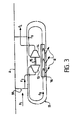
- Figures 2 and 3 are characterized with respect to the basic system illustrated in Figure 1 by comparable thermal performance, size and mass similar, even lower, and reduced acquisition cost.
Landscapes
- Health & Medical Sciences (AREA)
- General Health & Medical Sciences (AREA)
- Pulmonology (AREA)
- Engineering & Computer Science (AREA)
- Aviation & Aerospace Engineering (AREA)
- Structures Of Non-Positive Displacement Pumps (AREA)
- Cooling Or The Like Of Electrical Apparatus (AREA)
- Motor Or Generator Cooling System (AREA)
- Details Of Measuring And Other Instruments (AREA)
Applications Claiming Priority (2)
| Application Number | Priority Date | Filing Date | Title |
|---|---|---|---|
| FR9005901 | 1990-05-11 | ||
| FR9005901A FR2661888B1 (fr) | 1990-05-11 | 1990-05-11 | Methode pour le conditionnement thermique des equipements electroniques montes sur les aeronefs et systemes pour sa mise en óoeuvre. |
Publications (2)
| Publication Number | Publication Date |
|---|---|
| EP0456549A1 true EP0456549A1 (de) | 1991-11-13 |
| EP0456549B1 EP0456549B1 (de) | 1996-01-03 |
Family
ID=9396518
Family Applications (1)
| Application Number | Title | Priority Date | Filing Date |
|---|---|---|---|
| EP91401115A Expired - Lifetime EP0456549B1 (de) | 1990-05-11 | 1991-04-26 | Verfahren zur Klimatisierung der elektronischen Einrichtungen eines Flugzeuges und Einrichtungen dafür |
Country Status (5)
| Country | Link |
|---|---|
| US (1) | US5201182A (de) |
| EP (1) | EP0456549B1 (de) |
| JP (1) | JPH0524587A (de) |
| DE (1) | DE69115982T2 (de) |
| FR (1) | FR2661888B1 (de) |
Cited By (1)
| Publication number | Priority date | Publication date | Assignee | Title |
|---|---|---|---|---|
| EP0738655A3 (de) * | 1995-04-20 | 1998-01-21 | British Aerospace Public Limited Company | Klimaregelungssystem |
Families Citing this family (17)
| Publication number | Priority date | Publication date | Assignee | Title |
|---|---|---|---|---|
| JP2666902B2 (ja) * | 1993-03-10 | 1997-10-22 | 松下電器産業株式会社 | 除湿装置 |
| DE29702259U1 (de) * | 1996-02-12 | 1997-06-19 | Cappelmann, Wilfried H., 27574 Bremerhaven | Klimagerät zum Zuführen klimatisierter Luft beispielsweise zu einem am Boden befindlichen Flugzeug |
| JP2001521812A (ja) * | 1997-11-04 | 2001-11-13 | プノイマーティク ベルリン ゲー エム ベー ハー | ガス回収用の方法及び装置 |
| GB0029194D0 (en) * | 2000-11-30 | 2001-01-17 | Honeywell Normalair Garrett | Cooling apparatus |
| EP1438537A4 (de) * | 2001-09-21 | 2005-04-13 | Collins & Aikman Automotive Co | Nichtmechanisches gebläse |
| US6908702B2 (en) * | 2002-05-03 | 2005-06-21 | Ion America Corporation | Fuel cell for airship power generation and heating |
| DE102006046114B4 (de) | 2006-09-28 | 2012-02-02 | Airbus Operations Gmbh | Kühlanordnung zur Kühlung eines Wärmekörpers für ein Luftfahrzeug |
| US20110219786A1 (en) * | 2010-03-11 | 2011-09-15 | Andres Michael J | Fluid heat sink powered vapor cycle system |
| EP2691251B1 (de) | 2011-03-28 | 2018-05-09 | Rolls-Royce North American Technologies, Inc. | Flugzeug sowie luftstrom- und wärmeverwaltungssystem |
| WO2012135314A1 (en) | 2011-03-29 | 2012-10-04 | Rolls-Royce North American Technologies Inc. | Vehicle system |
| US9908635B2 (en) | 2013-03-15 | 2018-03-06 | Rolls-Royce North American Technologies Inc. | Aircraft system |
| DE102015122739B4 (de) * | 2015-12-23 | 2019-04-25 | Dr. Neumann Peltier-Technik Gmbh | Kühlvorrichtung mit Peltier-Element |
| CN205316736U (zh) * | 2015-12-25 | 2016-06-15 | 广州亿航智能技术有限公司 | 多轴载人飞行器 |
| CN205440884U (zh) * | 2015-12-25 | 2016-08-10 | 广州亿航智能技术有限公司 | 多轴载人飞行器 |
| US10455740B1 (en) | 2018-07-19 | 2019-10-22 | Ge Aviation Systems Llc | Electronic chassis with heat exchanger |
| RU2731043C2 (ru) * | 2019-01-09 | 2020-08-28 | Российская Федерация, от имени которой выступает федеральное государственное казенное учреждение "Управление авиации Федеральной службы безопасности Российской Федерации" | Контейнер авиационный подвесной с полезной нагрузкой |
| US12528589B2 (en) * | 2022-08-04 | 2026-01-20 | Hamilton Sundstrand Corporation | RAM air cooling power recovery |
Citations (5)
| Publication number | Priority date | Publication date | Assignee | Title |
|---|---|---|---|---|
| US2477931A (en) * | 1947-01-06 | 1949-08-02 | Garrett Corp | Evaporative cooling system for aircraft having expansion means |
| US2503250A (en) * | 1948-06-02 | 1950-04-11 | Ernst R G Eckert | Air conditioning apparatus for high-speed aircraft |
| US2721456A (en) * | 1953-07-14 | 1955-10-25 | Fairchild Engine & Airplane | Aircraft air conditioning system |
| EP0342166A2 (de) * | 1988-05-13 | 1989-11-15 | Urbano Barbabella | Wärmekonditionierungsgerät mit mindestens einem thermo-elektrischen Modul mit umkehrbarer thermo-elektrischer Wirkung |
| DE3824468A1 (de) * | 1988-07-19 | 1990-01-25 | Messerschmitt Boelkow Blohm | Verfahren zur bereitstellung von mechanischer leistung und kuehlluft in hyperschallfluggeraeten |
Family Cites Families (7)
| Publication number | Priority date | Publication date | Assignee | Title |
|---|---|---|---|---|
| USRE24179E (en) * | 1956-07-10 | Electric generating and air cooling system | ||
| US2473496A (en) * | 1944-10-11 | 1949-06-14 | Garrett Corp | Air conditioning system |
| US2786341A (en) * | 1950-06-19 | 1957-03-26 | Garrett Corp | Direct evaporative vortex tube refrigeration system |
| US2839900A (en) * | 1950-08-31 | 1958-06-24 | Garrett Corp | Regenerative vortex cooling systems |
| US3236056A (en) * | 1965-01-11 | 1966-02-22 | Edward L Phillips | Apparatus for cooling automobiles and the like |
| US4209993A (en) * | 1978-03-06 | 1980-07-01 | United Technologies Corp. | Efficiency air cycle environmental control system |
| JPH0285010A (ja) * | 1988-06-25 | 1990-03-26 | Nippon Denso Co Ltd | 冷房装置 |
-
1990
- 1990-05-11 FR FR9005901A patent/FR2661888B1/fr not_active Expired - Fee Related
-
1991
- 1991-04-22 US US07/689,375 patent/US5201182A/en not_active Expired - Fee Related
- 1991-04-26 DE DE69115982T patent/DE69115982T2/de not_active Expired - Fee Related
- 1991-04-26 EP EP91401115A patent/EP0456549B1/de not_active Expired - Lifetime
- 1991-05-13 JP JP3135261A patent/JPH0524587A/ja not_active Withdrawn
Patent Citations (5)
| Publication number | Priority date | Publication date | Assignee | Title |
|---|---|---|---|---|
| US2477931A (en) * | 1947-01-06 | 1949-08-02 | Garrett Corp | Evaporative cooling system for aircraft having expansion means |
| US2503250A (en) * | 1948-06-02 | 1950-04-11 | Ernst R G Eckert | Air conditioning apparatus for high-speed aircraft |
| US2721456A (en) * | 1953-07-14 | 1955-10-25 | Fairchild Engine & Airplane | Aircraft air conditioning system |
| EP0342166A2 (de) * | 1988-05-13 | 1989-11-15 | Urbano Barbabella | Wärmekonditionierungsgerät mit mindestens einem thermo-elektrischen Modul mit umkehrbarer thermo-elektrischer Wirkung |
| DE3824468A1 (de) * | 1988-07-19 | 1990-01-25 | Messerschmitt Boelkow Blohm | Verfahren zur bereitstellung von mechanischer leistung und kuehlluft in hyperschallfluggeraeten |
Non-Patent Citations (2)
| Title |
|---|
| ENGINEERING. (INCL. MACHINE SHOP MAGAZINE) vol. 222, no. 5, mai 1982, LONDON GB pages 348 - 349; R. AXE: "TAKING THE HEAT OUT OF AVIONICS", "System Layout";figure 1. * |
| PATENT ABSTRACTS OF JAPAN vol. 14, no. 277 (M-985)(4220) 15 juin 1990, & JP-A-02 85010 (NIPPON DENSO CO) 26 mars 1990, * |
Cited By (2)
| Publication number | Priority date | Publication date | Assignee | Title |
|---|---|---|---|---|
| EP0738655A3 (de) * | 1995-04-20 | 1998-01-21 | British Aerospace Public Limited Company | Klimaregelungssystem |
| US5860283A (en) * | 1995-04-20 | 1999-01-19 | British Aerospace Public Limited Company | Environmental control system |
Also Published As
| Publication number | Publication date |
|---|---|
| US5201182A (en) | 1993-04-13 |
| DE69115982D1 (de) | 1996-02-15 |
| JPH0524587A (ja) | 1993-02-02 |
| DE69115982T2 (de) | 1996-05-30 |
| FR2661888B1 (fr) | 1996-12-13 |
| FR2661888A1 (fr) | 1991-11-15 |
| EP0456549B1 (de) | 1996-01-03 |
Similar Documents
| Publication | Publication Date | Title |
|---|---|---|
| EP0456549A1 (de) | Verfahren zur Klimatisierung der elektronischen Einrichtungen eines Flugzeuges und Einrichtungen dafür | |
| CA2546685C (fr) | Systeme de refroidissement d'un fluide d'un aeronef et aeronef equipe d'un tel systeme | |
| CA2929951C (fr) | Ensemble propulsif d'aeronef avec systeme d'extinction de feu | |
| CA2562496A1 (fr) | Dispositif et procede de generation de thermies a materiau magneto-calorique | |
| CA2619146A1 (fr) | Dispositif de refroidissement d'un equipement electrique dans une turbomachine | |
| FR2557204A1 (fr) | Dispositif de refroidissement d'un composant de turbomoteur | |
| CA2924411A1 (fr) | Turbomachine adaptee a fonctionner en mode vireur | |
| EP2112347B1 (de) | Kühlmittelkreislauf eines Motors | |
| EP0780254A1 (de) | Fahrzeugzusatzheizung unter Verwendung des Klimakreislaufes | |
| EP0595713B1 (de) | Verfahren und Anlage zur Klimatisierung eines Fahrzeugs, insbesondere eines Elektrofahrzeugs | |
| FR2986905A1 (fr) | Procede de refroidissement de composants electroniques dans un turboreacteur d'aeronef | |
| FR3081514A1 (fr) | Ensemble propulsif d'aeronef et procede de reduction d'un debit d'air de ventilation dans l'ensemble propulsif d'aeronef | |
| FR2982319A1 (fr) | Systeme de commande d'une vanne pneumatique de turbomachine | |
| FR2913402A1 (fr) | Aeronef comportant un systeme de conditionnement d'air. | |
| FR3096071A1 (fr) | Contrôle de jeu entre des aubes de rotor d’aéronef et un carter | |
| EP0473494A1 (de) | Brennstoffversorgungssystem für einen Turbomotor | |
| CA3137701A1 (fr) | Turbomachine comprenant un systeme de degivrage du cone amont, et procede associe | |
| FR2968718A1 (fr) | Turboreacteur comprenant un circuit de prelevement d'air de refroidissement a variation de debit automatique | |
| EP3414438B1 (de) | Ladeluftversorgung für eine brennkraftmaschine | |
| FR2742605A1 (fr) | Alternateur refroidi par air et liquide avec dispositif de regulation de debit d'air | |
| FR3081509A1 (fr) | Moteur d'aeronef avec controle thermique de la veine du compresseur et procede pour ledit controle thermique | |
| FR2698433A1 (fr) | Systèmes de climatisation à cycle d'air. | |
| EP3412976A1 (de) | Heizsystem zum beheizen der räume einer wohnung, das ein hauptheizgerät und eine luftverteilungsanlage umfasst | |
| FR2469560A1 (fr) | Dispositif de commande de la soupape de regulation des gaz d'echappement sur moteur suralimente equipe d'un regulateur de vitesse | |
| FR2761459A1 (fr) | Systeme de securite pour bruleurs d'appareil de cuisson |
Legal Events
| Date | Code | Title | Description |
|---|---|---|---|
| PUAI | Public reference made under article 153(3) epc to a published international application that has entered the european phase |
Free format text: ORIGINAL CODE: 0009012 |
|
| AK | Designated contracting states |
Kind code of ref document: A1 Designated state(s): DE GB IT |
|
| 17P | Request for examination filed |
Effective date: 19911220 |
|
| 17Q | First examination report despatched |
Effective date: 19930521 |
|
| RAP1 | Party data changed (applicant data changed or rights of an application transferred) |
Owner name: THOMSON-CSF |
|
| GRAA | (expected) grant |
Free format text: ORIGINAL CODE: 0009210 |
|
| AK | Designated contracting states |
Kind code of ref document: B1 Designated state(s): DE GB IT |
|
| ITF | It: translation for a ep patent filed | ||
| REF | Corresponds to: |
Ref document number: 69115982 Country of ref document: DE Date of ref document: 19960215 |
|
| GBT | Gb: translation of ep patent filed (gb section 77(6)(a)/1977) |
Effective date: 19960311 |
|
| PLBE | No opposition filed within time limit |
Free format text: ORIGINAL CODE: 0009261 |
|
| STAA | Information on the status of an ep patent application or granted ep patent |
Free format text: STATUS: NO OPPOSITION FILED WITHIN TIME LIMIT |
|
| 26N | No opposition filed | ||
| REG | Reference to a national code |
Ref country code: GB Ref legal event code: IF02 |
|
| PGFP | Annual fee paid to national office [announced via postgrant information from national office to epo] |
Ref country code: GB Payment date: 20050420 Year of fee payment: 15 |
|
| PGFP | Annual fee paid to national office [announced via postgrant information from national office to epo] |
Ref country code: DE Payment date: 20050421 Year of fee payment: 15 |
|
| PG25 | Lapsed in a contracting state [announced via postgrant information from national office to epo] |
Ref country code: GB Free format text: LAPSE BECAUSE OF NON-PAYMENT OF DUE FEES Effective date: 20060426 |
|
| PGFP | Annual fee paid to national office [announced via postgrant information from national office to epo] |
Ref country code: IT Payment date: 20060430 Year of fee payment: 16 |
|
| PG25 | Lapsed in a contracting state [announced via postgrant information from national office to epo] |
Ref country code: DE Free format text: LAPSE BECAUSE OF NON-PAYMENT OF DUE FEES Effective date: 20061101 |
|
| GBPC | Gb: european patent ceased through non-payment of renewal fee |
Effective date: 20060426 |
|
| PG25 | Lapsed in a contracting state [announced via postgrant information from national office to epo] |
Ref country code: IT Free format text: LAPSE BECAUSE OF NON-PAYMENT OF DUE FEES Effective date: 20070426 |