EP0456564B1 - Direction assistée et système pour le glissement limité du différentiel - Google Patents
Direction assistée et système pour le glissement limité du différentiel Download PDFInfo
- Publication number
- EP0456564B1 EP0456564B1 EP91401174A EP91401174A EP0456564B1 EP 0456564 B1 EP0456564 B1 EP 0456564B1 EP 91401174 A EP91401174 A EP 91401174A EP 91401174 A EP91401174 A EP 91401174A EP 0456564 B1 EP0456564 B1 EP 0456564B1
- Authority
- EP
- European Patent Office
- Prior art keywords
- steering
- pressure
- pressure oil
- cylinder
- air
- Prior art date
- Legal status (The legal status is an assumption and is not a legal conclusion. Google has not performed a legal analysis and makes no representation as to the accuracy of the status listed.)
- Expired - Lifetime
Links
- 230000004044 response Effects 0.000 claims description 58
- 238000006243 chemical reaction Methods 0.000 claims description 45
- 238000002347 injection Methods 0.000 claims description 23
- 239000007924 injection Substances 0.000 claims description 23
- 230000007246 mechanism Effects 0.000 claims description 19
- 238000005452 bending Methods 0.000 claims description 10
- 230000008878 coupling Effects 0.000 claims description 9
- 238000010168 coupling process Methods 0.000 claims description 9
- 238000005859 coupling reaction Methods 0.000 claims description 9
- 238000011144 upstream manufacturing Methods 0.000 claims description 6
- 230000001965 increasing effect Effects 0.000 description 9
- 238000004088 simulation Methods 0.000 description 7
- 230000008859 change Effects 0.000 description 6
- 238000003825 pressing Methods 0.000 description 5
- 238000010586 diagram Methods 0.000 description 4
- 230000000694 effects Effects 0.000 description 4
- 230000001133 acceleration Effects 0.000 description 3
- 238000004364 calculation method Methods 0.000 description 3
- 230000009699 differential effect Effects 0.000 description 3
- 230000002708 enhancing effect Effects 0.000 description 3
- 238000011835 investigation Methods 0.000 description 3
- 230000009467 reduction Effects 0.000 description 3
- 239000000725 suspension Substances 0.000 description 3
- 206010021703 Indifference Diseases 0.000 description 2
- 230000003247 decreasing effect Effects 0.000 description 2
- 230000001934 delay Effects 0.000 description 2
- 238000007599 discharging Methods 0.000 description 2
- 238000000034 method Methods 0.000 description 2
- 238000004904 shortening Methods 0.000 description 2
- 238000012546 transfer Methods 0.000 description 2
- 241000239290 Araneae Species 0.000 description 1
- 238000013459 approach Methods 0.000 description 1
- 238000006757 chemical reactions by type Methods 0.000 description 1
- 238000004590 computer program Methods 0.000 description 1
- 238000012937 correction Methods 0.000 description 1
- 238000013016 damping Methods 0.000 description 1
- 238000006073 displacement reaction Methods 0.000 description 1
- 230000006870 function Effects 0.000 description 1
- 230000000977 initiatory effect Effects 0.000 description 1
- 239000000047 product Substances 0.000 description 1
- 230000035485 pulse pressure Effects 0.000 description 1
- 239000013589 supplement Substances 0.000 description 1
- 230000001629 suppression Effects 0.000 description 1
- 230000003746 surface roughness Effects 0.000 description 1
- 238000012795 verification Methods 0.000 description 1
Images


Classifications
-
- B—PERFORMING OPERATIONS; TRANSPORTING
- B60—VEHICLES IN GENERAL
- B60K—ARRANGEMENT OR MOUNTING OF PROPULSION UNITS OR OF TRANSMISSIONS IN VEHICLES; ARRANGEMENT OR MOUNTING OF PLURAL DIVERSE PRIME-MOVERS IN VEHICLES; AUXILIARY DRIVES FOR VEHICLES; INSTRUMENTATION OR DASHBOARDS FOR VEHICLES; ARRANGEMENTS IN CONNECTION WITH COOLING, AIR INTAKE, GAS EXHAUST OR FUEL SUPPLY OF PROPULSION UNITS IN VEHICLES
- B60K23/00—Arrangement or mounting of control devices for vehicle transmissions, or parts thereof, not otherwise provided for
- B60K23/04—Arrangement or mounting of control devices for vehicle transmissions, or parts thereof, not otherwise provided for for differential gearing
-
- B—PERFORMING OPERATIONS; TRANSPORTING
- B62—LAND VEHICLES FOR TRAVELLING OTHERWISE THAN ON RAILS
- B62D—MOTOR VEHICLES; TRAILERS
- B62D6/00—Arrangements for automatically controlling steering depending on driving conditions sensed and responded to, e.g. control circuits
- B62D6/04—Arrangements for automatically controlling steering depending on driving conditions sensed and responded to, e.g. control circuits responsive only to forces disturbing the intended course of the vehicle, e.g. forces acting transversely to the direction of vehicle travel
-
- B—PERFORMING OPERATIONS; TRANSPORTING
- B62—LAND VEHICLES FOR TRAVELLING OTHERWISE THAN ON RAILS
- B62D—MOTOR VEHICLES; TRAILERS
- B62D7/00—Steering linkage; Stub axles or their mountings
- B62D7/06—Steering linkage; Stub axles or their mountings for individually-pivoted wheels, e.g. on king-pins
- B62D7/14—Steering linkage; Stub axles or their mountings for individually-pivoted wheels, e.g. on king-pins the pivotal axes being situated in more than one plane transverse to the longitudinal centre line of the vehicle, e.g. all-wheel steering
- B62D7/15—Steering linkage; Stub axles or their mountings for individually-pivoted wheels, e.g. on king-pins the pivotal axes being situated in more than one plane transverse to the longitudinal centre line of the vehicle, e.g. all-wheel steering characterised by means varying the ratio between the steering angles of the steered wheels
- B62D7/159—Steering linkage; Stub axles or their mountings for individually-pivoted wheels, e.g. on king-pins the pivotal axes being situated in more than one plane transverse to the longitudinal centre line of the vehicle, e.g. all-wheel steering characterised by means varying the ratio between the steering angles of the steered wheels characterised by computing methods or stabilisation processes or systems, e.g. responding to yaw rate, lateral wind, load, road condition
Definitions
- This invention relates to a power steering and limited slip differential system suitable for vehicles, in particular, for trucks and buses.
- phase lag and gain of a vehicle's handling response increase with vehicle speed. Excessive phase lag will cause delay in the vehicle reaching the driver's intended course, resulting in oversteering, while excessive gain will intensify the oversteering, making the vehicle weave.
- phase lag will also increase the time required for disturbance, such as road surface roughness, to be transmitted to the driver's hand on the steering wheel as a response, delaying corrective steering and producing steering wheel weave.
- disturbance such as road surface roughness
- the phase lag magnitude in particular can reach four or five times that of passenger cars.
- vehicle's controllability and stability have to be investigated from both sides, in that the vehicle response performance in association with driver's handling and the vehicle response performance in association with disturbances such as those caused by roughness of the road surface.
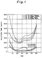
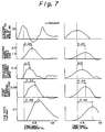
- Fig. 2 shows an example of the response characteristic of a truck and bus.
- the truck is equipped with a front engine and leaf suspensions, while the bus with a rear engine and air suspensions, and the gain and phase lag of the truck are smaller than those of the bus. Further the subjective judgement of the truck is better than the bus.
- phase lag is assumed to belong to the time constant property.
- approach to an aimed course by a driver delays so that an oversteering is caused, and when the gain is much larger, the oversteering is amplified so that the vehicle weaves.
- the problems arising from the physiological ability difference can be compensated by reducing the time constant in the steering system.
- the irregularity of the road surface causes displacement of the axles and the chassis in succession, such is sensed by the driver, and thereafter the driver's corrective steering begins.
- a smaller delay until the corrective steering and greater damping of the disturbances are desirable, however beyond this, if the disturbances can be intercepted at the inlet so as not to permit their entries, such is considered the best way.
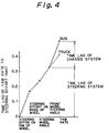
- the time lag in the steering system occupies 50% of the total. Further, with regard to the chassis system, the time lag of the buses is larger than that of trucks, the reasons of which are considered due to the influence of such as their suspension structure differences and weight allotment differences to the front and rear axles.
- truck and bus employ common steering systems so that with regard to the time lag in their steering systems there are no difference.
- the disturbances be intercepted at the inlet.
- the countermeasures thereto are the compliance steering control of the rear wheels and the torque split control between the right and left rear wheels, in particular, in case of the rigid rear axle structure with leaf springs which is employed in many large commercial vehicles, the torque split control is preferable.
- US Patent N°. 4, 796, 714 shows a power steering system in which an auxiliary booster is driven simultaneously with a main booster when a large vehicle is at a stop or is running at low speed, and assumes a free state when the vehicle is running at high speed. This system does not enhance handling response performance and disturbance response performance to enhance the control stability of the vehicle.
- the pressure of the compensating pressure oil which is injected into the reaction chambers of the directional control valve and the auxiliary booster is increased by the injection pressure control valve in response to the rise of the vehicle speed and the increase of the differential value in the steering effort to perform compensation for the steering delay in the handling which reduces the phase lag without increasing the gain
- the air pressure of the clutch control air cylinder, with the air pressure control valve is reduced in response to the increase of the vehicle speed and the increase of the front wheel steering angle in a low speed region, is raised in response to the increase of the vehicle speed and the decrease of the front wheel steering angle in a high speed region, is raised in response to the slip of one side of the rear wheels in a low vehicle speed, and is reduced in response to the slip of the both sides of the rear wheels in a low vehicle speed so as to limit differential action and to increase and decrease driving force which suppress interference to the running along the course of the vehicle, help escape the vehicle from the road surface having a small road surface
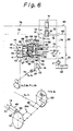
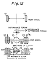
- Figs. 6, 13, 14, 15, 16 and 17 show the concrete embodiment of the power steering and limited slip differential system 10 according to the present invention which is applied to a rear-mounted engine bus.
- the system 10 is composed of a power steering arrangement 11 and a limited slip differential arrangement 12,
- the power steering arrangement 11 includes such as a main booster 14, an auxiliary booster 15, a directional control valve 16, a pressure oil setting valve 17, an injection pressure control valves 18, 19, a reaction adjusting valve 20, a hydraulic pump 21 provided with an oil reservoir, and a steering wheel 23 which provides a steering input to the directional control valve 16,
- the limited slip differential arrangement 12 includes such as a differential gear mechanism 25 combined with a reduction gear mechanism 91, a friction clutch 26, a clutch control air cylinder 27, an air pressure control valve 28, an air tank 29, and a safety valve 30, and the power steering arrangement 11 and limited slip differential arrangement 12 are assembled to facilitate an electronic control with a microcomputer 13.
- the microcomputer 13 electrically connects at its input side with a vehicle speed sensor 31, a steering effort sensor 32, a wheel rotation sensors 33, 34, 35, 36, a pressure sensor 37, a manual switch 38 and a brake switch 39 and electrically connects at its output side with the solenoid coils (not shown) of the injection pressure control valves 18, 19, the electric actuator (not shown) of the air pressure control valve 28 respectively, controls the power steering arrangement 11 so as to perform a steering operation in which a steering delay compensation is added which reduces the phase lag without increasing the gain, and as well as controls the limited slip differential arrangement 12 so as to limit the differential action and to increase and decrease the driving force (transferred torque), further, concurrently, with the power steering arrangement 11 to lighten the power steering effort during stationary steering and a low speed running, and to change the handling response feeling into a level of somewhat heavier steering effort during a high speed running.
- the main booster 14 incorporates the directional control valve 16, generates steering effort for front wheels 121, 122 and is constructed into an integral type which enables manual steering.
- the main booster 14 includes a cylinder body 40 inside of which a cylinder bore 41 is formed, a rack piston 42 fitted in the cylinder bore 41 permitting slidable reciprocation to form a pair of cylinder chambers 43, 44 in the cylinder bore 41 and a sector gear (not shown) engaging the rack of the rack piston 42, and is link-coupled to the front wheels 121, 122 via a pitman arm 45 fixedly coupled to the shaft (not shown) of the sector gear and a link mechanism 46, of course, oil ports 47, 48 which open to the corresponding cylinder chambers 43, 44 are formed at the cylinder body 40.
- the auxiliary booster 15 is constructed into a double acting type cylinder which generates an auxiliary steering effort for the front wheels 121, 123.
- the auxiliary booster 15 includes a cylinder body 49 inside of which a cylinder bore (not shown) is formed, a piston (not shown) fitted in the cylinder bore permitting slidable reciprocation to form a pair of cylinder chambers (not shown) in the cylinder bore, and a piston rod 50 one end of which is fixedly connected to the piston and the other end of which extends out of the cylinder body permitting pulling in and out thereof, and the other end of the piston rod 50 is link-coupled to the front wheels 121, 122 via link mechanism 46a.
- oil ports 51, 52 which open to the corresponding pair of cylinder chambers are formed at the cylinder body 49.
- the directional control valve 16 is provided with a pair of reaction chambers 56, 57, is incorporated into the cylinder body 40 of the main booster 14, and is constructed into a hydraulic reaction type spool valve in which a spool 55 is shifted by a shift shaft (not shown) secured to the input axis (not shown) which is connected to the steering shaft 24, and the operating pressure oil is direction-controlled which is supplied from the hydraulic pump 21 to the main booster 14 via a supply side pressure oil piping 74 and concurrently is exhausted from the main booster 14 to the oil reservoir 22 via a return side oil pressure piping 75.
- the directional control valve 16 includes a valve body 53 inside of which a valve bore 54 is provided and incorporated into the cylinder body 40 of the main booster 14, the spool 55 fitted in the valve bore 54 permitting slidable reciprocation to form the pair of reaction chambers 56, 57, and the spool 55 is slidably moved inside the valve bore 54 by the steering wheel 23 via the steering shaft 24, input axis, and the shift shaft and direction-controls the operating pressure oil so as to flow from the hydraulic pump 21 to either of the cylinder chambers 43, 44 in the main booster 14 via the supply side pressure oil piping 74 and concurrently from another of the cylinder chambers 43, 44 in the main booster 14 to the oil reservoir 22 via the returning pressure oil piping 75 respectively, and in that instance, the amount of steering in the main booster 14 is fed back.
- a pump port 58, tank ports 59, 60, cylinder ports 61, 62, reaction ports 63, 64, and injection ports 65, 66 which open to the valve bore 54 are formed at predetermined positions, the pump port 58 is connected to the supply side pressure oil piping 74 and the tank ports 59, 60 to the returning side pressure oil piping 75 respectively and further, the cylinder ports 61, 62 are connected to the corresponding oil ports 47, 48 via communicating channels 67, 68.
- reaction communicating ports 69, 70 are formed which supply the operating pressure oil into either of the reaction chambers 56, 57 from the hydraulic pump 21 in response to the shift direction of the spool 55 and as well as return the operating pressure oil from another of the reaction chambers 56, 57 to the oil reservoir 22, when the spool 55 is shifted within the valve bore 54.
- the pressure oil setting valve 17 is disposed in the supply side pressure oil piping 74 at the upstream side of the directional control valve 16, and sets the pressure of the operating pressure oil supplied to the main booster 14 and the pressure of the compensating pressure oil supplied to the auxiliary booster 15 and the chambers 56, 57 of the directional control valve 16.
- the injection pressure control valves 18, 19 are linear solenoid valves and are disposed in compensating pressure oil pipings 76, 77, 78, 79, 80, 81, 82, 83 which connect the pair of cylinder chambers of the auxiliary booster 15 and the pair of reaction chambers of the directional control valve 16 to the hydraulic pump 21 and the oil reservoir 22, and further, the solenoid coils (not shown) thereof are electrically connected to the output side of the microcomputer 13.
- the injection pressure control valves 18, 19 carry out valve operation by the current provided from the microcomputer 13 in response to the running speed of the bus and steering effort applied to the steering wheel 23 at the beginning of steering and of steering back, and at the beginning of steering inject the compensating pressure oil into the cylinder chambers of the auxiliary booster 15 and the reaction chambers 56, 57 of the directional control valve 16 in their predetermined direction, and at the time of steering back inject the compensating pressure oil into the cylinder chambers of the auxiliary booster 15 and the reaction chambers 56, 57 of the directional control valve 16 in their predetermined direction, and as well control the pressure of the compensating pressure oil injected.
- the injection pressure control valves 18, 19 connect the cylinder chambers of the auxiliary booster 15 to the oil reservoir 22 and as well interrupts the reaction chambers of the directional control valve 16 from the hydraulic pump 21 and the oil reservoir 22.
- injection pressure control valves 18, 19 have such a structure that the compensating pressure oil is injected into the cylinder chambers of the auxiliary booster 15 and the reaction chambers 56, 57 of the directional control valve 16, orifices 71, 72 are disposed in the compensating pressure oil pipings 80, 81 in view of the relationship between the cylinder chambers of the auxiliary booster 15 and the reaction chambers 56, 57 of the directional control valve 16.
- the reaction adjustment valve 20 is disposed in a bypass channel 73 communicating each other the pair of reaction chambers 56, 57 of the directional control valve 16, and the electric actuator thereof is electrically connected to the microcomputer 13.
- the electric actuator is driven by the current provided by the microcomputer 13, and the orifice thereof is adjusted so as to change the handling response in such a manner that the steering effort is felt lighter during a stationary steering and a low speed running and the steering effort is felt heavier during a high speed running.
- the differential gear mechanism 25 is incorporated with the reduction gear mechanism 91 which includes a drive pinion 92 and a ring gear 93 engaged each other in the differential carrier 84, and includes four differential pinions 88, 88 and a pair of differential side gears 89, 89 disposed in a differential case 86 in association with the reduction gear mechanism.
- the differential pinions 88, 88 are rotatably fitted at the both ends of spider 90, on the other hand, the differential side gears 89, 89 are spline-connected to driving wheel axles 119, 120 for the rear wheels 123, 124 and are engaged with the differential pinions 88, 88.
- the friction clutch 26 is disposed between the differential case 86 and the driving wheel axle 119, and is assembled to include the bore 94 formed in the differential case 86, clutch ring 96 forming the bore 94 of the differential case 86 spline-connected to the driving wheel axle 119 into a ring chamber 95, many external gear clutch plates 97 and internal gear clutch plates 98 alternatively arranged in the ring chamber 95 and a pressure ring 99 pushing the external and internal gear clutch plates 97, 98.
- this friction clutch 26 is assembled in a position in which the external gear clutch plates 97 is spline-coupled with the differential case 86, and the internal gear clutch plates 98, with the clutch ring 96 respectively, the differential action of the differential gear mechanism is limited and the transfer torque of the driving wheel axles 119, 120 is controlled in increasing and decreasing direction.
- the clutch control air cylinder 27 is incorporated into the differential case 86, and connected to the air tank 29 via pressurized air piping 111, and controls the friction clutch 26 to engage and disengage by charging and discharging the operating pressurized air supplied from the air tank 29.
- This clutch control air cylinder 27 is embodied into an internal cylinder guiding type structure which includes a ring cylinder 100 which opens to the ring chamber 95 and is formed in the differential case 86, and a ring piston 102 which is fitted in the ring cylinder 100 while facing to the pressure ring 99 and permitting slidable reciprocation to form cylinder chamber 101 in the ring cylinder 100, and is assembled in such a manner that an air port 103 which opens to the cylinder chamber 101 is connected to the pressurized air piping 111 via a pressure air coupling 104, the operating pressurized air is charged from the air tank 29 to the cylinder chamber 101 and discharged from the cylinder chamber 101 to the air and by pressing and separating the external and internal gear clutch plates 97, 98 via the pressure ring 99, the clutch engagement and disengagement operation of the friction clutch 26 is carried out.
- the pressure air coupling 104 is assembled together with a sealed slip ring 105 fitted onto a boss 87 of the differential case 86 so as to permit relative rotational movement thereto and fitted into a ring gear boss 85 of a differential carrier 84 so as to prevent rotation thereto, and an air lead pipe 106 connecting the shield slip ring 105 to the pressurized air piping 111 outside the differential carrier 84, and further the air lead pipe 106 comprises a pipe connector 107 and is connected to the pressurized air piping 111 via the pipe connector 107.
- the air pressure control valve 28 is disposed in the pressurized air piping 111 which connects clutch control air cylinder 27 with the air tank 29, is driven by the current provided from the microcomputer 13 in response to the vehicle speed and the front wheel steering angle, and in response to the slipping at one side and both sides of the rear wheels, charges and discharges the operating compressed air to and from the clutch control air cylinder 27, and controls the air pressure of the clutch control air cylinder 27.
- This air pressure control valve 28 is formed of a combination of a normally closed type two way solenoid valve 109 and normally open type two way solenoid valve 110, in particular, the normally open type two way solenoid valve 110 is disposed downstream the normally closed type two way solenoid valve 109 and is combined therewith each other, further the solenoid coils (not shown) of the normally closed type and normally open type two way solenoid valves 109 and 110 are electrically connected to the output side of the microcomputer 13.
- the normally closed type two way solenoid valve 109 is used for supplying the operating compressed air from the air tank 29 to the clutch control air cylinder 27, on the other hand, the normally open type two way solenoid valve 110 is for discharging the operating compressed air from the clutch control air cylinder 27 to the air.
- the vehicle speed sensor 31 is disposed at the diesel engine (not shown) mounted on the bus.
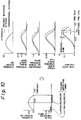
- the steering effort sensor 32 is for detecting the force applied to the steering wheel 23, and is incorporated in the steering wheel.
- the steering effort sensor 32 includes a bending beam of which root portion is secured at the side of the rim core 113 and the top portion is fitted into a groove 118 at the side of the rim sheath 115 so as to represent the sliding amount by bending, and an-electromagnetic inductor type sensor (not shown) for detecting the bending of the bending beam 117, and the electromagnetic inductor type sensor is electrically connected to the input side of the microcomputer 13.
- the wheel rotation sensors 33, 34, 35, 36 are respectively disposed corresponding to the front wheels and the rear wheels, and are electrically connected to the microcomputer 13.
- the pressure sensor 37 is combined with the air pressure control valve 28 at the position where the air pressure of the clutch control air cylinder 27 can be sensed, and is electrically connected to the microcomputer 13.
- the pressure oil namely, the compensating pressure oil be supplied to the power cylinder not only at the beginning of steering but also at the time of steering back in the form of pulse like pressure oil, if it were supplied at the beginning of steering only, the gain would deteriorate, namely increase (see Fig. 9).
- the pulse width and the pulse pressure of the pulse like pressure oil in response to both variations of the steering effort applied to the steering wheel and the differential value thereof, and the indifference of the steering operation is eliminated by applying the pulse like pressure oil correspondingly to the reaction chambers of the directional control valve.
- the vehicle speed is detected from the front wheel revolution speed, the steering angle from the revolution speed difference between the right and left front wheels and the slip rate of the rear wheels from the revolution speed difference between the front and rear wheels, based upon the detected values, the torque Td is controlled so as to increase with vehicle speed in a small steering angle region for enhancing stable straight running, and to be zero so as to maintain the lateral force gripping of the tires in the spin limit, and is further controlled so as to increase when one side of the rear wheels happens to slip, and to decrease when both sides of the rear wheels happen to slip, in order to improve prompt start performance on the road having a small road surface friction coefficient ⁇ and to reduce side slip.
- Fig. 14 The structure of the steering system is shown in Fig. 14 the upstream pressure is always kept higher by 5 Kg/cm 2 (pressurized oil) than that in the circuit with the pressure oil setting valve 17.
- the steering effort applied to the rim sheath 115 of the steering wheel 23 is calculated by the microcomputer 13 based on the bending and the spring constant of the bending beam 117.
- the electromagnetic inductor type sensor built-in in the steering wheel 23 detects thereof, the injection pressure control valves 18, 19 are selectively opened by the current selectively provided from the microcomputer 13, the compensating pressure oil is selectively injected into the pair of cylinder chambers of the auxiliary booster 15 and the actual steering of the front wheels 121, 122 begins while bypassing the system.
- the compensating pressure oil is also injected into the reaction chambers 56, 57 of the directional control valve 16, through the supply of this compensating pressure oil to the auxiliary booster 15, the steering indifference caused by the pull from the steering wheel 23 is prevented.
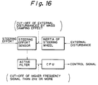
- the steering effort sensor 32 being located at a closer position to the driver than the rim core 113 which is the inertia mass of the steering wheel 23, detects the true steering effort without being affected by the inertia and as well is adapted to respond only to the steering effort by the driver through constitution unlike by to be affected by high frequency disturbances such as kick-back by means of the mass-damper effect of the rim core 113 and high response active low pass filter provided in the side of the microcomputer 13 (see Fig. 16).
- the structure of the differential system is shown in Fig. 17, in this differential system, the friction clutch 26 is incorporated in the differential case 86, and the clutch control air cylinder 27 is also disposed in the differential case 86 in association with the friction clutch 26, and thereby with the operating compressed air supplied to the clutch control air cylinder 27 the ring piston 102 is pressed to the many external gear and internal gear clutch plates 97, 98 of the friction clutch 26 via the pressure ring 99 to generate the torque limiting the differential operation in the differential system.
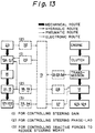
- the steering responsive control, the disturbance responsive control, and the speed sensitive control are carried out at the same time in association with each other.
- the steering effort sensor 32 detects the steering effort, and provides the steering effort in the form of an electrical signal to the microcomputer 13 and simultaneously the vehicle speed is provided in the form of an electrical signal from the vehicle speed sensor 31 to the microcomputer 13, accordingly, the microcomputer 13 controls the current flowing through the solenoid coils of the injection pressure control valves 18, 19 to selectively open and close the injection pressure control valves 18, 19 in response to the signals inputted from the steering effort sensor 32 and the vehicle speed sensor 31.
- the compensating pressure oil is selectively supplied to the pair of cylinder chambers of the auxiliary booster 15 from the upstream side of the pressure oil setting valve 17 in the front wheels, at the same time, the compensating pressure oil is selectively injected into the reaction chambers 56, 57 of the directional control valve 16 to generate the steering response, thereby controlling the increase of the yaw rate and the phase lag without increasing the gain during steering operation.
- the compensating pressure oil is supplied in the steering direction into the pair of cylinder chambers of the auxiliary booster 15 and the pair of reaction chambers of the directional control valve 16 in the form of pulse like pressure oil for a period of 0.075 wavelength from the beginning of the steering, and further, when the steering wheel 23 is steered back, the compensating pressure oil supplied in the steering back direction into the pair of cylinder chambers of the auxiliary booster 15 and the pair of reaction chambers of the directional control valve 16 in the form of pulse like pressure oil for a period of 0.25 wavelength from the beginning of the steering back.
- the disturbance responsive control is carried out based upon the vehicle speed, steering angle and rear wheel slip rate determined by the microcomputer 13.
- the wheel revolution sensors 33, 34, 35, 36 detect the revolution speed of the front wheels 121, 122 and the rear wheels 123, 124 and provide thereof to the microcomputer in the form of electrical signals, and then the microcomputer 13 calculates and determines the vehicle speed from the revolution speed of the front wheels, the steering angle from the revolution speed difference between the right and left front wheels, and the slip rate of the rear wheels 123, 124 from the revolution speed difference between the front wheels 121, 122 and the rear wheels 123, 124.
- the normal close type and normal open type two way solenoid valves 109, 110 in the air pressure control valve 28 are open and close controlled by the microcomputer 13 in response to the increase of the vehicle-speed, increase of the front wheel steering angle and the air pressure of the clutch control air cylinder 27, the operating compressed air is supplied from the air tank 29 to the clutch control air cylinder 27 and is discharged from the clutch control air cylinder 27 to the air to reduce the air pressure in the clutch control air cylinder, to lower the force of the clutch control air cylinder 27 pressing the friction clutch 26 and thereby to decrease the friction torque generated in the friction clutch 26 for limiting the differential movement of the differential gear mechanism 25.
- the differential movement limiting torque in the differential gear mechanism 25 is controlled to facilitate a smooth lane change by buses.
- the air pressure control valve 28 is open and close controlled by the microcomputer 13 as described above in response to the increase of the vehicle speed, increase of the front wheel steering angle and the air pressure of the clutch control air cylinder 27 to raise the air pressure in the clutch control air cylinder 27, to increase the force of the clutch control air cylinder pressing the friction clutch 26 and thereby to increase the friction torque generated in the friction clutch 26 for limiting the differential movement of the differential gear mechanism 25.
- the differential movement limiting torque in the differential gear mechanism 25 is controlled to stabilize the straight running of the bus and to maintain the lateral force gripping of the tire.
- the air pressure control valve 28 is open and close controlled by the microcomputer 13 to raise the air pressure in the clutch control air cylinder 27, to increase the force of the clutch control air cylinder 27 pressing the friction clutch 26 and thereby to increase the torque generated in the friction clutch 26 for limiting the differential movement of the differential gear mechanism 25.
- the air pressure control valve 28 is open and close controlled by the microcomputer 13 to lower the air pressure in the clutch control air cylinder 27, to reduce the force of the clutch control air cylinder 27 pressing the friction clutch 26 and thereby to decrease the torque generated in the friction clutch 26 for limiting the differential movement of the differential gear mechanism 25.
- the bus performs a smooth start and runs on the road having a low road surface friction coefficient ⁇ .
- the microcomputer 13 controls the current flowing through the electric actuator of the reaction adjustment valve 20 in response to the signals from the vehicle speed sensor 31, and adjusts the orifice of the reaction adjustment valve 20 in response to the increase of the vehicle speed to change the resistance to the pressure oil flowing between the reaction chambers 56, 57 of the directional control valve 16 and to thereby regulate the steering effort lighter during a stationary steering and a low speed running and somewhat heavier during a high speed running so as to obtain a sufficient handling response feeling.
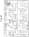
- Fig. 19 the gain and phase lag are illustrated in relation to the vehicle speed and the lateral acceleration.
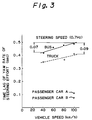
- Fig. 20 shows steering angles and their frequency on a highway.
- the steering angle frequency distribution of this system 10 is reduced above 50% in terms of standard deviation in comparison with that of the conventional system.
- the power steering and limited slip differential system includes a main booster which generates a steering effort for front wheels; an auxiliary booster which generates a compensation steering effort for the front wheels; a directional control valve which has pair of reaction chambers and which controls the direction of operating pressure oil which is supplied from a hydraulic pump to the main booster and concurrently discharged from the main booster to an oil reservoir; a pressure oil setting valve which sets the pressure of the operating pressure oil supplied to the main booster, and the pressure of compensating pressure oil supplied to the auxiliary booster and the reaction chambers of the directional control valve; an injection pressure control valve which injects the compensating pressure oil into the reaction chambers of the directional control valve and the auxiliary booster in response to a vehicle speed and the steering effort at the beginning of steering and steering back during the handling, and concurrently controls the pressure of the injected compensating pressure oil; a friction clutch disposed between the differential case of a differential gear mechanism and a driving wheel axle for rear wheels; a clutch control air cylinder for coupling and decoup
Landscapes
- Engineering & Computer Science (AREA)
- Chemical & Material Sciences (AREA)
- Combustion & Propulsion (AREA)
- Transportation (AREA)
- Mechanical Engineering (AREA)
- Mathematical Physics (AREA)
- Physics & Mathematics (AREA)
- Theoretical Computer Science (AREA)
- Steering Control In Accordance With Driving Conditions (AREA)
- Control Of Driving Devices And Active Controlling Of Vehicle (AREA)
- Power Steering Mechanism (AREA)
- Retarders (AREA)
- Motor Power Transmission Devices (AREA)
Claims (18)
- Système de direction assistée et de différentiel à glissement comprenant un amplificateur principal (14) qui génère un effort de braquage des roues avant (121, 122), une soupape de commande directionnelle (16) qui possède au moins une chambre (56, 57) et commande la direction de l'huile sous pression d'actionnement qui est envoyée depuis une pompe hydraulique (21) vers l'amplificateur principal (14) et évacuée concurremment de l'amplificateur principal (14) vers un réservoir d'huile (22), et un amplificateur auxiliaire (15) qui génère un effort de direction de compensation des roues avant (121, 122),
caractérisé en ce que
il comprend en outre un embrayage à friction (26) disposé entre le corps de différentiel (86) d'un mécanisme de différentiel (25) et un axe de roue motrice (119) pour les roues arrière (123, 124),
la soupape de commande directionnelle possède une paire de chambres de réaction (56, 57),
la pression de l'huile sous pression d'actionnement délivrée à l'amplificateur principal (14) et la pression de l'huile sous pression de compensation délivrée à l'amplificateur auxiliaire (15) et aux chambres de réaction (56, 57) de la soupape directionnelle (16) sont réglées par une soupape de réglage d'huile sous pression,
l'huile sous pression de compensation est injectée dans l'amplificateur auxiliaire (15) et les chambres de réaction (56, 57) de la soupape de commande directionnelle (16) en réponse à une vitesse du véhicule et à l'effort de braquage au début du braquage et du contre-braquage au moyen d'une soupape de commande de pression d'injection (18, 19) et concurremment, la pression de l'huile sous pression de compensation injectée est ainsi commandée,
l'engagement et le désengagement de l'embrayage à friction (26) sont réalisés par un vérin pneumatique de commande d'embrayage (27), et
l'air comprimé d'actionnement est chargé dans et déchargé du vérin pneumatique de commande d'embrayage (27) au moyen d'une soupape de commande de pression d'air (28) en réponse à la vitesse du véhicule et à l'angle de braquage des roues avant, et en outre en réponse au patinage d'un côté et des deux côtés des roues arrière (123, 124) de façon à commander la pression d'air dans le vérin pneumatique de commande d' embrayage (27). - Système de direction assistée et de différentiel à glissement limité selon la revendication 1, dans lequel ledit amplificateur auxiliaire (15) est relié par biellette à une biellette ou une articulation des roues avant (121, 122) par l'intermédiaire d'un mécanisme à biellette (46a).
- Système de direction assistée et de différentiel à glissement limité selon la revendication 1, dans lequel ledit amplificateur auxiliaire (15) est constitué sous la forme d'un cylindre du type à double effet ayant une paire de chambres de cylindre et est relié par biellette au côté d'articulation des roues avant au moyen d'un mécanisme à biellette (46a).
- Système de direction assistée et de différentiel à glissement limité selon l'une quelconque des revendications 1 à 3, dans lequel ladite soupape de commande directionnelle (16) comprend une conduite de dérivation (73) grâce à laquelle la paire de chambres de réaction (56, 57) communiquent l'une avec l'autre et une soupape de réglage de réaction (20) disposée dans la conduite de dérivation (73).
- Système de direction assistée et de différentiel à glissement limité selon la revendication 4, dans lequel ladite soupape de réglage de réaction (20) est ajustée sur le plan de son orifice d'une manière telle que l'effort de braquage est relativement plus faible pendant un braquage à l'arrêt et un déplacement à faible vitesse est sensiblement plus grand pendant un déplacement à grande vitesse.
- Système de direction assistée et de différentiel à glissement limité selon l'une quelconque des revendications 1 à 5, dans lequel ladite soupape de réglage d'huile sous pression (17) est disposée au niveau du côté amont de la soupape de commande directionnelle (16) dans une tuyauterie d'huile sous pression du côté alimentation (74) qui relie l'amplificateur principal (14) à la pompe hydraulique (21) par l'intermédiaire de la soupape de commande directionnelle (16) afin que la pression de l'huile sous pression de compensation amenée vers la paire de chambres de cylindre de l'amplificateur auxiliaire (15) et la paire de chambres de réaction (56, 57) de la soupape de commande directionnelle (16) soit toujours réglée plus élevée que celle dans le circuit de l'amplificateur principal (14).
- Système de direction assistée et de différentiel à glissement limité selon l'une quelconque des revendications 1 à 6, dans lequel ladite soupape de réglage d'huile sous pression (17) règle toujours la pression de l'huile sous pression de compensation à 5 kg/cm2 de plus que celle dans le circuit de l'amplificateur principal (14).
- Système de direction assistée et de différentiel à glissement limité selon l'une quelconque des revendications 1 à 7, dans lequel lesdites soupapes de commande de pression d'injection (18, 19) sont disposées entre la pompe hydraulique (21) qui se trouve en amont de la soupape de réglage d'huile sous pression (17) et le réservoir d'huile (22) qui se trouve en aval de l'amplificateur principal (14) dans des tuyauteries d'huile sous pression de compensation (76, 77, 78, 79, 80, 81, 82) qui relient de façon correspondante la paire de chambres de cylindre de l'amplificateur auxiliaire (15) et la paire de chambres de réaction (56, 57) de la soupape de commande directionnelle (16).
- Système de direction assistée et de différentiel à glissement limité selon la revendication 1, dans lequel lesdites soupapes de commande de pression d'injection (18, 19) sont des paires d'électrovannes linéaires, et la paire d'électrovannes linéaires est reliée de manière correspondante au niveau de la pompe hydraulique (21) qui se trouve en amont de la soupape de réglage d'huile sous pression (17) avec des tuyauteries d'huile sous pression auxiliaires qui relient la paire de chambres de cylindre de l'amplificateur auxiliaire (15) à la paire de chambres de réaction (56, 57) de la soupape de commande directionnelle (16) et au niveau du réservoir d'huile (22) qui se trouve en aval de l'amplificateur principal (14) avec les tuyauteries d'huile sous pression auxiliaires qui relient la paire de chambres de cylindre de l'amplificateur auxiliaire (15) à la paire de chambre de chambres de réaction (56, 57) de la soupape de commande directionnelle (16).
- Système de direction assistée et de différentiel à glissement limité selon l'une quelconque des revendications 1 à 9, dans lequel lesdites soupapes de commande de pression d'injection (18, 19) sont actionnées en délivrant l'huile sous pression de compensation sous la forme d'une impulsion d'huile sous pression au début du braquage et du contre-braquage.
- Système de direction assistée et de différentiel à glissement limité selon l'une quelconque des revendications 1 à 9, dans lequel lesdites soupapes de commande de pression d'injection (18, 19) sont actionnées en délivrant l'huile sous pression de compensation sous la forme d'une impulsion d'huile sous pression ayant une largeur d'impulsion allant de 0,1 à 0,25 longueur d'onde par rapport à la longueur d'onde d'effort de braquage au début du braquage et du contre-braquage.
- Système de direction assistée et de différentiel à glissement limité selon l'une quelconque des revendications 1 à 9, dans lequel lesdites soupapes de commande de pression d'injection (18, 19) sont alimentées avec l'huile sous pression de compensation sous la forme d'une impulsion d'huile sous pression au début du braquage et du contre-braquage et la largeur d'impulsion et l'amplitude d'impulsion de l'impulsion d'huile sous pression sont déterminées en réponse à la fois aux variations d'effort de braquage appliqué sur un volant de direction et à la valeur différentielle de celui-ci.
- Système de direction assistée et de différentiel à glissement limité selon l'une quelconque des revendications 1 à 12, dans lequel ledit vérin pneumatique de commande d'embrayage (27) comprend un cylindre annulaire (100) qui s'ouvre sur une chambre annulaire (95) et est formé dans le corps de différentiel (86), et un piston annulaire (102) qui est monté dans le cylindre annulaire (100) de façon à permettre un mouvement alternatif coulissant tout en faisant face au plateau de pression (99) de l'embrayage à friction (26) afin de former une chambre de cylindre (101) dans le cylindre annulaire (100).
- Système de direction assistée et de différentiel à glissement limité selon la revendication 13, dans lequel ledit vérin pneumatique de commande d'embrayage (27) comprend en outre un raccord d'air sous pression (104) qui relie la chambre de cylindre (101) à une source d'air sous pression (29) par l'intermédiaire d'une tuyauterie sous pression (111).
- Système de direction assistée et de différentiel à glissement limité selon la revendication 14, dans lequel ledit raccord d'air sous pression (104) comprend un joint d'étanchéité coulissant (105) monté sur un bossage (87) du corps de différentiel (86) de façon à permettre un moment rotatif relatif qui est arrêté par un bossage de couronne dentée (85) dans le carter de différentiel (84) supportant le corps de différentiel (86), et un tuyau d'arrivée d'air (106) reliant le joint d'étanchéité coulissant (105) à la conduite d'air sous pression (111).
- Système de direction assistée et de différentiel à glissement limité selon l'une quelconque des revendications 1 à 15, dans lequel ladite soupape de commande de pression d'air (28) comprend une électrovanne à deux voies du type normalement fermé (109) disposée dans la tuyauterie d'air sous pression (111) qui relie le vérin pneumatique de commande d'embrayage (27) au réservoir d'air (29), et une électrovanne à deux voies du type normalement ouvert (110) disposée dans la tuyauterie d'air sous pression (111) en aval de l'électrovanne à deux voies du type normalement fermé (109), et l'électrovanne à deux voies du type normalement fermé délivre l'air comprimé d'actionnement provenant du réservoir d'air (29) au vérin pneumatique de commande d'embrayage (27) lorsque l'électrovanne à deux voies du type normalement ouvert (110) est fermée et l'électrovanne à deux voies du type normalement ouvert (110) évacue l'air comprimé d'actionnement vers l'air libre depuis le vérin pneumatique de commande d'embrayage (27) lorsque l'électrovanne à deux voies du type normalement fermé (109) est fermée.
- Système de direction assistée et de différentiel à glissement limité selon l'une quelconque des revendications 1 à 15, dans lequel ladite soupape de commande de pression d'air (28) comprend une électrovanne à deux voies du type normalement fermé (109) et une électrovanne à deux voies du type normalement ouvert (110) assemblée d'un seul tenant avec l'électrovanne à deux voies du type normalement fermé (109) en aval de celle-ci, et l'électrovanne à deux voies du type normalement fermé (109) délivre l'air comprimé d'actionnement au vérin pneumatique de commande d'embrayage (27) et l'électrovanne à deux voies du type normalement ouvert (110) décharge l'air comprimé d'actionnement du vérin pneumatique de commande d'embrayage (27).
- Système de direction assistée et de différentiel à glissement limité selon l'une quelconque des revendications 1 à 17, comportant en outre un volant de direction (23) qui comprend une jante (113) intégrée à un moyeu (112) au moyen de branche (114) et une gaine (115) recouvrant la couronne (113) avec un galet (116) de façon à permettre une rotation librement coulissante dans une direction de braquage, et
un capteur d'effort de direction (32) qui comprend une lame de flexion dont la partie de base est fixée au niveau du côté de la jante (113) et la partie supérieure est montée dans une rainure (118) au niveau du côté de la gaine (115) de façon à représenter par flexion la valeur de coulissement entre la couronne (113) et la gaine (115) et un capteur du type inducteur électromagnétique détectant la flexion de la lame de flexion (117).
Applications Claiming Priority (2)
| Application Number | Priority Date | Filing Date | Title |
|---|---|---|---|
| JP117403/90 | 1990-05-07 | ||
| JP2117403A JP2649857B2 (ja) | 1990-05-07 | 1990-05-07 | パワー・ステアリング・アンド・リミッテッド・スリップ・ディファレンシャル・システム |
Publications (2)
| Publication Number | Publication Date |
|---|---|
| EP0456564A1 EP0456564A1 (fr) | 1991-11-13 |
| EP0456564B1 true EP0456564B1 (fr) | 1996-09-04 |
Family
ID=14710788
Family Applications (1)
| Application Number | Title | Priority Date | Filing Date |
|---|---|---|---|
| EP91401174A Expired - Lifetime EP0456564B1 (fr) | 1990-05-07 | 1991-05-03 | Direction assistée et système pour le glissement limité du différentiel |
Country Status (4)
| Country | Link |
|---|---|
| US (1) | US5301766A (fr) |
| EP (1) | EP0456564B1 (fr) |
| JP (1) | JP2649857B2 (fr) |
| DE (1) | DE69121764T2 (fr) |
Families Citing this family (25)
| Publication number | Priority date | Publication date | Assignee | Title |
|---|---|---|---|---|
| US5530648A (en) * | 1993-05-03 | 1996-06-25 | Ford Motor Company | Apparatus and method for adjusting suspension height to reduce vehicles steering effort |
| US5991675A (en) * | 1993-06-02 | 1999-11-23 | Honda Giken Kogyo Kabushiki Kaisha | Vehicle control system based on estimation of the driving skill of a vehicle operator |
| US5710704A (en) | 1994-11-25 | 1998-01-20 | Itt Automotive Europe Gmbh | System for driving stability control during travel through a curve |
| US5732379A (en) | 1994-11-25 | 1998-03-24 | Itt Automotive Europe Gmbh | Brake system for a motor vehicle with yaw moment control |
| US5711024A (en) | 1994-11-25 | 1998-01-20 | Itt Automotive Europe Gmbh | System for controlling yaw moment based on an estimated coefficient of friction |
| US5732377A (en) | 1994-11-25 | 1998-03-24 | Itt Automotive Europe Gmbh | Process for controlling driving stability with a yaw rate sensor equipped with two lateral acceleration meters |
| US5774821A (en) | 1994-11-25 | 1998-06-30 | Itt Automotive Europe Gmbh | System for driving stability control |
| US5732378A (en) | 1994-11-25 | 1998-03-24 | Itt Automotive Europe Gmbh | Method for determining a wheel brake pressure |
| DE19515050A1 (de) | 1994-11-25 | 1996-05-30 | Teves Gmbh Alfred | Verfahren zur Fahrstabilitätsregelschaltung mit Steuerung über Druckgradienten |
| US5742507A (en) | 1994-11-25 | 1998-04-21 | Itt Automotive Europe Gmbh | Driving stability control circuit with speed-dependent change of the vehicle model |
| US5694321A (en) | 1994-11-25 | 1997-12-02 | Itt Automotive Europe Gmbh | System for integrated driving stability control |
| US5710705A (en) | 1994-11-25 | 1998-01-20 | Itt Automotive Europe Gmbh | Method for determining an additional yawing moment based on side slip angle velocity |
| US5701248A (en) | 1994-11-25 | 1997-12-23 | Itt Automotive Europe Gmbh | Process for controlling the driving stability with the king pin inclination difference as the controlled variable |
| JPH08270753A (ja) * | 1995-03-28 | 1996-10-15 | Tochigi Fuji Ind Co Ltd | デファレンシャル装置 |
| CA2173380C (fr) * | 1996-04-03 | 2001-07-10 | Michael G. Mancell | Reservoir ameliore pour fluide de servo-direction |
| US5904222A (en) * | 1996-11-06 | 1999-05-18 | Ford Motor Company | Variable assist power steering using vehicle speed and steering pressure |
| JP3652462B2 (ja) * | 1997-01-14 | 2005-05-25 | 本田技研工業株式会社 | 車両用リヤディファレンシャルのケーシング構造 |
| US7004870B2 (en) * | 2004-02-25 | 2006-02-28 | Dana Corporation | Integrated torque and roll control system |
| US8100220B2 (en) * | 2008-03-28 | 2012-01-24 | Rexius Forest By-Products, Inc. | Vehicle having auxiliary steering system |
| DK2604491T3 (en) * | 2011-12-15 | 2018-11-05 | Rheinmetall Man Military Vehicles Oesterreich Gesmbh | Double-sided actuator for commercial vehicles |
| WO2019058230A1 (fr) | 2017-09-19 | 2019-03-28 | Bombardier Recreational Products Inc. | Commande d'un différentiel à glissement limité sur la base d'un couple moteur |
| CN111094797B (zh) | 2017-09-19 | 2023-10-27 | 庞巴迪动力产品公司 | 针对湿滑驾驶条件而优化的限滑差速器的控制 |
| RU2768680C2 (ru) | 2017-09-19 | 2022-03-24 | Бомбардье Рекриэйшенел Продактс Инк. | Управление дифференциалом ограниченного проскальзывания на основе положения средства управления ускорителем |
| WO2019058227A1 (fr) * | 2017-09-19 | 2019-03-28 | Bombardier Recreational Products Inc. | Commande d'un différentiel autobloquant reposant sur un angle de direction d'un véhicule |
| PL239560B1 (pl) * | 2018-04-18 | 2021-12-13 | Univ West Pomeranian Szczecin Tech | Mechanizm różnicowy |
Family Cites Families (17)
| Publication number | Priority date | Publication date | Assignee | Title |
|---|---|---|---|---|
| DE1755297C3 (de) * | 1968-04-23 | 1979-11-08 | Danfoss A/S, Nordborg (Daenemark) | Hydrostatische Hilfskraftlenkeinrichtung, insbesondere für schwere Fahrzeuge |
| US3604528A (en) * | 1969-06-02 | 1971-09-14 | Clark Equipment Co | Steering control |
| DE2005404A1 (de) * | 1970-02-06 | 1971-09-02 | Robert Bosch Gmbh, 7000 Stuttgart | Hydraulische Lenkung |
| DE2839121A1 (de) * | 1978-09-08 | 1980-03-27 | Bosch Gmbh Robert | Elektro-hydraulische servolenkung |
| DE3109851A1 (de) * | 1981-03-14 | 1982-10-14 | Zahnradfabrik Friedrichshafen Ag, 7990 Friedrichshafen | Hilfskraftlenkung fuer kraftfahrzeuge |
| JPS5893626A (ja) * | 1981-11-30 | 1983-06-03 | Hino Motors Ltd | 後輪二軸型自動車に使用されるインタ・アクスル・ディファレンシャル・ロック装置 |
| JPS62131870A (ja) * | 1985-11-30 | 1987-06-15 | Hino Motors Ltd | 大型車両に使用されるパワ−・ステアリング |
| JPS62191226A (ja) * | 1986-02-17 | 1987-08-21 | Nissan Motor Co Ltd | 車両用駆動系クラツチ装置 |
| JPS62214019A (ja) * | 1986-03-13 | 1987-09-19 | Nissan Motor Co Ltd | 駆動輪推進制御装置付車両の差動制限制御装置 |
| JPH0790715B2 (ja) * | 1987-09-29 | 1995-10-04 | 日産自動車株式会社 | 差動制限力制御装置 |
| JPH0764221B2 (ja) * | 1987-10-20 | 1995-07-12 | 日産自動車株式会社 | 差動制限力制御装置 |
| JP2715491B2 (ja) * | 1988-03-03 | 1998-02-18 | 日本電気株式会社 | 半導体集積回路 |
| US5161636A (en) * | 1988-04-30 | 1992-11-10 | Zahnradfabrik Friedrichshafen Ag | All-wheel drive tractor |
| JP2516411B2 (ja) * | 1988-10-07 | 1996-07-24 | 日野自動車工業株式会社 | 自動車に使用されるパワ―・ステアリング・システム |
| US5172787A (en) * | 1989-04-28 | 1992-12-22 | Fuji Jukogyo Kabushiki Kaisha | Restricting device for a differential in a motor vehicle |
| JPH0316879A (ja) * | 1989-06-15 | 1991-01-24 | Nippon Soken Inc | 車両用パワーステアリング制御装置 |
| US5111901A (en) * | 1989-08-08 | 1992-05-12 | Oshkosh Truck Company | All wheel steering system |
-
1990
- 1990-05-07 JP JP2117403A patent/JP2649857B2/ja not_active Expired - Fee Related
-
1991
- 1991-05-01 US US07/694,359 patent/US5301766A/en not_active Expired - Lifetime
- 1991-05-03 DE DE69121764T patent/DE69121764T2/de not_active Expired - Fee Related
- 1991-05-03 EP EP91401174A patent/EP0456564B1/fr not_active Expired - Lifetime
Also Published As
| Publication number | Publication date |
|---|---|
| JP2649857B2 (ja) | 1997-09-03 |
| DE69121764D1 (de) | 1996-10-10 |
| JPH0415169A (ja) | 1992-01-20 |
| US5301766A (en) | 1994-04-12 |
| DE69121764T2 (de) | 1997-01-23 |
| EP0456564A1 (fr) | 1991-11-13 |
Similar Documents
| Publication | Publication Date | Title |
|---|---|---|
| EP0456564B1 (fr) | Direction assistée et système pour le glissement limité du différentiel | |
| JP2851385B2 (ja) | 4輪駆動車のトルク配分制御装置 | |
| US4981190A (en) | Torque distribution control system for a four wheel drive vehicle | |
| US5469928A (en) | Assisted steering system for non-trackbound vehicle | |
| JP3357159B2 (ja) | 車両運転操作状態の推定方法および車両運転特性制御方法 | |
| KR950010101B1 (ko) | 전후륜차동조정식 4륜구동차 | |
| US5253728A (en) | Steering control method for a motor vehicle with a differential | |
| JP3617680B2 (ja) | 4輪駆動車のトラクション制御装置 | |
| CN110104056B (zh) | 一种电液复合转向系统的助力控制装置与控制方法 | |
| US20210129839A1 (en) | A method and a system for controlling vehicle lane holding | |
| WO2021076025A1 (fr) | Procédé et agencement de système pour une direction de véhicule et véhicule équipé d'un tel système | |
| US5519614A (en) | Electronically controlled power steering apparatus and method therefor | |
| JP4148302B2 (ja) | アンチロツクシステムを有する車両におけるヨーイングモーメントを減衰する方法 | |
| JP2022189780A (ja) | 同じ車軸の車輪に作用する独立したエンジンを有する道路車両の制御方法及び関連する道路車両 | |
| US20070051554A1 (en) | Differential steering assist system for utility vehicle | |
| JPS60161255A (ja) | 車両の補助操舵装置 | |
| US6179389B1 (en) | Pump system for generating a brake pressure | |
| GB2428814A (en) | A load transfer adaptive traction control system | |
| US5291962A (en) | Power steering device for use in motor vehicles | |
| GB2323940A (en) | Controlling torque distribution between the rear wheels of a vehicle | |
| Puleo | Automatic brake proportioning devices | |
| EP0455810B1 (fr) | Systeme de direction assistee pour vehicules | |
| US7831353B1 (en) | Vehicle control system and method of controlling a vehicle system | |
| CN108482484A (zh) | 一种用于车辆上的折腰转向和扭腰摆动机构的布置方法 | |
| JP3411937B2 (ja) | 車両の制御装置 |
Legal Events
| Date | Code | Title | Description |
|---|---|---|---|
| PUAI | Public reference made under article 153(3) epc to a published international application that has entered the european phase |
Free format text: ORIGINAL CODE: 0009012 |
|
| AK | Designated contracting states |
Kind code of ref document: A1 Designated state(s): DE FR GB IT SE |
|
| 17P | Request for examination filed |
Effective date: 19920404 |
|
| 17Q | First examination report despatched |
Effective date: 19940331 |
|
| GRAH | Despatch of communication of intention to grant a patent |
Free format text: ORIGINAL CODE: EPIDOS IGRA |
|
| GRAH | Despatch of communication of intention to grant a patent |
Free format text: ORIGINAL CODE: EPIDOS IGRA |
|
| GRAH | Despatch of communication of intention to grant a patent |
Free format text: ORIGINAL CODE: EPIDOS IGRA |
|
| GRAH | Despatch of communication of intention to grant a patent |
Free format text: ORIGINAL CODE: EPIDOS IGRA |
|
| GRAH | Despatch of communication of intention to grant a patent |
Free format text: ORIGINAL CODE: EPIDOS IGRA |
|
| GRAA | (expected) grant |
Free format text: ORIGINAL CODE: 0009210 |
|
| AK | Designated contracting states |
Kind code of ref document: B1 Designated state(s): DE FR GB IT SE |
|
| ITF | It: translation for a ep patent filed | ||
| REF | Corresponds to: |
Ref document number: 69121764 Country of ref document: DE Date of ref document: 19961010 |
|
| ET | Fr: translation filed | ||
| PLBE | No opposition filed within time limit |
Free format text: ORIGINAL CODE: 0009261 |
|
| STAA | Information on the status of an ep patent application or granted ep patent |
Free format text: STATUS: NO OPPOSITION FILED WITHIN TIME LIMIT |
|
| 26N | No opposition filed | ||
| PGFP | Annual fee paid to national office [announced via postgrant information from national office to epo] |
Ref country code: SE Payment date: 20000519 Year of fee payment: 10 |
|
| PG25 | Lapsed in a contracting state [announced via postgrant information from national office to epo] |
Ref country code: SE Free format text: LAPSE BECAUSE OF NON-PAYMENT OF DUE FEES Effective date: 20010504 |
|
| REG | Reference to a national code |
Ref country code: GB Ref legal event code: IF02 |
|
| PG25 | Lapsed in a contracting state [announced via postgrant information from national office to epo] |
Ref country code: IT Free format text: LAPSE BECAUSE OF NON-PAYMENT OF DUE FEES;WARNING: LAPSES OF ITALIAN PATENTS WITH EFFECTIVE DATE BEFORE 2007 MAY HAVE OCCURRED AT ANY TIME BEFORE 2007. THE CORRECT EFFECTIVE DATE MAY BE DIFFERENT FROM THE ONE RECORDED. Effective date: 20050503 |
|
| PGFP | Annual fee paid to national office [announced via postgrant information from national office to epo] |
Ref country code: DE Payment date: 20080508 Year of fee payment: 18 |
|
| PGFP | Annual fee paid to national office [announced via postgrant information from national office to epo] |
Ref country code: GB Payment date: 20080507 Year of fee payment: 18 |
|
| GBPC | Gb: european patent ceased through non-payment of renewal fee |
Effective date: 20090503 |
|
| REG | Reference to a national code |
Ref country code: FR Ref legal event code: ST Effective date: 20100129 |
|
| PG25 | Lapsed in a contracting state [announced via postgrant information from national office to epo] |
Ref country code: FR Free format text: LAPSE BECAUSE OF NON-PAYMENT OF DUE FEES Effective date: 20090602 |
|
| PGFP | Annual fee paid to national office [announced via postgrant information from national office to epo] |
Ref country code: FR Payment date: 20080514 Year of fee payment: 18 |
|
| PG25 | Lapsed in a contracting state [announced via postgrant information from national office to epo] |
Ref country code: GB Free format text: LAPSE BECAUSE OF NON-PAYMENT OF DUE FEES Effective date: 20090503 |
|
| PG25 | Lapsed in a contracting state [announced via postgrant information from national office to epo] |
Ref country code: DE Free format text: LAPSE BECAUSE OF NON-PAYMENT OF DUE FEES Effective date: 20091201 |