EP0456630A1 - Gefäss für das Verfahren, das eine Lichtzufuhr erfordert - Google Patents
Gefäss für das Verfahren, das eine Lichtzufuhr erfordert Download PDFInfo
- Publication number
- EP0456630A1 EP0456630A1 EP91870076A EP91870076A EP0456630A1 EP 0456630 A1 EP0456630 A1 EP 0456630A1 EP 91870076 A EP91870076 A EP 91870076A EP 91870076 A EP91870076 A EP 91870076A EP 0456630 A1 EP0456630 A1 EP 0456630A1
- Authority
- EP
- European Patent Office
- Prior art keywords
- tank
- light
- envelope
- conductor
- optical
- Prior art date
- Legal status (The legal status is an assumption and is not a legal conclusion. Google has not performed a legal analysis and makes no representation as to the accuracy of the status listed.)
- Withdrawn
Links
- 238000000034 method Methods 0.000 title claims abstract description 11
- 230000003287 optical effect Effects 0.000 claims abstract description 48
- 230000005540 biological transmission Effects 0.000 claims abstract description 11
- 239000007788 liquid Substances 0.000 claims abstract description 9
- 229920002994 synthetic fiber Polymers 0.000 claims abstract description 6
- 230000031018 biological processes and functions Effects 0.000 claims abstract description 3
- 239000004020 conductor Substances 0.000 claims description 52
- 229920002319 Poly(methyl acrylate) Polymers 0.000 claims description 7
- 230000001954 sterilising effect Effects 0.000 description 11
- 238000004659 sterilization and disinfection Methods 0.000 description 11
- 244000005700 microbiome Species 0.000 description 7
- 239000011521 glass Substances 0.000 description 4
- 239000000463 material Substances 0.000 description 3
- 241000195493 Cryptophyta Species 0.000 description 2
- 230000007423 decrease Effects 0.000 description 2
- 239000003365 glass fiber Substances 0.000 description 2
- 230000012010 growth Effects 0.000 description 2
- 239000002028 Biomass Substances 0.000 description 1
- 239000004809 Teflon Substances 0.000 description 1
- 229920006362 Teflon® Polymers 0.000 description 1
- 238000013019 agitation Methods 0.000 description 1
- 230000033228 biological regulation Effects 0.000 description 1
- 238000001311 chemical methods and process Methods 0.000 description 1
- 239000012141 concentrate Substances 0.000 description 1
- 238000010276 construction Methods 0.000 description 1
- 239000002184 metal Substances 0.000 description 1
- 239000000203 mixture Substances 0.000 description 1
- 238000012986 modification Methods 0.000 description 1
- 230000004048 modification Effects 0.000 description 1
- 230000000050 nutritive effect Effects 0.000 description 1
- 239000013307 optical fiber Substances 0.000 description 1
- 210000000056 organ Anatomy 0.000 description 1
- 230000035515 penetration Effects 0.000 description 1
- 229920001296 polysiloxane Polymers 0.000 description 1
- 230000000717 retained effect Effects 0.000 description 1
- XLYOFNOQVPJJNP-UHFFFAOYSA-N water Substances O XLYOFNOQVPJJNP-UHFFFAOYSA-N 0.000 description 1
Images
Classifications
-
- C—CHEMISTRY; METALLURGY
- C12—BIOCHEMISTRY; BEER; SPIRITS; WINE; VINEGAR; MICROBIOLOGY; ENZYMOLOGY; MUTATION OR GENETIC ENGINEERING
- C12M—APPARATUS FOR ENZYMOLOGY OR MICROBIOLOGY; APPARATUS FOR CULTURING MICROORGANISMS FOR PRODUCING BIOMASS, FOR GROWING CELLS OR FOR OBTAINING FERMENTATION OR METABOLIC PRODUCTS, i.e. BIOREACTORS OR FERMENTERS
- C12M21/00—Bioreactors or fermenters specially adapted for specific uses
- C12M21/02—Photobioreactors
-
- C—CHEMISTRY; METALLURGY
- C12—BIOCHEMISTRY; BEER; SPIRITS; WINE; VINEGAR; MICROBIOLOGY; ENZYMOLOGY; MUTATION OR GENETIC ENGINEERING
- C12M—APPARATUS FOR ENZYMOLOGY OR MICROBIOLOGY; APPARATUS FOR CULTURING MICROORGANISMS FOR PRODUCING BIOMASS, FOR GROWING CELLS OR FOR OBTAINING FERMENTATION OR METABOLIC PRODUCTS, i.e. BIOREACTORS OR FERMENTERS
- C12M31/00—Means for providing, directing, scattering or concentrating light
- C12M31/08—Means for providing, directing, scattering or concentrating light by conducting or reflecting elements located inside the reactor or in its structure
Definitions
- the present invention relates to a tank for processes requiring the supply of light, in particular biological processes in an isolated liquid medium, said tank being provided with at least one opening in its external face through which extends at least an optical conductor of synthetic material arranged to emit at the end of the conductor the light transported by the latter, this light serving to produce at least one light spot in said medium.
- Such a tank is known from East German Patent No. 212,265.
- a tank is described for the culture of phototrophic microorganisms in a liquid nutritive medium.
- light in the form of spots, is introduced therein via optical conductors. These light spots are formed at the end of the optical conductors which are introduced directly into the medium through the opening.
- the culture of these microorganisms requires sterile conditions, which implies that both the optical conductor which is immersed in the medium and the vessel itself are sterilized.
- a disadvantage of known cells is that, during the sterilization of the optical conductors, whether performed individually or at the same time as the cell, the ability of the optical conductor to conduct light decreases. It has thus been found that, for example, after sterilization in an autoclave at 120 ° C., the optical conductors made of synthetic material become more opaque and their capacity for light conduction decreases and, after a few sterilizations, these conductors became practically unusable.
- a cell according to the invention is characterized in that said opening gives access to a space delimited inside the cell by an envelope in which extends said optical conductor, said envelope comprising at least one optical transmission arranged to produce said spot from light emitted at the end of the conductor.
- the optical conductors are isolated in the tank by the envelope, they do not come into direct contact with the liquid medium.
- the inside of the tank is sterilized, for example by using steam at 120 ° C in an autoclave, the optical conductor will heat up but will not come into contact with the steam.
- this known envelope is to prevent microorganisms from becoming housed in cavities applied in the coat of the conductor and thus preventing the passage of light through the liquid medium. It will also be clear that by using such conductors, no light spots are obtained in the medium and that a large light surface must be present since this diffuse light does not allow deep penetration into the medium.
- a particular embodiment of a tank according to the invention is characterized in that said conductor consists essentially of polymethylacrylate.
- Polymethylacrylate is a good flexible optical conductor which moreover withstands high temperatures, for example 120 ° C., provided that it does not come into contact with steam.
- an optical conductor made of polymethylacrylate has a relatively small diameter compared to other optical conductors having the same light conducting capacities.
- said envelope is essentially constituted by at least one tube-shaped element, the end of which opens into the tank is closed using said optical transmission element.
- a tube-shaped element has the advantage of being of a relatively simple construction which adapts perfectly to an optical conductor.
- the dimension of said space roughly corresponds to that of the optical conductor. In this way, the envelope takes up only a limited volume, so that it does not interfere with the necessary gyratory movements in the medium.
- the invention relates to a tank for processes requiring the addition of light. These processes can be biological, biochemical as well as chemical processes.
- processes requiring a supply of light we understand here not only processes which use light as a source of energy but also processes whose regulation is made by means of supply of light.
- An example of a process requiring the supply of light is the growth of phototrophic or photoautotrophic microorganisms, such as for example algae.
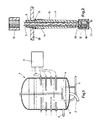
- FIG. 1 shows schematically a tank according to the invention which is more particularly suitable for the culture of microorganisms.
- the tank 1 is provided with an inlet 2 and an outlet 3 used to supply and discharge a liquid medium 4.
- the tank may also include a gas supply pipe 5.
- the tank 1 also comprises a gyratory element 6 to create turbulances in the medium 4. Openings 7 are provided in the wall of the tank 1, through which optical conductors 8 made of synthetic material extend. One end of these conductors 8 is connected to a light source 9 which sends light into the optical conductors. Another end of the optical conductors 8 is inside the vessel 1 and transmits light into the medium 4.
- Polymethylacrylate conductors having a diameter greater than 2 mm, advantageously between 7 and 15 mm, but preferably d '' about 10mm, particularly suitable. These polymethylacrylate optical conductors can, if necessary, be surrounded by a Teflon sheath having a thickness of approximately 1.5 mm.
- the optical conductor 8 does not come into direct contact with the liquid medium 4, since, as illustrated in FIG. 2, the conductor is inside an envelope 10 which is part of the tank.
- This envelope 10 may have different shapes but preferably has the shape of a tube.
- this envelope is formed by an element 11 in the form of a tube, one end of which is fixed to the external wall 20 of the tank 1 and the other end of which is closed off using a lens 12, by example a convex lens.
- the connection between the element 11 in the form of a tube and the wall of the tank 1 is sealed using an O-ring 13 which, during tightening, is wedged between a stop 14, applied to the wall of this element 11, and the internal wall of the tank.
- the optical conductor 8 is fixed to this envelope by means of a fixing ring 15, which can be screwed onto the end of the tube-shaped element 11, which projects from the opening in the wall .
- the end of the optical conductor 8 abuts against the lens 12.
- This lens forms an optical transmission member which transmits in the medium 4 the light exiting at the end of the conductor 8. Because the light beam is concentrated, this lens 12 forms, inside the middle 4, a light spot.
- this lens is detachably fixed to the element 11 in the form of a tube. In the example of Figure 2, this is achieved using a ring 16 which can be screwed onto the end of the tube-shaped element 11, which ring 16 is provided with a flange 17 which extends towards the inside of the tube.
- An O-ring 18 and a silicone seal 19 applied to the rim 17 ensure a good seal when the ring 16 is fixed to the end of the tube-shaped element 11.
- the optical transmission element need not necessarily be formed by a lens.
- Other elements capable of transmitting light such as a prism or a glass plate, can also be used.
- the optical transmission member can also be formed by a combination of these elements, for example by a glass plate with, between the latter and the end of the optical conductor, a lens.
- a tank according to the invention can be sterilized without compromising the light-conducting capacities of the optical conductors 8.
- the tank 1 can, for example, be sterilized for 20 minutes by injecting 120 ° steam into it. Since the casing 10 protects the optical conductors against the vapor, the latter therefore do not come into contact with this vapor. It has been found more particularly for conductors made of polymethylacrylate that, provided that they are protected against vapor, these do not lose their light conduction capacity after ten sterilizations at 120 °. Tests have revealed that they have retained 95% of their initial light conduction capacity. However, when they came into contact with the steam during sterilization, they became opaque.
- a tank according to the invention Another advantage of a tank according to the invention is that the optical transmission members form light spots in the medium.
- the light emitted by this organ in the medium penetrates relatively far into this medium, for example at a distance of approximately 10 cm. Thanks to this, a limited number of spots is sufficient, for example 1 spot per liter.
- a very short time of exposure to light is sufficient since a significantly longer time is necessary to transform the energy thus captured into biomass.
- the use of lenses makes it possible to concentrate the light in the medium or possibly to disperse this light when a high concentration of light is not necessary.
- envelopes whose internal dimensions correspond approximately to those of the optical conductors, these envelopes take up only a very limited space in the tank. There is therefore sufficient room for the liquid medium and agitation can therefore easily be carried out. We could possibly still save space by dividing the optical conductor and therefore also the envelope, so that from each envelope only one or two light spots are emitted.
- the envelopes 10 can also serve as counter-blades, they can consist for example of four vertical rows as illustrated in FIG. 1. If necessary, the four envelopes of the same row can be connected and form a vertical counter-blade .
- the envelopes can thus be formed from any material, such as for example metal or glass.
- the envelopes can be formed from a glass tube closed at one end.
Landscapes
- Life Sciences & Earth Sciences (AREA)
- Engineering & Computer Science (AREA)
- Health & Medical Sciences (AREA)
- Wood Science & Technology (AREA)
- Organic Chemistry (AREA)
- Chemical & Material Sciences (AREA)
- Bioinformatics & Cheminformatics (AREA)
- Zoology (AREA)
- Genetics & Genomics (AREA)
- Biotechnology (AREA)
- Sustainable Development (AREA)
- Microbiology (AREA)
- Biomedical Technology (AREA)
- Biochemistry (AREA)
- General Engineering & Computer Science (AREA)
- General Health & Medical Sciences (AREA)
- Molecular Biology (AREA)
- Apparatus Associated With Microorganisms And Enzymes (AREA)
Applications Claiming Priority (2)
| Application Number | Priority Date | Filing Date | Title |
|---|---|---|---|
| BE9000489A BE1004125A4 (fr) | 1990-05-08 | 1990-05-08 | Cuve pour des processus necessitant un apport de lumiere. |
| BE9000489 | 1990-05-08 |
Publications (1)
| Publication Number | Publication Date |
|---|---|
| EP0456630A1 true EP0456630A1 (de) | 1991-11-13 |
Family
ID=3884785
Family Applications (1)
| Application Number | Title | Priority Date | Filing Date |
|---|---|---|---|
| EP91870076A Withdrawn EP0456630A1 (de) | 1990-05-08 | 1991-05-08 | Gefäss für das Verfahren, das eine Lichtzufuhr erfordert |
Country Status (2)
| Country | Link |
|---|---|
| EP (1) | EP0456630A1 (de) |
| BE (1) | BE1004125A4 (de) |
Cited By (3)
| Publication number | Priority date | Publication date | Assignee | Title |
|---|---|---|---|---|
| DE102006033326A1 (de) * | 2006-07-19 | 2008-01-31 | Forschungszentrum für Medizintechnik und Biotechnologie e.V. | Kulturgefäß |
| DE102018108327A1 (de) * | 2018-04-09 | 2019-10-10 | Schott Ag | Photobioreaktor mit Vorrichtung zur Abgabe elektromagnetischer Strahlung, Vorrichtung zur Abgabe elektromagnetischer Strahlung sowie Verfahren zur Vermehrung oder Kultivierung biologischen Materials, Verfahren zum Präparieren von biologischem Material und/oder Herstellen von Pharmazeutika, insbesondere Biopharmazeutika |
| US11788669B2 (en) | 2018-04-09 | 2023-10-17 | Schott Ag | Device for supporting an image capturing device on a bioreactor, bioreactor with device for supporting an image capturing device, and method for propagation or cultivation of biological material |
Citations (3)
| Publication number | Priority date | Publication date | Assignee | Title |
|---|---|---|---|---|
| EP0084325A2 (de) * | 1982-01-16 | 1983-07-27 | Kei Mori | Photosynthesereaktor |
| DE8703478U1 (de) * | 1987-03-07 | 1987-06-25 | Pohl, Peter, Prof. Dr., 24242 Felde | Geschlossener Bioreaktor mit Innenbelichtung |
| US4952511A (en) * | 1987-06-11 | 1990-08-28 | Martek Corporation | Photobioreactor |
Family Cites Families (1)
| Publication number | Priority date | Publication date | Assignee | Title |
|---|---|---|---|---|
| JPS59111104A (ja) * | 1982-12-15 | 1984-06-27 | Mitsubishi Rayon Co Ltd | 光伝送繊維 |
-
1990
- 1990-05-08 BE BE9000489A patent/BE1004125A4/fr not_active IP Right Cessation
-
1991
- 1991-05-08 EP EP91870076A patent/EP0456630A1/de not_active Withdrawn
Patent Citations (3)
| Publication number | Priority date | Publication date | Assignee | Title |
|---|---|---|---|---|
| EP0084325A2 (de) * | 1982-01-16 | 1983-07-27 | Kei Mori | Photosynthesereaktor |
| DE8703478U1 (de) * | 1987-03-07 | 1987-06-25 | Pohl, Peter, Prof. Dr., 24242 Felde | Geschlossener Bioreaktor mit Innenbelichtung |
| US4952511A (en) * | 1987-06-11 | 1990-08-28 | Martek Corporation | Photobioreactor |
Non-Patent Citations (1)
| Title |
|---|
| PATENT ABSTRACTS OF JAPAN, Vol. 8, No. 233 (P-309)(1670) 26 Octobre 1974; & JP,A,59 111 104 (MITSUBISHI RAYON K.K.) 27 Juin 1984, le document en entier. * |
Cited By (4)
| Publication number | Priority date | Publication date | Assignee | Title |
|---|---|---|---|---|
| DE102006033326A1 (de) * | 2006-07-19 | 2008-01-31 | Forschungszentrum für Medizintechnik und Biotechnologie e.V. | Kulturgefäß |
| DE102006033326B4 (de) * | 2006-07-19 | 2012-03-22 | Holger Plettenberg | Kulturgefäß |
| DE102018108327A1 (de) * | 2018-04-09 | 2019-10-10 | Schott Ag | Photobioreaktor mit Vorrichtung zur Abgabe elektromagnetischer Strahlung, Vorrichtung zur Abgabe elektromagnetischer Strahlung sowie Verfahren zur Vermehrung oder Kultivierung biologischen Materials, Verfahren zum Präparieren von biologischem Material und/oder Herstellen von Pharmazeutika, insbesondere Biopharmazeutika |
| US11788669B2 (en) | 2018-04-09 | 2023-10-17 | Schott Ag | Device for supporting an image capturing device on a bioreactor, bioreactor with device for supporting an image capturing device, and method for propagation or cultivation of biological material |
Also Published As
| Publication number | Publication date |
|---|---|
| BE1004125A4 (fr) | 1992-09-29 |
Similar Documents
| Publication | Publication Date | Title |
|---|---|---|
| EP0733923B1 (de) | Beleuchtungsanordnung mit einem Bündel von optischen Fasern und Verfahren zur Erzeugung einer solchen Anordnung | |
| CA2648069C (fr) | Protection pour endoscope et endoscope correspondant | |
| US6104853A (en) | Detachable laser probe having reduced attenuation | |
| EP0571306A1 (de) | Vorrichtung und Verfahren zur Entfernung von Ablagerungen auf Wänden von Körpergefässen | |
| FR2605230A1 (fr) | Dispositif d'irradiation lumineuse pour administrer un traitement medical oral a des gencives malades | |
| EP0259414A1 (de) | Vorrichtung zur thermischen behandlung dünner körper wie siliziumdioxid-wafer. | |
| BE1004125A4 (fr) | Cuve pour des processus necessitant un apport de lumiere. | |
| FR2644225A1 (fr) | Dispositif de rayonnement de lumiere | |
| CA2075821C (fr) | Sonde multicanalaire a au moins trois canaux longitudinaux independants utilisable pour la destruction d'obstacles lithiasiques par voie endoscopique ainsi que pour la destructionde depots mineraux dans des conduits | |
| FR2974580A1 (fr) | Recipient pour la culture in vitro de materiel vegetal en conditions steriles, par immersion temporaire | |
| FR2567277A1 (fr) | Procede de decontamination et de nettoyage de protheses oculaires, en particulier de lentilles de contact, et dispositif pour la mise en oeuvre de ce procede | |
| EP2328624B1 (de) | Dekontaminationsvorrichtung mit einer lichtquelle für objekte mit vertiefungen | |
| EP2643448B1 (de) | Solar-photobioreaktor mit kontrollierter volumenstromverdünnung | |
| FR2651508A1 (fr) | Dispositif de traitement de pieces par chocs laser. | |
| EP0079827A1 (de) | Vorrichtung zur Sterilisation von kleinen medizinischen oder paramedizinischen Instrumenten | |
| FR2517172A1 (fr) | Ecran thermique | |
| FR2641446A1 (fr) | Radiateur de lumiere pour l'elevage des poissons | |
| EP0022389A1 (de) | Verfahren und Anlage zum Klimatisieren von Gewächshäusern und Schutzglocken | |
| FR2790110A1 (fr) | Connecteur optique perfectionne, destine en particulier a operer dans un environnement de haute pression | |
| FR2694628A1 (fr) | Cellule photo-électrique, notamment submersible, et attache rapide pour sa fixation sur une source de lumière ultraviolette. | |
| WO1995010732A1 (fr) | Generateur de lumiere a bouclier thermique pour ensemble d'eclairage ou d'illumination mettant en oeuvre un guide de lumiere | |
| EP3823446B1 (de) | Vorrichtung zur aufnahme von hornhautgewebe zur photonenbehandlung davon | |
| FR2649802A1 (fr) | Connecteur pour un guide d'ondes lumineuses a fibres optiques | |
| FR3058778A1 (fr) | Dispositif d'eclairage sous eau pour l'inspection visuelle d'un equipement de reacteur nucleaire et procede associe | |
| FR2931144A3 (fr) | Unite d'irradiation par immersion, module a rayonnement ultraviolet comprenant une telle unite et systeme de montage avec plaque de base pour une telle unite |
Legal Events
| Date | Code | Title | Description |
|---|---|---|---|
| PUAI | Public reference made under article 153(3) epc to a published international application that has entered the european phase |
Free format text: ORIGINAL CODE: 0009012 |
|
| AK | Designated contracting states |
Kind code of ref document: A1 Designated state(s): BE DE FR IT LU NL |
|
| 17P | Request for examination filed |
Effective date: 19920311 |
|
| 17Q | First examination report despatched |
Effective date: 19940506 |
|
| STAA | Information on the status of an ep patent application or granted ep patent |
Free format text: STATUS: THE APPLICATION IS DEEMED TO BE WITHDRAWN |
|
| 18D | Application deemed to be withdrawn |
Effective date: 19940917 |