EP0456714B1 - Anordnung für ein befestigungselement - Google Patents
Anordnung für ein befestigungselement Download PDFInfo
- Publication number
- EP0456714B1 EP0456714B1 EP90902855A EP90902855A EP0456714B1 EP 0456714 B1 EP0456714 B1 EP 0456714B1 EP 90902855 A EP90902855 A EP 90902855A EP 90902855 A EP90902855 A EP 90902855A EP 0456714 B1 EP0456714 B1 EP 0456714B1
- Authority
- EP
- European Patent Office
- Prior art keywords
- mounting bracket
- connecting device
- intended
- attachment
- accordance
- Prior art date
- Legal status (The legal status is an assumption and is not a legal conclusion. Google has not performed a legal analysis and makes no representation as to the accuracy of the status listed.)
- Expired - Lifetime
Links
Images


Classifications
-
- B—PERFORMING OPERATIONS; TRANSPORTING
- B25—HAND TOOLS; PORTABLE POWER-DRIVEN TOOLS; MANIPULATORS
- B25B—TOOLS OR BENCH DEVICES NOT OTHERWISE PROVIDED FOR, FOR FASTENING, CONNECTING, DISENGAGING, OR HOLDING
- B25B31/00—Hand tools for applying fasteners
-
- E—FIXED CONSTRUCTIONS
- E04—BUILDING
- E04F—FINISHING WORK ON BUILDINGS, e.g. STAIRS, FLOORS
- E04F13/00—Coverings or linings, e.g. for walls or ceilings
- E04F13/02—Coverings or linings, e.g. for walls or ceilings of plastic materials hardening after applying, e.g. plaster
- E04F13/04—Bases for plaster
- E04F13/045—Means for fastening plaster-bases to a supporting structure
-
- E—FIXED CONSTRUCTIONS
- E04—BUILDING
- E04F—FINISHING WORK ON BUILDINGS, e.g. STAIRS, FLOORS
- E04F13/00—Coverings or linings, e.g. for walls or ceilings
- E04F13/07—Coverings or linings, e.g. for walls or ceilings composed of covering or lining elements; Sub-structures therefor; Fastening means therefor
- E04F13/08—Coverings or linings, e.g. for walls or ceilings composed of covering or lining elements; Sub-structures therefor; Fastening means therefor composed of a plurality of similar covering or lining elements
- E04F13/0801—Separate fastening elements
- E04F13/0832—Separate fastening elements without load-supporting elongated furring elements between wall and covering elements
- E04F13/0833—Separate fastening elements without load-supporting elongated furring elements between wall and covering elements not adjustable
- E04F13/0835—Separate fastening elements without load-supporting elongated furring elements between wall and covering elements not adjustable the fastening elements extending into the back side of the covering elements
- E04F13/0837—Separate fastening elements without load-supporting elongated furring elements between wall and covering elements not adjustable the fastening elements extending into the back side of the covering elements extending completely through the covering elements
-
- E—FIXED CONSTRUCTIONS
- E04—BUILDING
- E04B—GENERAL BUILDING CONSTRUCTIONS; WALLS, e.g. PARTITIONS; ROOFS; FLOORS; CEILINGS; INSULATION OR OTHER PROTECTION OF BUILDINGS
- E04B1/00—Constructions in general; Structures which are not restricted either to walls, e.g. partitions, or floors or ceilings or roofs
- E04B1/62—Insulation or other protection; Elements or use of specified material therefor
- E04B1/74—Heat, sound or noise insulation, absorption, or reflection; Other building methods affording favourable thermal or acoustical conditions, e.g. accumulating of heat within walls
- E04B1/76—Heat, sound or noise insulation, absorption, or reflection; Other building methods affording favourable thermal or acoustical conditions, e.g. accumulating of heat within walls specifically with respect to heat only
- E04B1/762—Exterior insulation of exterior walls
- E04B1/7629—Details of the mechanical connection of the insulation to the wall
Definitions
- the present invention relates to an anchoring device for anchoring a building layer to an attachment surface of a substrate such as a wall, which device comprises a mounting bracket for attachment to the substrate, a connecting device extending outwardly from the mounting bracket and for extending through the building layer, a fastening device attached to the opposite end of the connecting device and a fastening element co-operating with the fastening device for securing the building layer to the attachment surface via the connecting element.
- SE-B-403 310 SE-B-423 419 is an arrangement of the above indicated kind, which has the ability to alternate mechanically between a free and a locked position in order, when in the locked position, to permit a layer of thermal insulation to be inserted over the element, and in addition to support a surface layer, such as reinforced rendering.
- the function is to take up movements due, for example, to varying climatic stresses.
- the SE, B, 451.478 discloses an anchoring device for anchoring a building layer to an attachment surface of a substrate.
- Said device comprises a mounting bracket for attachment to the substrate, a connecting device extending from the mounting bracket and for extending through the building layer, a fastening device attached to the opposite end of the connecting device.
- a fastening element is co-operating with the fastening device for securing the building layer to the attachment surface via the connecting element.
- the connecting device at said known anchoring device consists of two rods made of metal and which are parallell to each other extending at right angles to the wall.
- the known device does not consist of a flexible wire made of metallic material and which exhibits flexibility and which extends at an initial angle in a downward direction from the intended mounting bracket for the fastening, so that angular deformation is achieved forcibly in the flexible wire.
- the idea with said flexible metallic wire is that it results in a smaller flexural rigidity in the total construction, yet retaining the tensile strength, and that the outer end of the wire describes a downward movement along the circumference of a circle and moves inwards towards the attachment plane at the same time.
- the SE, B, 455.951 also discloses an anchoring device similar to the device discussed above.
- a rod made of metallic material is rigidly connected to an attachment. When the force is too high, the connection will break and the rod will swing downwards from a right angle from a wall to which it is fastened. The drawback with this device has already been discussed above.
- the principal object of the present invention is thus, in the first place, to make available an arrangement which, inter alia, solves said problem simply and effectively.
- the connecting device is in the form of a flexible cable made of metallic material which extends downwardly from the mounting bracket at an initial inclination angle relative to the normal extending from the vertical plane of the mounting bracket, so that angular deformation is achieved forcibly in the flexible cable.
- An arrangement 1; 101; 201; 301; 401 for a fastening element arranged in accordance with the present invention which is intended to be used in conjunction with the anchoring of a building layer 2, 21, 3 along an intended attachment surface, principally for the purpose of enabling thermal insulation 2-21 and/or surface layers, such as rendering 3, to be applied to the outside 4A of a wall 4 or some other upright substratum, comprises a mounting bracket 5, 51; 105, 1051; 205, 2051; 305; 405 so arranged as to be secured to the intended substratum 4, a preferably stiff yet still flexible connecting device 6; 106; 206; 306; 406 extending outwards from said mounting bracket 5, 51; 105, 1051; 205, 2051; 305; 405, and a number of fastening devices 7, 71; 107; 207, 2071; 307; 407; 1000, so arranged as to be capable of holding the building layer 2; 21; 3 in question securely in place via the connecting device 6; 106;
- the connecting device 6; 106; 206; 306; 406 consists in accordance with the invention of a wire-shaped flexible part, a flexible line, for example a cable made of a plastic and/or metallic material having an appropriate number of threads, etc., which is so arranged through the influence of a mounting bracket 5A; 105A; 1051A; 205A; 2051A; 305A; 405A as to bring about the forcible angular deformation of said device 6; 106; 206; 306; 406 from the area of said associated mounting bracket 5; 51; 105; 1051; 205; 2051; 305; 405.
- Said angular deformation is achieved forcibly relative to an imaginary normal which extends from the intended mounting bracket and from the wall surface 4A, so that the point of attachment to the mounting bracket is situated on a plane above the plane for the fastening device for the arrangement when the arrangement is attached to the intended attachment surface 4A, for example on a wall 4.
- the effect of the arrangement of the connecting device with such angular deflection is intended to be utilized in such a way that the fastening device 7; 107; 207; 2071; 307; 407 is positioned below the point of attachment on the intended upright wall 4, etc., i.e. extends downwards and outwards from the intended fastening point 9 for the fastening arrangement 1.
- the first effect of the arrangement is then that the underside of the connecting device interacts with the insulation 2, 21, so that same is forced in towards and is held securely in position against the wall 4 or some other suitable attachment surface before a special locking means 1000 is put in position in the fastening device 7; 107; 2071; 307; 407.
- the second effect of said arrangement 1; 101; 201; 301; 401 takes place when its outer end is subjected to load, when the latter describes a downward movement along the circumference of a circle, which means that it will move inwards towards the attachment plane at the same time.
- the initial angle is so adapted in the construction of current interest that the inward movement is "arrested" by the substratum as quickly as possible in order to prevent the downward movement from assuming excessively large proportions.
- the relationship between the downward movement and the inward movement in the quadrant concerned is such that the rate of increase in the downward movement reduces at the same time as the rate of increase in the inward movement increases.
- the inward movement generates a normal force acting against the thermal insulation 2; 21 and in so doing contributes considerably to retaining the system in place because of the frictional force which arises.
- the connecting device 6; 106; 206; 306; 406 is thus held securely at the centre of the attachment point 10, which means that any moment will be absorbed fully in said device.
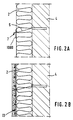
- the connecting device 6 is attached by one end 6A to one part 12; 121 of a sleeve-shaped mounting bracket, which may be constituted by an attachment block 12; 121 made of a metal material connected to the inner end of, for example, a slotted and preferably expandable attachment sleeve, and which, when a load is applied to the connecting device 6, is forced against the mounting bracket 5, to which tractive forces acting upon the connecting device 6 are transferred as compressive forces, and extends internally within the attachment sleeve 5; 51, with the part of the connecting device 6 which extends from the attachment sleeve 5; 51 being enclosed by a guide sleeve 5A projecting from the attachment sleeve 5 at the intended initial angle X.
- a wedge-shaped combined driving and clamping element 50 which can be accommodated in the internal space 51 of the attachment sleeve, can then be included in the arrangement 1 in order, inter alia, to permit the driving of the mounting bracket 5 into the hole 10 and to clamp the mounting bracket 5 securely in the intended attachment hole 10 at the intended fastening point 9, especially when the invention is applied for the so-called push-through assembly of intended insulation, etc., in order to be able to gain access to holes 57 extending through the insulations, etc., 21, but also in order to clamp the device 6 securely to the intended mounting bracket after the driving in of same.
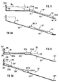
- the arrangement 101 thus arranged consists of a mounting bracket 105 made of a rigid material, which in one case extends perpendicularly outwards from the intended wall attachment part 105B, in which are present attachment holes 193 to accept mounting bolts, etc., 194 for securing the arrangement to the intended wall, etc., 4.
- a flexible cable 106 extends at the intended angle CX downwards from the central axis 108 of said hole through the angular deflection of an angled mounting bracket 105A attached to the mounting bracket 105, which angled mounting bracket can consist of a tongue, etc., enclosing the cable.
- a fastening device 107 which can similarly consist of a tongue which encloses the free end 106B of the cable, can exhibit attachment holes 96, 97 to accommodate an appropriate locking means 1000.
- FIG. 8A Illustrated in Fig. 8A is an example of how the downward deflection is produced by a mounting bracket 1051 being angled downwards in order to achieve the effect referred to above, in conjunction with which the mounting bracket 1051A extends essentially in line with the main part of said mounting bracket 1051.
- FIG. 9-9A A third example of an attachment arrangement 201 in accordance with the invention is illustrated in Figs. 9-9A, in which a mounting bracket 205 and 2051, which is angled at right-angles, or at the intended initial angle CCX1 from the foot part 290 of the intended mounting part of the intended mounting bracket 205, and from the central axis of the central axis 208 passing through the hole 293 of the foot part, in conjunction with which an extension part 275, 2751 projecting from the outer end 206B, 206B1 of the connecting device and connected to it by means of a mounting bracket 205A, 2051A, is angled downwards at the intended initial angle CCX; CCX1 in Fig. 9, or extends essentially straight in line with the downward-angled cable 2061, Fig. 9A.
- Said extension parts preferably consist of curved strips of sheet metal or similar elements.
- the connecting device 306 is attached to a mounting stem 377 capable of being introduced into the internal space 376 inside an attachment sleeve 375, from the outer end 377A of which the connecting device 306 is caused to extend downwards at the intended initial angle CCCX by the influence of a guide sleeve 312, in conjunction with which the mounting stem 377 and preferably also the attachment sleeve 375 can be driven into an intended attachment hole by means of a driving-in tool 150 actuated by impact or by some other imparted movement and capable of interacting with a stop component 379, 380, which is preferably situated at their 375, 377 respective outer ends 375A, 377A.
- the assembly tool 150 which is shown in Fig. 12, can consist of a striking part 178 which is capable of being introduced into a space 181 in an assembly sleeve 182 capable of being introduced through a hole, etc., 57 through the insulation 21, which assembly sleeve is a part of the tool 150, in order to facilitate the assembly of a fastening element arrangement 1; 301; 401.
- a fastening element arrangement 401 which is illustrated in the drawings in Fig. 11, its associated connecting device 406 is attached at one end 406A of the device to a mounting bracket 405A exhibiting the intended initial angle CCCCX, which mounting bracket preferably consists of a sleeve or clamp, etc., exhibiting a foot component 490, which is so arranged as to enclose and, preferably by clamping, as to retain one end 406A of the connecting device.
- the connecting device 406 can in this case exhibit a mounting bracket 405 comprising a hole 493 to accommodate a fastening element 194, in conjunction with which the mounting bracket 405 exhibits an abutment part 495 interacting with the head 195 of the fastening element or a washer, etc., 499.
- a sleeve-shaped assembly tool 281 is also intended to be capable of being applied in conjunction with the fastening of such an arrangement 101; 201; 401 by "push-through assembly", and with the help of a driving-in tool 278 for the element which is a part of the tool 281 and is capable of being introduced into an assembly sleeve 282, the arrangement can be driven securely into place at the intended fastening point.
- the arrangement shall function in such a way that, on the one hand, it shall be capable of being securely attached to, for example, a facade with the subsequent assembly/installation of, for example, thermal insulation 2 plus reinforcement mesh 13, and yet shall still exhibit sufficient flexural rigidity with retained flexibility, and, on the other hand, its function shall be such that the thermal insulation shall be installed first, holes drilled through the insulation and into, for example, any underlying wall 4, whereupon the arrangement shall be capable, with the help of special tools, of being introduced through the insulation 2 and into the attachment hole 10.
- PUSH-ON ASSEMBLY an example of which is shown in Figs. 1-2
- PUSH-THROUGH ASSEMBLY an example of which is shown in Figs. 3-4.
- the use of a special tool may be necessary, especially if quite large thicknesses of insulation are to be penetrated.
- Such tools 150 and 281 are shown respectively in Figs. 12 and 13.
- the method of "clothing" the cable with a close-fitting rigid tube is used in order to bring about angular deformation of the cable at the point where it leaves the attachment hole.
- the tube which is under tension at the same time as the cable, is bent in this way to the desired angle.
- the connecting device 7; 71; 107; 207; 2071; 307; 407 appropriately exhibits at least two accommodating openings 96, 97 distributed along the longitudinal extent of said device, which openings are situated at a certain distance from an associated mounting bracket which is a part of the arrangement, and are capable of interacting with a locking means 1000.
- the locking means may consist of a curved spring locking means, as shown in Fig. 5, the inserted end 1000A of which is slightly curved to enable it to be inserted more easily into the lock holes, and with a widened stop part 1000B, formed by flattening, for example, being so arranged as to prevent the locking means from falling through the intended hole 96, 97.
- the outer part of the pendulum part and the spring locking means 1000 are so adapted to one another that the spring locking means will snap into engagement with the substratum. This effect means that the locking means will not interfere with the rendering work, for example.
- the spring locking means is constructed in such a way that it will make uniform contact with the substratum around the "locking point".
- FIG. 6 Shown in Fig. 6 is the manner in which notches 98; 99 in the connecting device 7 can be so arranged as to interact with intended locking devices 1000, so that these are held securely transversely, and as to facilitate, inter alia, rendering work, etc.
- An inner hole 96 is intended, via an inserted locking means 1000, to hold a layer 2, 21 of thermal insulation, for example, in position until the following operation, i.e. the application of reinforcing mesh 13 before, for example, rendering is carried out, when a locking arrangement is also introduced into the outermost hole 97 in order to hold the reinforcing mesh 13, for example, in position.
Landscapes
- Engineering & Computer Science (AREA)
- Architecture (AREA)
- Civil Engineering (AREA)
- Structural Engineering (AREA)
- Mechanical Engineering (AREA)
- Installation Of Indoor Wiring (AREA)
- Dowels (AREA)
- Building Environments (AREA)
- Surgical Instruments (AREA)
- Seal Device For Vehicle (AREA)
- Electrical Discharge Machining, Electrochemical Machining, And Combined Machining (AREA)
- Paper (AREA)
- Piezo-Electric Or Mechanical Vibrators, Or Delay Or Filter Circuits (AREA)
- Joining Of Building Structures In Genera (AREA)
- Connection Of Plates (AREA)
- Finishing Walls (AREA)
- Portable Nailing Machines And Staplers (AREA)
- Finger-Pressure Massage (AREA)
- Clamps And Clips (AREA)
Claims (9)
- Verankerungsvorrichtung zum Verankern einer Baustoffschicht (2, 2¹, 3, 13) an einer Befestigungsoberfläche (4A) eines Befestigungsgrundes (4), etwa einer Wand, mit einem Anbindungselement (5, 5¹; 105, 105¹; 205, 205¹; 305; 405) zur Befestigung an dem Befestigungsgrund, mit einem Verbindungselement (6; 106; 206; 306; 406), das sich von dem Anbindungselement wegweisend durch die Baustoffschicht erstreckt, mit einer am gegenüberliegenden Ende des Verbindungselements angeordneten Spannvorrichtung (7, 7¹; 107; 207, 207¹, 307; 407) und mit einem Befestigungselement (1000), das über das Verbindungselement mit der Spannvorrichtung zum Befestigen der Baustoffschicht an der Befestigungsoberfläche zusammenwirkt, dadurch gekennzeichnet, daß das Verbindungselement ein flexibles Seil (6; 106; 206; 306; 406) aus einem metallischen Werkstoff ist, das sich in einem Ausgangsneigungswinkel (X; CX; CCX, CCX¹; CCCX; CCCCX) bezüglich der von der vertikalen Ebene des Anbindungselementes ausgehenden Normalen von dem Anbindungselement nach unten weisend erstreckt, so daß sich zwangsläufig eine Abwinklung des flexiblen Seiles einstellt.
- Verankerungsvorrichtung nach Anspruch 1, dadurch gekennzeichnet, daß das Verbindungselement (6; 106; 206; 306; 406) an einem Ende (6A) an einem Element (12) eines hülsenförmigen Anbindungselementes (5) angebracht ist und sich innen durch die vorgesehene geschlitzte und dehnbare Befestigungshülse (5) erstreckt (Fig. 7 bis Fig. 7C).
- Verankerungsvorrichtung nach Anspruch 2, dadurch gekennzeichnet, daß der Abschnitt des Verbindungselements (6), der in einer Führungshülse (5A) von der Befestigungshülse (5) wegweisend angeordnet ist, von der Befestigungshülse (5) in dem vorgesehenen Ausgangswinkel (X) wegweist.
- Verankerungsvorrichtung nach einem der Ansprüche 2 oder 3, dadurch gekennzeichnet, daß ein keilförmiges kombiniertes Eintreib- und Klemmelement (50) in den Innenraum (51) einsetzbar ist, um unter anderem das Eintreiben des Anbindungselementes und das sichere Verklemmen des Anbindungselementes in dem vorgesehenen Befestigungsloch (10) im vorgesehenen Befestigungspunkt (9) zu erlauben.
- Verankerungsvorrichtung nach Anspruch 1, dadurch gekennzeichnet, daß das Verbindungselement (306) an einem Befestigungsstopfen (377) angebracht ist, der von dem äußeren Ende (377A), von dem das Verbindungselement (306) in dem vorgesehenen Ausgangswinkel (CCCX) durch eine Führungshülse (312) (Fig. 10) nach unten gedrückt wird, in den Innenraum (376) einer Befestigungshülse (375) einführbar ist, und daß der Befestigungsstopfen (377) und vorzugsweise auch die Befestigungshülse (375) ein mit dem Eintreibwerkzeug (150) zusammenwirkendes Anschlagelement (379, 380) aufweisen, wobei das Anschlagelement vorzugsweise an den jeweiligen äußeren Enden (375A, 377A) angeordnet ist.
- Verankerungsvorrichtung nach Anspruch 1, dadurch gekennzeichnet, daß das Verbindungselement (406) an einem Ende (406A) an einem Anbindungselement (405) befestigt ist, das den vorgesehenen Ausgangswinkel (CCCCX) aufweist und das vorzugsweise aus einer einen Fußbereich (490) aufweisenden Hülse oder einer Klemme oder dergleichen besteht, die so angeordnet ist, daß ein Ende (406A) des Verbindungselements umschlossen und sicher verklemmt ist (Fig. 11).
- Verankerungsvorrichtung nach Anspruch 6, dadurch gekennzeichnet, daß das Verbindungselement (406) ein Anbindungselement (405) mit einem Loch (493) zur Aufnahme eines Befestigungselementes (194) aufweist, das zusammenwirkend mit dem Anbindungselement (405) als Widerlager (495) ausgebildet ist und das mit dem Kopf oder dergleichen eines Befestigungselements zusammenwirkt.
- Verankerungsvorrichtung nach einem der vorstehenden Ansprüche, dadurch gekennzeichnet, daß das Verbindungselement (7) wenigstens zwei Aufnahmeöffnungen (96, 97) aufweist, die in axialer Verlängerung des Elements vorgesehen sind, wobei die Öffnungen in einem gewissen Abstand von einem entsprechenden Anbindungselement angeordnet sind und wobei diese zur Aufnahme von Sicherungsmitteln (1000) geeignet sind.
- Verankerungsvorrichtung nach einem vorstehenden Ansprüche, dadurch gekennzeichnet, daß der Ausgangsneigungswinkel (X; CX; CCX, CCX¹; CCCX; CCCCX) zwischen 15 und 20 Grad ist.
Applications Claiming Priority (3)
| Application Number | Priority Date | Filing Date | Title |
|---|---|---|---|
| SE8900349A SE468995B (sv) | 1989-02-01 | 1989-02-01 | Anordning vid faestelement |
| SE8900349 | 1989-02-01 | ||
| PCT/SE1990/000047 WO1990008863A1 (en) | 1989-02-01 | 1990-01-22 | Arrangement for a fastening element |
Publications (2)
| Publication Number | Publication Date |
|---|---|
| EP0456714A1 EP0456714A1 (de) | 1991-11-21 |
| EP0456714B1 true EP0456714B1 (de) | 1994-05-18 |
Family
ID=20374915
Family Applications (1)
| Application Number | Title | Priority Date | Filing Date |
|---|---|---|---|
| EP90902855A Expired - Lifetime EP0456714B1 (de) | 1989-02-01 | 1990-01-22 | Anordnung für ein befestigungselement |
Country Status (9)
| Country | Link |
|---|---|
| EP (1) | EP0456714B1 (de) |
| AT (1) | ATE105897T1 (de) |
| AU (1) | AU5036890A (de) |
| DE (1) | DE69009043T2 (de) |
| DK (1) | DK0456714T3 (de) |
| FI (1) | FI94886C (de) |
| NO (1) | NO176889C (de) |
| SE (1) | SE468995B (de) |
| WO (1) | WO1990008863A1 (de) |
Families Citing this family (2)
| Publication number | Priority date | Publication date | Assignee | Title |
|---|---|---|---|---|
| AT402521B (de) * | 1994-05-17 | 1997-06-25 | Krassnitzer Theobald Ing | Wärme- und schallisolierung für mauerwerk |
| EP3786378A1 (de) * | 2019-08-29 | 2021-03-03 | Hilti Aktiengesellschaft | Befestigungsvorrichtung |
Family Cites Families (8)
| Publication number | Priority date | Publication date | Assignee | Title |
|---|---|---|---|---|
| SE316887B (de) * | 1966-08-18 | 1969-11-03 | Siporex Int Ab | |
| SE361184B (de) * | 1972-03-10 | 1973-10-22 | Svenska Flaektfabriken Ab | |
| SE398764C (sv) * | 1977-03-02 | 1979-08-20 | Essve Produkterab | Sett att vermeisolera husfasader samt anordning for genomforande av settet |
| SE429053B (sv) * | 1980-02-22 | 1983-08-08 | Straengbetong Ab | Sandwichelement av betong |
| FI62166C (fi) * | 1981-03-27 | 1982-11-10 | Sormat Oy | Anordning foer elastiskt faestande av isoleringar eller motsvarande material vid underlag |
| SE446999B (sv) * | 1984-03-27 | 1986-10-20 | Sabema Material Ab | Anordning for uppberning av isolering och fasadputs |
| SE451478B (sv) * | 1984-12-17 | 1987-10-12 | Thorsman & Co Ab | Festanordning for putsunderlag |
| SE455951C (sv) * | 1985-09-09 | 1989-11-27 | Strabruken Ab | Ledat faestelement foer att fasthaalla ett vaermeisoleringsskikt mot en vaegg |
-
1989
- 1989-02-01 SE SE8900349A patent/SE468995B/sv not_active IP Right Cessation
-
1990
- 1990-01-22 DE DE69009043T patent/DE69009043T2/de not_active Expired - Fee Related
- 1990-01-22 AU AU50368/90A patent/AU5036890A/en not_active Abandoned
- 1990-01-22 EP EP90902855A patent/EP0456714B1/de not_active Expired - Lifetime
- 1990-01-22 AT AT90902855T patent/ATE105897T1/de active
- 1990-01-22 WO PCT/SE1990/000047 patent/WO1990008863A1/en not_active Ceased
- 1990-01-22 DK DK90902855.7T patent/DK0456714T3/da active
-
1991
- 1991-07-30 FI FI913621A patent/FI94886C/fi not_active IP Right Cessation
- 1991-07-31 NO NO912983A patent/NO176889C/no unknown
Also Published As
| Publication number | Publication date |
|---|---|
| DK0456714T3 (da) | 1994-10-10 |
| FI94886B (fi) | 1995-07-31 |
| FI913621A0 (fi) | 1991-07-30 |
| NO912983D0 (no) | 1991-07-31 |
| ATE105897T1 (de) | 1994-06-15 |
| DE69009043T2 (de) | 1994-09-01 |
| DE69009043D1 (de) | 1994-06-23 |
| NO912983L (no) | 1991-07-31 |
| WO1990008863A1 (en) | 1990-08-09 |
| FI94886C (fi) | 1995-11-10 |
| NO176889C (no) | 1995-06-14 |
| NO176889B (no) | 1995-03-06 |
| EP0456714A1 (de) | 1991-11-21 |
| SE468995B (sv) | 1993-04-26 |
| AU5036890A (en) | 1990-08-24 |
| SE8900349D0 (sv) | 1989-02-01 |
Similar Documents
| Publication | Publication Date | Title |
|---|---|---|
| WO2007124533A1 (en) | Barrier improvements | |
| US5788403A (en) | Fire protection of steelwork | |
| EP0456714B1 (de) | Anordnung für ein befestigungselement | |
| US10232201B2 (en) | Fall arrest apparatus | |
| US11965342B2 (en) | Wire mounting solutions | |
| US5772169A (en) | Compression strut system for acoustic ceiling | |
| US5188690A (en) | Method for applying a covering on a substrate, a device for carrying out the method and a covering obtained by means of said method | |
| US4926607A (en) | Compression leg | |
| JP2004076433A (ja) | システム天井の吊り構造 | |
| CA2466283C (en) | Rock bolt | |
| JPH10238134A (ja) | 炭素繊維シートの端部固定方法 | |
| KR200258040Y1 (ko) | 이중 밴드케이블을 갖는 와이어 하네스 고정클립 | |
| US12416158B2 (en) | Support structures for insulation and other materials | |
| CN221202055U (zh) | 一种可调角度的管线卡排 | |
| JP6117961B1 (ja) | 勾配屋根における吊り天井下地構造及び既存吊り天井の下地改修方法 | |
| AU2002351425A1 (en) | Rock bolt | |
| JPH10210635A (ja) | 長尺可とう導波管の支持構造 | |
| JPH0141204Y2 (de) | ||
| JPH047228Y2 (de) | ||
| JP2598944Y2 (ja) | 安全索支持用支柱 | |
| JP2009275418A (ja) | 縦壁パネルの取付け構造およびベース金具 | |
| KR100413862B1 (ko) | 내진 보강 기구 | |
| JP4370052B2 (ja) | 火打ち金具 | |
| JPS63208301A (ja) | アンテナの取付金具 | |
| NZ280584A (en) | Brick or block veneer wall tie to be fixed to a support frame has a ductile portion therebetween |
Legal Events
| Date | Code | Title | Description |
|---|---|---|---|
| PUAI | Public reference made under article 153(3) epc to a published international application that has entered the european phase |
Free format text: ORIGINAL CODE: 0009012 |
|
| 17P | Request for examination filed |
Effective date: 19910724 |
|
| AK | Designated contracting states |
Kind code of ref document: A1 Designated state(s): AT BE CH DE DK ES FR GB IT LI LU NL SE |
|
| 17Q | First examination report despatched |
Effective date: 19920727 |
|
| GRAA | (expected) grant |
Free format text: ORIGINAL CODE: 0009210 |
|
| AK | Designated contracting states |
Kind code of ref document: B1 Designated state(s): AT BE CH DE DK ES FR GB IT LI LU NL SE |
|
| PG25 | Lapsed in a contracting state [announced via postgrant information from national office to epo] |
Ref country code: IT Free format text: LAPSE BECAUSE OF FAILURE TO SUBMIT A TRANSLATION OF THE DESCRIPTION OR TO PAY THE FEE WITHIN THE PRESCRIBED TIME-LIMIT;WARNING: LAPSES OF ITALIAN PATENTS WITH EFFECTIVE DATE BEFORE 2007 MAY HAVE OCCURRED AT ANY TIME BEFORE 2007. THE CORRECT EFFECTIVE DATE MAY BE DIFFERENT FROM THE ONE RECORDED. Effective date: 19940518 Ref country code: AT Effective date: 19940518 Ref country code: ES Free format text: THE PATENT HAS BEEN ANNULLED BY A DECISION OF A NATIONAL AUTHORITY Effective date: 19940518 Ref country code: BE Effective date: 19940518 Ref country code: SE Free format text: THE PATENT HAS BEEN ANNULLED BY A DECISION OF A NATIONAL AUTHORITY Effective date: 19940518 Ref country code: FR Effective date: 19940518 Ref country code: LI Effective date: 19940518 Ref country code: CH Effective date: 19940518 Ref country code: NL Effective date: 19940518 |
|
| REF | Corresponds to: |
Ref document number: 105897 Country of ref document: AT Date of ref document: 19940615 Kind code of ref document: T |
|
| REF | Corresponds to: |
Ref document number: 69009043 Country of ref document: DE Date of ref document: 19940623 |
|
| REG | Reference to a national code |
Ref country code: CH Ref legal event code: PL |
|
| REG | Reference to a national code |
Ref country code: DK Ref legal event code: T3 |
|
| EN | Fr: translation not filed | ||
| NLV1 | Nl: lapsed or annulled due to failure to fulfill the requirements of art. 29p and 29m of the patents act | ||
| PG25 | Lapsed in a contracting state [announced via postgrant information from national office to epo] |
Ref country code: LU Free format text: LAPSE BECAUSE OF NON-PAYMENT OF DUE FEES Effective date: 19950131 |
|
| PLBE | No opposition filed within time limit |
Free format text: ORIGINAL CODE: 0009261 |
|
| STAA | Information on the status of an ep patent application or granted ep patent |
Free format text: STATUS: NO OPPOSITION FILED WITHIN TIME LIMIT |
|
| 26N | No opposition filed | ||
| REG | Reference to a national code |
Ref country code: GB Ref legal event code: 732E |
|
| PGFP | Annual fee paid to national office [announced via postgrant information from national office to epo] |
Ref country code: GB Payment date: 20000121 Year of fee payment: 11 |
|
| PGFP | Annual fee paid to national office [announced via postgrant information from national office to epo] |
Ref country code: DK Payment date: 20000125 Year of fee payment: 11 |
|
| PGFP | Annual fee paid to national office [announced via postgrant information from national office to epo] |
Ref country code: DE Payment date: 20000223 Year of fee payment: 11 |
|
| PG25 | Lapsed in a contracting state [announced via postgrant information from national office to epo] |
Ref country code: GB Free format text: LAPSE BECAUSE OF NON-PAYMENT OF DUE FEES Effective date: 20010122 Ref country code: DK Free format text: LAPSE BECAUSE OF NON-PAYMENT OF DUE FEES Effective date: 20010122 |
|
| GBPC | Gb: european patent ceased through non-payment of renewal fee |
Effective date: 20010122 |
|
| REG | Reference to a national code |
Ref country code: DK Ref legal event code: EBP |
|
| PG25 | Lapsed in a contracting state [announced via postgrant information from national office to epo] |
Ref country code: DE Free format text: LAPSE BECAUSE OF NON-PAYMENT OF DUE FEES Effective date: 20011101 |