EP0456829A1 - Dispositif de traitement thermique et procede de sechage de pellicules minces fonctionnelles utilisant ledit dispositif - Google Patents
Dispositif de traitement thermique et procede de sechage de pellicules minces fonctionnelles utilisant ledit dispositif Download PDFInfo
- Publication number
- EP0456829A1 EP0456829A1 EP90917342A EP90917342A EP0456829A1 EP 0456829 A1 EP0456829 A1 EP 0456829A1 EP 90917342 A EP90917342 A EP 90917342A EP 90917342 A EP90917342 A EP 90917342A EP 0456829 A1 EP0456829 A1 EP 0456829A1
- Authority
- EP
- European Patent Office
- Prior art keywords
- heat
- infrared heater
- directly energized
- ceramic infrared
- treated
- Prior art date
- Legal status (The legal status is an assumption and is not a legal conclusion. Google has not performed a legal analysis and makes no representation as to the accuracy of the status listed.)
- Withdrawn
Links
Images





Classifications
-
- H—ELECTRICITY
- H05—ELECTRIC TECHNIQUES NOT OTHERWISE PROVIDED FOR
- H05B—ELECTRIC HEATING; ELECTRIC LIGHT SOURCES NOT OTHERWISE PROVIDED FOR; CIRCUIT ARRANGEMENTS FOR ELECTRIC LIGHT SOURCES, IN GENERAL
- H05B3/00—Ohmic-resistance heating
- H05B3/10—Heating elements characterised by the composition or nature of the materials or by the arrangement of the conductor
-
- F—MECHANICAL ENGINEERING; LIGHTING; HEATING; WEAPONS; BLASTING
- F26—DRYING
- F26B—DRYING SOLID MATERIALS OR OBJECTS BY REMOVING LIQUID THEREFROM
- F26B3/00—Drying solid materials or objects by processes involving the application of heat
- F26B3/28—Drying solid materials or objects by processes involving the application of heat by radiation, e.g. from the sun
- F26B3/30—Drying solid materials or objects by processes involving the application of heat by radiation, e.g. from the sun from infrared-emitting elements
-
- H—ELECTRICITY
- H05—ELECTRIC TECHNIQUES NOT OTHERWISE PROVIDED FOR
- H05B—ELECTRIC HEATING; ELECTRIC LIGHT SOURCES NOT OTHERWISE PROVIDED FOR; CIRCUIT ARRANGEMENTS FOR ELECTRIC LIGHT SOURCES, IN GENERAL
- H05B3/00—Ohmic-resistance heating
- H05B3/10—Heating elements characterised by the composition or nature of the materials or by the arrangement of the conductor
- H05B3/12—Heating elements characterised by the composition or nature of the materials or by the arrangement of the conductor characterised by the composition or nature of the conductive material
- H05B3/14—Heating elements characterised by the composition or nature of the materials or by the arrangement of the conductor characterised by the composition or nature of the conductive material the material being non-metallic
- H05B3/141—Conductive ceramics, e.g. metal oxides, metal carbides, barium titanate, ferrites, zirconia, vitrous compounds
-
- H—ELECTRICITY
- H05—ELECTRIC TECHNIQUES NOT OTHERWISE PROVIDED FOR
- H05B—ELECTRIC HEATING; ELECTRIC LIGHT SOURCES NOT OTHERWISE PROVIDED FOR; CIRCUIT ARRANGEMENTS FOR ELECTRIC LIGHT SOURCES, IN GENERAL
- H05B3/00—Ohmic-resistance heating
- H05B3/40—Heating elements having the shape of rods or tubes
- H05B3/42—Heating elements having the shape of rods or tubes non-flexible
Definitions
- the present invention relates to a thermal treatment equipment for heat-treating a pillar-shaped or cylindrical object to be heat-treated and a method of drying a functional thin film using the thermal treatment equipment.
- Heat treatments of the above described object to be heat-treated conventionally used include, for example, formation of a functional thin film by drying a polymer coating fluid applied to the surface of a pillar-shaped or cylindrical substrate, annealing of a plated film or a deposited film formed on the surface of the substrate, sintering of ceramics formed in a pillar shape or a cylindrical shape, and hardening of metal.
- Thermal treatment equipments generally used for the above described various heat treatments of the object to be heat-treated include one of such a type that an object to be heat-treated P is passed through a heat treatment furnace H which is heated to a predetermined interior temperature while being conveyed at constant speed, as shown in Figs. 21 and 22, so as to uniformly heat-treat the object to be heat-treated.
- Means for heating the heat treatment furnace H to a predetermined interior temperature include, for example, one of such a type that warm air is blown into the heat treatment furnace H or a lot of heaters h arranged in the heat treatment furnace H as shown in Figs. 21 and 22.
- a functional thin film is formed by drying, for example, the surface of a coating film on the substrate is heated and dried prior to the inside thereof, so that the inside of the coating film cannot be smoothly dried. Accordingly, there occur defects such as irregularity (so-called orange peel), a skinning phenomenon and the like on the coating film as well as bubbles, pinholes and cissing of the coating film when solvent vaporizes from the inside of the coating film. Moreover, a great amount of solvent remains in the functional thin film so that the performance thereof is unstable. For example, when the functional thin film is a photosensitive layer of a photosensitive drum, the photosensitive layer is inferior in sensitivity and stability of repeated exposure. In addition, the photosensitive layer is liable to be, for example, cracked and peeled.
- the solvent remaining in the functional thin film is solved if the substrate after forming the functional thin film is stored for a long time to naturally evaporate the solvent.
- productivity is significantly decreased, which presents a problem in terms of cost.
- the above described heat treatment furnace is divided into a plurality of chambers so that set heating temperatures of the chambers are gradually increased in the order from the chamber on the entrance sid e, and the object to be heat-treated is passed through the respective chambers in the order from the chamber on the entrance side, thereby to gradually raise the temperature thereof.
- a primary object of the present invention is to provide a thermal treatment equipment requiring no large-scale heat treatment furnace, capable of significantly cutting a space and cost required for installation of the heat treatment furnace, time required for heat treatment, consumed energy and the like as well as capable of uniformly heat-treating an object to be heat-treated.
- Another object of the present invention is to provide a method of drying a functional thin film using the above thermal treatment equipment in which it is possible to form a uniform functional thin film which is free from defects such as orange peel, bubbles, pinholes and cissing and is small in internal stress.
- a thermal treatment equipment comprising a cylindrical directly energized ceramic infrared heater for heating a pillar-shaped or cylindrical object to be heat-treated from the periphery with the object to be heat-treated being concentrically contained therein.
- the object to be heat-treated is heated with it being concentrically contained in the cylindrical directly energized ceramic infrared heater, thereby to make it possible to uniformly heat-treat the object to be heat-treated.
- a plurality of plate-shaped ceramic heaters are arranged in the shape of a prism which is polygonal in cross section to constitute the above described directly energized ceramic infrared heater, it is easy to manufacture the thermal treatment equipment.
- non uniformity in heat treatment can be prevented by setting the number of angles of the polygon to six or more or relatively rotating the cylindrical directly energized ceramic infrared heater and an object to be heat-treated at the time of heat treatment.
- the above cylindrical object to be heat-treated can be heat-treated from the inside and outside if a tubular or bar-shaped directly energized ceramic infrared heater having an outside diameter smaller than the inner size of the object to be heat-treated is concentrically arranged in the cylindrical directly energized ceramic infrared heater.
- a coating film can be dried, for example, by irradiating only the component in the particular wave range which can pass through the coating film of the far infrared rays radiated from the directly energized ceramic infrared heater to the coating film.
- the cylindrical directly energized ceramic infrared heater is arranged with its axis being directed toward the approximately vertical direction, and a pallet which is moved while holding the object to be heat-treated in an upright state is provided so as to concentrically contain the object to be heat-treated in the directly energized ceramic infrared heater. It is preferable that this pallet has a stepped portion for holding the object to be heat-treated in a region other than non-heated regions in both upper and lower ends of the directly energized ceramic infrared heater.
- ventilating means for circulating air from the upper end to the lower end of the object to be heat-treated can be also arranged in the upper part of the directly energized ceramic infrared heater.
- the above pallet is provided with a vent hole through which the air from the ventilating means is passed.
- a conveying rail for conveying the above pallet may be provided, on which a plurality of pallets are arranged, and the cylindrical directly energized ceramic infrared heater may be arranged movably up and down to a conveying path of the object to be heat-treated conveyed by the above conveying rail.
- the outer periphery of the cylindrical directly energized ceramic infrared heater may be surrounded by heat insulating materials detachably from the directly energized ceramic infrared heater, and the heat insulating materials may be separated from the directly energized ceramic infrared heater to be separately cooled at the time of cooling the directly energized ceramic infrared heater by the cooling means.
- cooling means for cooling the heat insulating material a cooling pipe inserted in the heat insulating material is preferably used.
- the above described heat treatment equipment may be so constructed that two cylindrical directly energized ceramic infrared heaters are arranged so as to alternately heat objects to be heat-treated by alternately moving up and down to conveying paths of the objects to be heat-treated conveyed by conveying rails, and one of the directly energized ceramic infrared heaters is cooled by cooling means at the time of heat-treating the object to be heat-treated by the other directly energized ceramic infrared heater.
- a method of drying a functional thin film in which a coating film of a polymer coating fluid formed on the surface of a pillar-shaped or cylindrical substrate is dried by predetermined natural drying and then, the substrate is rapidly raised to the glass transmission temperature of the entire coating film after film formation which is determined by the compositions in the polymer coating fluid and the amount of mixture thereof using the above directly energized ceramic infrared heater, and is gradually raised to a predetermined heating temperature by decreasing the heating rate from the glass transmission temperature on or is held at the glass transmission temperature for a predetermined time period and then, is raised to a predetermined heating temperature.
- the temperature of the substrate is slowly raised or the temperature rise is temporarily stopped from the glass transmission temperature on, thereby to make it possible to prevent the surface of the coating film from being dried prior to the inside thereof to uniformly dry the coating film to the inside thereof.
- the thermal treatment equipment shown in Fig. 1 comprises a plurality of bodies P which are conveyed in the direction indicated by white arrows in Fig. 1, a cylindrical directly energized ceramic infrared heater 1 which is arranged movably up and down, as indicated by a black arrow in Fig. 1, to a conveying path of the bodies P, a plurality of pallets 3 which are moved along the conveying path on a conveying rail 2 while holding the above bodies P in an upright state, and cooling means 4 for cooling the directly energized ceramic infrared heater 1 with the directly energized ceramic infrared heater 1 being contained therein.
- the directly energized ceramic infrared heater 1 heats the body P from the periphery with the body P being concentrically contained therein, as represented by a two-dot and dash line in Fig. 1, in its lowered state, while being cooled with it being contained in the cooling means 4, as represented by a solid line in Fig. 1, in its raised state.
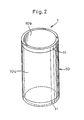
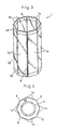
- a plurality of plate-shaped ceramic heaters 1a are arranged in the shape of a prism which is polygonal in cross section (eight-sided polygonal in Figs. 3 and 4) as shown in Figs. 3 and 4 can be used in addition to one so adapted that the whole is integrally formed of a conductive ceramic material as shown in Fig. 2.
- INFRALEX-BIRRC (trade name) manufactured by Asahi Glass Co., Ltd. is commercially available. This is constructed by sintering a mixture of a ceramic material and a metal material to form a cylinder body 10 or a plate body 12 made of conductive ceramics as well as laminating a metal material such as aluminium in the outer periphery in both ends of the cylinder body 10 or in both ends of the plate body 12 in a strip shape by a flame spray coating process, various gas phase processes, a wet plating process or the like to form a pair of electrodes 11 or 13.
- the object to be heat-treated (body 1) is heated by radiating far infrared rays having a wavelength of approximately 2.5 to 25 ⁇ m from the outer periphery 10a and the inner periphery 10b of the cylinder body 10 or the outer surface of the plate body 12.
- the above described directly energized ceramic infrared heater can uniformly heat the surface of the body P serving as the object to be heat-treated contained inside thereof because the cylinder body 10 or the plate body 12 itself is a uniform heating element having conductive properties and a portion other than both the ends where the electrodes are formed uniformly generates heat if a voltage is applied between the pair of electrodes 11 or 13.
- the above directly energized ceramic infrared heater 1 has the advantage that the heating rate or the like can be finely controlled as described later because it is superior in response to applied power.
- the directly energized ceramic infrared heater 1 shown in Fig. 2 comprises a seamless cylinder body 10 which is almost uniformly made of a conductive ceramic material throughout and a pair of annular electrodes 11 provided on both ends of the cylinder body 10, as described above.
- the spacing in the radial direction between an inner peripheral surface 10b of the above directly energized ceramic infrared heater 1 and an outer peripheral surface of the body P is not particularly limited, which preferably is in the range of 5 to 300 mm and particularly, in the is in the range of 5 to 300 mm and particularly, in the range of 10 to 100 mm.
- the spacing in the radial direction between the inner peripheral surface 10b of the directly energized ceramic infrared heater 1 and the outer peripheral surface of the body P is less than 5 mm, the distance therebetween is too short. Accordingly, any non-uniformity in heat generation in the directly energized ceramic infrared heater 1 would adversely affect the dry state of a coating film of the body P directly, so that the coating film is not uniformly dried.
- the density of vapors of solvent evaporated from the coating film is high. Accordingly, if drying air is circulated between the directly energized ceramic infrared heater 1 and the body P as described later, defects such as vertical reinforcement may occur on the surface of the coating film due to the flow of the vapors of the solvent. On the other hand, when the spacing in the radial direction between the inner periphery of the directly energized ceramic infrared heater 1 and the outer periphery of the body P exceeds 300 mm, the distance therebetween is too long, resulting in heat loss. Accordingly, energy more than necessary may be consumed so as to dry the coating film.
- the cylinder body 10 is seamless and is formed almost uniformly throughout. Accordingly, it has the advantage that if a voltage is applied between the pair of electrodes 11 as described above, a portion other than both the ends where the electrodes 11 are formed uniformly generates heat, thereby to make it possible to uniformly dry the coating film on the surface of the body 1.
- the directly energized ceramic infrared heater 1 shown in Figs. 3 and 4 is constructed by arranging a plurality of plate-shaped ceramic heaters 1a each having a plate body 12 almost uniformly formed of a conductive ceramic material and a pair of electrodes 13 provided in both ends of the plate body 12 in the shape of a prism which is polygonal in cross section.
- the plate-shaped ceramic heaters 1a are arranged in the shape of a prism with clearances g being provided therebetween as shown in Figs. 3 and 4 so as to prevent leakage of a current.
- the clearances g can be also used with they not being blocked so as to efficiently remove vapors of solvent emitted from a coating film as described above.
- the clearances g are preferably blocked by an insulating material such as rubber or a heat insulating material as described later and the like in consideration of thermal efficiency and uniform heating.
- the number of angles of the polygon is not particularly limited.
- an object to be heat-treated is a cylinder body or a pillar body such as a body P of a photosensitive drum, however, it is preferable that the above number of angles is six or more.
- the difference in the spacing in the radial direction between the inner peripheral surface of the directly energized ceramic infrared heater 1 and the outer peripheral surface of the cylinder body or the pillar body in a vertex of the polygon and the center of a side thereof becomes large, so that there is a possibility that the object to be heat-treated is not uniformly heated.
- the directly energized ceramic infrared heater 1 is constituted by the plurality of plate-shaped ceramic heaters 1a as described above, each of the plate-shaped ceramic heaters 1a is manufactured more easily and can be formed to be thinner than the cylinder body. Accordingly, the directly energized ceramic infrared heater 1 can be manufactured at low cost and to be lightweight. Consequently, there are some advantages. For example, the whole of the above directly energized ceramic infrared heater 1 can be manufactured at low cost, combined with possible simplification of, for example, means for moving the above directly energized ceramic infrared heater 1 up and down to a conveying path of the body P (an up-and-down device as described later).
- the directly energized ceramic infrared heater 1 and the body P can be relatively rotated at the time of heating so as to further ensure uniformity in heating.
- the rotation speed of the directly energized ceramic infrared heater 1 or the body P is not particularly limited, which preferably is in the range of 5 to 40 r.p.m. If the rotation speed is less than 5 r.p.m., heating may be non-uniform. Contrary to this, if the rotation speed exceeds 40 r.p.m., air caused by the rotation may affect the coating film, and it may be difficult to control and maintain high-speed rotation.
- the cylindrical directly energized ceramic infrared heater 1 is constituted by the plurality of plate-shaped ceramic heaters 1a as described above, the widths of the plate-shaped ceramic heater 1a and the clearance g, the spacing between the above plate-shaped ceramic heater 1a and the surface of the body P serving as the object to be heat-treated, and the like can be suitably selected to preferred numerical values depending on the diameter of the body, the number of angles of the directly energized ceramic infrared heater 1, and the like.
- the body P is heat-treated by the directly energized ceramic infrared heater 1 in the shape of a prism which is eight-sided polygonal in cross section shown in Figs.
- the plate-shaped ceramic heaters 1a are arranged in the shape of an eight-sided polygon with the width of the clearances g being 1 mm or more such that the shortest distance between the inner wall surface of the plate-shaped ceramic heater 1a and the outer peripheral surface of the body P (represented by a sign d in Fig. 4) is 5 mm or more.
- the distance therebetween is too short. Accordingly, any non uniformity in heat generation in the plate-shaped ceramic heter 1a would adversely affect the dry state of the coating film of the body P directly, so that the coating film is not uniformly dried.
- the density of the vapors of the solvent evaporated from the coating film is high. Accordingly, if drying air is circulated between the directly energized ceramic infrared heater 1 and the body P as described later, defects such as vertical reinforcement are liable to occur on the surface of the coating film due to the flow of the vapors of the solvent.
- a seamless tubular or bar-shaped directly energized ceramic infrared heater 9 having an outside diameter smaller than the inside diameter of the body P may be arranged concentrically with the directly energized ceramic infrared heater 1, as shown in Figs. 5 and 6 or 7 and 8.
- the above directly energized ceramic infrared heater 9 is inserted in the body P when the body P is contained in the cylindrical directly energized ceramic infrared heater 1 and is used for heating the body P from the inside and outside, as shown in Fig.
- a wavelength cutting filter for transmitting only a component in a particular wave range which can pass through the coating film of far infrared rays radiated from the cylindrical directly energized ceramic infrared heater 1 opposed to the surface of the body P having the coating film formed thereon and cutting the other components may be interposed between at least the directly energized ceramic infrared heater 1 out of the above directly energized ceramic infrared heaters 1 and 9 and the above body P.
- ND filters Neutral Density Filters
- the wave range of the far infrared rays to be transmitted by the above wavelength cutting filter differs depending on the thickness of the coating film, as described above. For example, when the thickness of the coating film is approximately 5 to 40 ⁇ m, the particular wave range is in the range of 25 to 1000 ⁇ m.
- the directly energized ceramic infrared heater 1 described in the foregoing is attached to a mounting seat 51 in a forward end of an up-and-down bar 5 serving as the up-and-down device, as shown in Figs. 1 and 9, to be arranged movably up and down to the conveying path of the body P in the thermal treatment equipment shown in Fig. 1.
- blast tubes 6 serving as ventilating means are connected to the above described mounting seat 51, as shown in Fig. 9.
- the ventilating means is used for causing drying air to flow down from the upper and to the lower end of the body P to prevent the solvent evaporated from the coating film from staying in the directly energized ceramic infrared heater 1 to efficiently dry the coating film.
- the flow rate of the drying air is preferably in the range of 0.01 to 3 m/sec and particularly, in the range of 0. 1 to 2 m/sec. If the flow rate of the drying air is less than 0.01 m/sec, the solvent evaporated from the coating film cannot be sufficiently prevented from staying in the directly energized ceramic infrared heater 1. Contrary to this, when the flow rate of the drying air exceeds 3 m/sec, the temperature of the directly energized ceramic infrared heater itself is lowered, which may reduce radiation efficiency.
- the drying air is turbulent flow, the coating film is liable to be non-uniform.
- the drying air is upper flow from the lower end to the upper end of the body P, the difference in temperature appears between the lower end and the upper end of the body P, so that the coating film may not be uniformly dried. Consequently, the drying air is preferably down flow from the upper end to the lower end of the body P.
- the pallet 3 conveyed along the conveying path on a conveying rail 2 comprises a pillar-shaped convex portion 31 having a fitting groove 31a to which the lower end of the body P is fitted for holding the body P in an upright state and a fitting concave portion 32 to which the lower end of the directly energized ceramic infrared heater 1 lowered on the conveying path is fitted for concentrically holding the body P and the directly energized ceramic infrared heater 1, as shown in Fig. 10.
- a stepped portion represented by ⁇ in Fig. 10 is provided between the bottom surface of the above fitting groove 31a and the bottom surface of the fitting concave portion 32 so as to hold the body P in a region other than a non-heated region (in the range represented by ⁇ in Fig. 10) which corresponds to the above described electrode in the lower end of the directly energized ceramic infrared heater 1.
- the directly energized ceramic infrared heater 1 comprises the ventilating means for circulating the drying air from the upper end to the lower end of the body P, as described above. Accordingly, as shown in Fig. 10, in the palette 3, a plurality of vent holes 33 through which the drying air supplied from the ventilating means is passed are arranged on the bottom surface of the above fitting concave portion 32 so as to surround the convex portion 31.
- the cooling means 4 is used for preventing the coating film from being rapidly heated by covering the next body P with the directly energized ceramic infrared heater 1 which has heated the body P in a high temperature state, which comprises a cylindrical main body 41 containing the directly energized ceramic infrared heater 1 and a door 42 for closing an opening in the lower end of the cylindrical main body 41, as shown in Fig. 1. If the directly energized ceramic infrared heater 1 is raised to be contained in the main body 41, as represented by a solid line in Fig. 1, the door 42 is closed and then, cooling air is supplied from ventilating means (not shown) to the main body 41 so that the directly energized ceramic infrared heater 1 is cooled.
- the directly energized ceramic infrared heater 1 comprises the ventilating means for circulating the drying air from the upper end to the lower end of the body P as described above, drying air can be also used as cooling air for cooling the directly energized ceramic infrared heater 1 in the cooling means 4.
- thermal treatment equipment shown in Fig. 11.
- This thermal treatment equipment is the same as the above described thermal treatment equipment shown in Fig. 1 except that a plurality of heat insulating materials 7 for surrounding a directly energized ceramic infrared heater 1 at the time of heating a body P are arranged detachably from the above directly energized ceramic infrared heater 1.
- the thermal treatment equipment shown in Fig. 11 comprises a plurality of pallets 3 conveyed on a conveying rail 2 with the body P being held in an upright state, a cylindrical directly energized ceramic infrared heater 1 arranged movably up and down to a conveying path of the body P by the pallets 3 for heating the body P from the periphery with the body P being concentrically contained therein in its lowered state, and cooling means 4 for cooling the directly energized ceramic infrared heater 1 raised from the conveying path with the directly energized ceramic infrared heater 1 being contained therein.
- the heat insulating materials 7 are used for trapping heat of the directly energized ceramic infrared heater 1 to heat the body P more efficiently and has such a shape that a cylinder body having an inside diameter conforming to the outer periphery of the above directly energized ceramic infrared heater 1 is divided (divided into four parts in Figs. 12 and 13) along the direction of its axis, as shown in Figs. 12 and 13.
- the whole of the above heat insulating materials 7 is formed of a heat-resistant heat insulating material, for example, a fiber having a diameter of approximately 3 mm comprising mica and a ceramics material.
- the above heat insulating materials 7 are firmly bonded to the outer periphery of the above directly energized ceramic infrared heater 1 (see Fig. 12) at the time of heating the body P by the directly energized ceramic infrared heater 1.
- the heat insulating materials 7 are separated from the directly energized ceramic infrared heater 1 to be cooled by themselves so as not to prevent the directly energized ceramic infrared heater 1 from being cooled (see Fig. 13).
- Cooling means 8 for cooling the heat insulating materials 7 separated from the directly energized ceramic infrared heater 1 by themselves is arranged beneath the conveying rail 2, as shown in Fig. 11, and cooling air is supplied from ventilating means (not shown) to cool the heat insulating materials 7.
- cooling pipe 81 inserted in each of the heat insulating materials 7 for cooling the heat insulating material 7 by circulating a refrigeration medium such as cooling water.
- Materials of the cooling pipe 81 include polytetrafluoroethylene (Teflon, whose heat resistance is 260 °C or less), silicone resin (whose heat resistance is 260 °C or less), fluororubber (whose heat resistance is 300 °C or less) and the like.
- thermal treatment equipment shown in Fig. 14.
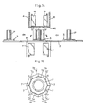
- the thermal treatment equipment is the same as the above described thermal treatment equipments except that eight plate-shaped ceramic heaters 1a are arranged in the shape of a prism as described above to construct a cylindrical directly energized ceramic infrared heater 1, and the plate-shaped ceramic heaters 1a are divided into four blocks 1b two by two as shown in Fig. 15 and are separately cooled in a main body 41 of cooling means 4 at the time of cooling.
- the thermal treatment equipment shown in Fig. 14 is the same as the above described thermal treatment equipment shown in Fig. 11 except for the foregoing. More specifically, the thermal treatment equipment shown in Fig. 14 comprises a plurality of pallets 3 conveyed on a conveying rail 2 with a body P being held in an upright state, a cylindrical directly energized ceramic infrared heater 1 arranged movably up and down to a conveying path of the body P by the pallets 3 for heating the body P from the periphery with the body P being concentrically contained therein in its lowered state, cooling means 4 for cooling the directly energized ceramic infrared heater 1 raised from the conveying path with the directly energized ceramic infrared heater 1 being contained therein, and a plurality of heat insulating materials 7 for surrounding the directly energized ceramic infrared heater 1 assembled in a cylindrical shape at the time of heating the body P.
- each of the above described heat insulating materials 7 is arranged corresponding to one block 1b comprising two plate-shaped ceramic heaters 1a, as shown in Fig. 15.
- the heat insulating materials 7 are divided into four parts along with the blocks 1b, as indicated by white arrows in Fig. 15 and then, separated from the blocks 1b to be cooled by themselves in cooling means 8 arranged beneath the conveying rail, as indicated by black arrows in Fig. 14.
- the thermal treatment equipment shown in Fig. 14 comprising the above described parts has the advantage that the directly energized ceramic infrared heater 1 can be cooled more efficiently because it is cooled with it being divided into a plurality of blocks 1b.
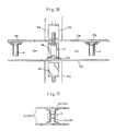
- the thermal treatment equipment is the same as the above described three thermal treatment equipments except that there are provided two conveying rails 2a and 2b on upper and lower sides for alternately conveying a plurality of bodies P, and there are provided two cylindrical directly energized ceramic infrared heaters 1A and 1B with the two conveying rails 2a and 2b being interposed therebetween.
- the two directly energized ceramic infrared heaters 1A and 1B are alternately raised and lowered to alternately heat the bodies P alternately conveyed on the above two conveying rails 2a and 2b.
- the plurality of bodies P are alternately conveyed by a pallet 3a moving on the conveying rail 2a on the lower side and a pallet 3b moving on the conveying rail 2b on the upper side.
- the directly energized ceramic infrared heater 1A on the upper side is lowered and concentrically contains the body P held on the above pallet 3a, as shown in Fig. 16, to heat and dry its coating film.
- the directly energized ceramic infrared heater 1B on the lower side is contained in cooling means 4b beneath the conveying rail 2a on the lower side to be cooled.
- the directly energized ceramic infrared heater 1A on the upper side is terminated, the directly energized ceramic infrared heater 1A is raised and is contained in cooling means 4a on the conveying rail 2b on the upper side to be cooled, as represented by a two-dot and dash line in Fig. 16.
- the body P which has been dried is conveyed from between the two directly energized ceramic infrared heaters 1A and 1B by the movement of the pallet 3a and then, the pallet 3b on the upper side holding the body P which has not been treated yet is moved to enter between the above two cylindrical directly energized ceramic infrared heaters 1A and 1B.
- the directly energized ceramic infrared heater 1B on the lower side is raised and concentrically contains the body P held on the above pallet 3b, to heat and dry its coating film.
- a gauge G between the above conveying rails 2a and 2b is set to be wider than the outside diameter of each of the directly energized ceramic infrared heaters 1A and 1B, as shown in Fig. 17. Consequently, the up-and-down movement of the directly energized ceramic infrared heaters 1A and 1B to the conveying rails 2a and 2b is not prevented by the conveying rails 2a and 2b.
- the above described thermal treatment equipment shown in Fig. 16 has the advantage that waiting time for cooling the directly energized ceramic infrared heater can be omitted and a photosensitive drum can be dried more efficiently because one of the directly energized ceramic infrared heters can be cooled while drying the body P by the other directly energized ceramic infrared heater.
- a method of drying a photosensitive layer of a photosensitive drum serving as a functional thin film using each of the above described thermal treatment equipments a method is employed in which the body P is concentrically contained once in the directly energized ceramic infrared heater 1 cooled by the cooling means 4 and then, this directly energized ceramic infrared heater 1 is energized to generate heat, to raise the body P from the room temperature to a predetermined heating temperature, and the body P is heated for a predetermined time period to dry the coating film of the polymer coating fluid formed on the surface of the above body P, as described above.
- the coating film formed by applying the polymer coating fluid on the surface of the body P is dried by predetermined natural drying and then, is dried by the directly energized ceramic infrared heater 1 so as to make the state of the coating film constant.
- the coating film can be uniformly dried to the inside thereof, thereby to make it possible to form a photoreceptor which is free from defects such as orange peel, bubbles and pinholes and has a stable performance because the amount of the remaining solvent is small.
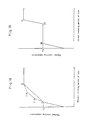
- a temperature rise pattern shown in Fig. 18 is such a pattern that the body P is rapidly raised to the glass transmission temperature of the coating film (represented by Point I in Fig. 18), the body P is gradually raised to a predetermined heating temperature by decreasing the heating rate from the glass transmission temperature on, the temperature rise of the body P is stopped in the stage in which the body P reaches the predetermined heating temperature (represented by Point II in Fig. 18), and the above temperature is maintained until drying is terminated.
- the same heating rate may be maintained as represented by a solid line in Fig. 18 from the above point I to the above point II.
- control may be so carried out that the heating rate is decreased by stages through several points of inflection (two points of inflection, that is, Point I-a and Point I-b) as represented by a one dot and dash line in Fig. 18.
- points of inflection two points of inflection, that is, Point I-a and Point I-b
- the above point I and the above point II may be connected in a curve shape, which is not shown.
- a temperature rise pattern shown in Fig. 19 is such a pattern that the body P is rapidly raised to the glass transmission temperature of the coating film (Point III in Fig. 19), the temperature rise is stopped for a predetermined time period at the glass transmission temperature (to Point IV in Fig. 19) and then, the body P is raised again to a predetermined heating temperature, the temperature rise is stopped again in the stage in which the body P reaches the predetermined heating temperature (Point V in Fig. 19), and the above temperature is maintained until drying is terminated.
- a control device for controlling heating of the body P by the directly energized ceramic infrared heater 1 by stages as in the above described two examaples one of construction shown in, for example, Fig. 20 is adopted.
- the control device shown in Fig. 20 comprises an SCR unit U2 for controlling driving power supplied to the directly energized ceramic infrared heater 1 from the power supply on the basis of an instruction from temperature adjusting means U1, an inverter U3 for controlling the driving of a fan F for supplying drying air to the directly energized ceramic infrared heater 1, and a sequencer U4 for controlling the above temperature adjusting means U1 and the inverter U3.
- the sequencer U4 stores data, such as the procedure of the temperature control of the body P by the directly energized ceramic infrared heater 1, timing at which the fun F is rotated, or the glass transmission temperature of a polymer material in the coating film and is used for controlling the above temperature adjusting means U1 and the inverter U3 on the basis of this data.
- a temperature sensor C for measuring the temperature of the above body P in controlling heating of the body P using the directly energized ceramic infrared heater 1 by stages by controlling the SCR unit U2 on the basis of an instruction from the sequencer U4 to adjust power supplied to the directly energized ceramic infrared heater 1 is connected to the above temperature adjusting means U1.
- control signals are sequentially sent to the temperature adjusting means U1 and the inverter U3 from this sequencer U4 on the basis of the data previously store d.
- the temperature adjusting means U1 receiving the control signal from the sequencer U4 controls the SCR unit U2 while measuring the temperature of the body P by the temperature sensor C to control the heating temperature of the body P using the directly energized ceramic infrared heater 1 by stages as shown in Fig. 18 or 19, and the inverter U3 receiving the control signal from the sequencer U4 drives the fan F according to the procedure to dry the body P.
- the thermal treatment equipment according to the present invention is constructed as described above, and the object to be heat-treated is heated with it being concentrically contained in the cylindrical directly energized ceramic infrared heater, thereby to make it possible to uniformly heat-treat the object to be heat-treated.
- thermal treatment equipment Consequently, by using the thermal treatment equipment according to the present invention, a space and cost for installation, time required for heat treatment, consumed energy and the like can be significantly cut.
- the surface of the coating film can be prevented from being dried prior to the inside thereof to uniformly dry the coating film to the inside thereof by slowly raising the temperature or temporarily stopping the temperature rise from the glass transmission temperature of the coating film on, thereby to make it possible to form a uniform functional thin film which is free from defects such as orange peel, bubbles, pinholes and cissing and is small in internal stress.
- thermal treatment equipment and the method of drying a functional thin film according to the present invention are not limited to the foregoing examples.
- the directly energized ceramic infrared heater is moved up and down to the conveying path of the body P, the body P may be conversely moved up and down.
- the pallets 3, the conveying rail 2, the cooling means 4, the up-and-down bar 5 serving as the up-and-down device, the blast tubes 6 serving as the ventilating means, the heat insulating materials 7, the cooling means 8 and the like are provided so as to dry the body P more efficiently, the members are not necessarily required for the present invention.
- the constituent elements other than at least the cylindrical directly energized ceramic infrared heater are not particularly limited.
- thermal treatment equipment for drying a photosensitive layer of a photosensitive drum serving as a functional thin film
- the thermal treatment equipment according to the present invention can be used for other applications such as formation of the other functional thin films, annealing of a plated film or a deposited film formed on the surface of the substrate, sintering of ceramics formed in a pillar shape or a cylindrical shape, and hardening of metal.
- the object to be heat-treated is a cylindrical photosensitive drum. Accordingly, as the directly energized ceramic infrared heater, one in the shape of a cylinder or a prism which is not less than six-sided polygonal in cross section is used. However, when an object to be heat-treated having the other cross sectional shape is heat-treated, a cylindrical directly energized ceramic infrared heater having a cross sectional shape most suitable for uniformly heating the object to be heat-treated may be used.
- temperature control after reaching a predetermined heating temperature is not particularly limited.
- the method of drying a functional thin film according to the present invention can be applied to drying of functional thin films other than a photosensitive layer, for example, an energized exothermic coating film made of an energized exothermic coating having heating elements dispersed in an organic matrix.
- compositions are mixed and dispersed using a ultrasonic dispersion mixer, to prepare a polymer coating fluid for a single-layer type photosensitive layer.
- the above described polymer coating fluid is then applied to the surface of an aluminum body having an outside diameter of 78 mm and having an entire length of 344 mm by dipping and is naturally dried at room temperature (20 °C) for three minutes, to form a coating film having a thickness of 22 ⁇ m.
- the above body is concentrically contained in a seamless cylindrical directly energized ceramic infrared heater having an inside diameter of 197 mm and having an entire length of 450 mm, and is raised from the room temperature (20 °C) to the glass transmission temperature of the above coating film (62 °C) in thirty seconds (Point I in Fig. 18) and then, is raised to 100 °C in 141 seconds from the start of heating by decreasing the heating rate (Point II in Fig. 18) in accordance with a pattern linearly connecting the point I and the point II, represented by a solid line in Fig. 18, out of temperature rise patterns shown in Fig. 18. Thereafter, the coating film is dried for ten minutes from the start of heating while maintaining the above described temperature of 100°C to form a single-layer type photosensitive layer on the surface of the body, thereby to fabricate a photosensitive drum.
- a photosensitive drum is fabricated in the same manner as the above described example 1 except that a coating film is dried by a directly energized ceramic infrared heater in accordance with the following temperature rise pattern.
- the body is raised from the room temperature (20 °C) to the glass transmission temperature of the above coating film (62 °C) in thirty seconds (Point I in Fig. 18) and the n, is raised to 79°C in 51 seconds from the start of heating by decreasing the heating rate (Point I-a in Fig. 18), is raised to 93 °C in 90 seconds from the start of heating (Point I-b in Fig. 18) and then, is raised to 100°C in 141 seconds from the start of heating by further decreasing the heating rate (Point II in Fig. 18) in accordance with a pattern having two points of inflection I-a and I-b provided between the point I and the point II, as represented by a one dot and dash line, out of the temperature rise patterns shown in Fig. 18. Thereafter, the coating film is dried for ten minutes from the start of heating while maintaining the above described temperature of 100°C.
- a photosensitive drum is fabricated in the same manner as the above described example 1 except that a coating film is dried by a directly energized ceramic infrared heater in accordance with the following temperature rise pattern.
- the body is raised from the room temperature (20 °C) to the glass transmission temperature of the above coating film (62 °C) in thirty seconds (Point III in Fig. 19) and then, the temperature rise is stopped to maintain the above described temperature of 62°C until 330 seconds are elapsed from the start of heating (Point IV in Fig. 19) in accordance with a temperature rise pattern shown in Fig. 19.
- the temperature rise is then started again to raise the body to 100 °C in 390 seconds from the start of heating (Point V In Fig. 19). Thereafter, the coating film is dried for ten minutes from the start of heating while maintaining the above described temperature of 100 °C.
- a photosensitive drum is fabricated in the same manner as the above described example 1 except that used as a directly energized ceramic infrared heater is one which is eight-sided polygonal in cross section comprising eight plate-shaped ceramic heaters having a width of 70 mm and having an entire length of 450 mm (manufactured by Asahi Glass Co., Ltd., INFRALEX-BIRRC (trade name)) and clearances having a width of 2 mm blocked by insulating rubber (d in Fig. 4 is 47 mm), and a coating film is dried while rotating a body at a rotation speed of 20 r.p.m. relatively to the above directly energized ceramic infrared heater.
- a directly energized ceramic infrared heater is one which is eight-sided polygonal in cross section comprising eight plate-shaped ceramic heaters having a width of 70 mm and having an entire length of 450 mm (manufactured by Asahi Glass Co., Ltd., INFRALEX-BIRRC
- a photosensitive drum is fabricated in the same manner as the above described example 4 except that the same temperature rise pattern as that in the example 2 is used.
- a photosensitive drum is fabricated in the same manner as the above described example 4 except that the same temperature rise pattern as that in the example 3 is used.
- a photosensitive drum is fabricated in the same manner as the above described example 1 except that a coating film is dried by a directly energized ceramic infrared heater in accordance with the following temperature rise pattern.
- the body is linearly raised from the room temperature (20°C) to 100°C in ten seconds and then, the coating film is dried for ten minutes from the start of heating while maintaining the above described temperature of 100°C.
- a photosensitive drum is fabricated in the same manner as the above described example 1 except that a coating film is dried at 100 °C for thirty minutes using a conventional drier shown in Figs. 21 and 22.
- Each of the photosensitive drums is fitted in an electrostatic copying testing device (manufactured by Jentech Co., Ltd., Jentech Sinsia 30M) and the surface thereof is positively charged, to measure a surface potential V1s.p. (V).
- Each of the above described photosensitive drums in a charged state is exposed using a halogen lamp which is a light source for exposure of the above electrostatic copying testing device, and time elapsed until the above surface potential V1 s.p. (V) is reduced by half is found to calculate the amount of exposure reduced by half E1/2 ( ⁇ J/cm2).
- Each of the above described drums is fitted in an electrophotographic copying machine (of a DC-1656 type, which is manufactured by Mita Industrial Co., Ltd.) to make 300 copies and then, the surface potential is measured as a surface potential after repeated exposure V2 s.p. (V).
- the photosensitive drum fabricated in each of the above described examples is fitted in the electrophotographic copying machine (of a DC-1656 type, which is manufactured by Mita Industrial Co., Ltd.) to make 500 copies and then, each photoreceptor is cut into respective 16 checkers 1 mm square and 5 mm square by a cutting knife, and a peel test is carried out using a Nichiban tape (trademark) to observe peeling from the photoreceptor.
- the numbers of checkers which are not peeled from the photoreceptor out of the above checkers 1 mm square and 5 mm square are respectively recorded. The foregoing results are shown in the following table:
- the results of the foregoing table are as follows: In the example 7 in which the body is raised linearly and rapidly from the room temperature to 100°C, a lot of defects such as bubbles, pinholes and cissing are observed in the photosensitive layer, that is, the photosensitive layer is inferior in state, thereby to make it impossible to measure photosensitivity and adhesion of the photosensitive layer to the surface of the body. Furthermore, in the example 8 in which the coating film is dried using the conventional drier, the photosensitive drum is inferior in photosensitivity and adhesion of the photosensitive layer to the surface of the body. Moreover, when the photosensitive layer is observed, pinholes and a skinning phenomenon are observed.
- the photosensitive drums obtained in the examples 1 to 6 are all superior in photosensitivity as well as adhesion of the photosensitive layer to the surface of the body to those in the examples 7 and 8. Moreover, when the photosensitive layer in each of the examples is observed, no bubbles, pinholes, cissing and the like are observed, so that it is confirmed that the photosensitive layer is a superior layer being free from defects. This proves that the coating film can be uniformly and sufficiently dried to the inside thereof, thereby to make it possible to form a photosensitive layer which is free from defects, is uniform and is small in internal stress in the above described examples 1 to 6.
- the photosensitive drum in the example 3 in which the temperature rise is stopped once from the glass transmission temperature on is smallest in internal stress and has a photosensitive layer superior in adhesion. Consequently, it is presumed that the amount of the solvent remaining in the photosensitive layer can be minimized in accordance with such a temperature rise pattern as in the above described example 3.
- the amount of the solvent remaining in the coating film is measured at random by a pyrolysis chromatograph. This measurement indicates that the amount of the solvent remaining in 1 mg of the coating film is decreased to 5 x 10 ⁇ 3 to 1 ⁇ l/mg in a state where the temperature rise is stopped, that is, from the point III to the point IV in Fig. 19 and then, the amount of the solvent remaining in the photosensitive layer formed can be made zero by the rapid temperature rise.
- the thermal treatment equipment according to the present invention is suitable for, for example, formation of a functional thin film by drying a polymer coating fluid applied to the surface of a pillar-shaped or cylindrical substrate, annealing of a plated film or a deposited film formed on the surface of the substrate, sintering of ceramics formed in a pillar shape or a cylindrical shape, and hardening of metal because it can uniformly heat-treat an object to be heat-treated.
- a method of drying a functional thin film according to the present invention is suitable for drying of a functional thin film such as a photosensitive layer of a photosensitive drum or an energized exothermic coating film made of an energized exothermic coating having heating elements dispersed in an organic matrix because the surface of the coating film can be prevented from being dried prior to the inside thereof to uniformly dry the coating film to the inside thereof.
Landscapes
- Engineering & Computer Science (AREA)
- Chemical & Material Sciences (AREA)
- Combustion & Propulsion (AREA)
- Life Sciences & Earth Sciences (AREA)
- Microbiology (AREA)
- Mechanical Engineering (AREA)
- General Engineering & Computer Science (AREA)
- Ceramic Engineering (AREA)
- Resistance Heating (AREA)
- Drying Of Solid Materials (AREA)
- Photoreceptors In Electrophotography (AREA)
Abstract
Dispositif de traitement thermique pourvu d'un élément chauffant céramique cylindrique à infrarouges extrêmes alimenté directement, servant à chauffer un objet cylindrique ou en forme de colonne destiné à être traité, qui est concentrique à l'élément chauffant qui l'entoure. Ce dispositif permet d'effectuer un traitement thermique uniforme d'un objet. On décrit également un procédé de séchage d'une pellicule de revêtement composée d'un liquide de revêtement polymère formée à la surface d'un substrat cylindrique ou en forme de colonne, grâce à une configuration chauffante spécifique obtenue par l'utilisation du dispositif de traitement thermique décrite. Ce procédé de séchage empêche que la surface de la pellicule de revêtement ne sèche avant la partie interne, de manière à obtenir un séchage uniforme également de la partie interne de la pellicule de revêtement.
Applications Claiming Priority (4)
| Application Number | Priority Date | Filing Date | Title |
|---|---|---|---|
| JP308385/89 | 1989-11-28 | ||
| JP30838589 | 1989-11-28 | ||
| JP2004824A JPH03233885A (ja) | 1989-11-28 | 1990-01-12 | 熱処理装置およびこれを用いた機能性薄膜の乾燥方法 |
| JP4824/90 | 1990-01-12 |
Publications (2)
| Publication Number | Publication Date |
|---|---|
| EP0456829A1 true EP0456829A1 (fr) | 1991-11-21 |
| EP0456829A4 EP0456829A4 (en) | 1992-05-13 |
Family
ID=26338667
Family Applications (1)
| Application Number | Title | Priority Date | Filing Date |
|---|---|---|---|
| EP19900917342 Withdrawn EP0456829A4 (en) | 1989-11-28 | 1990-11-26 | Heat-treatment device and method of drying functional thin film using said device |
Country Status (4)
| Country | Link |
|---|---|
| EP (1) | EP0456829A4 (fr) |
| JP (1) | JPH03233885A (fr) |
| KR (1) | KR920702179A (fr) |
| WO (1) | WO1991008655A1 (fr) |
Cited By (7)
| Publication number | Priority date | Publication date | Assignee | Title |
|---|---|---|---|---|
| WO1995012102A1 (fr) * | 1993-10-28 | 1995-05-04 | Bayerische Motoren Werke Aktiengesellschaft | Procede pour le sechage de peintures d'automobiles |
| FR2869831A1 (fr) * | 2004-05-06 | 2005-11-11 | Heights France Sas Soc Par Act | Procede de sechage-desorption de plaques de flexogravure par exposition a un rayonnement en l'absence de circulation d'air chaud, et enceinte de mise en oeuvre du procede |
| EP2071260A1 (fr) * | 2007-12-13 | 2009-06-17 | EISENMANN Anlagenbau GmbH & Co. KG | Dispositif de séchage d'objets, en particulier de carrosseries de véhicules peintes |
| US7560217B2 (en) | 2004-12-09 | 2009-07-14 | Sharp Kabushiki Kaisha | Method of forming electrophotographic photoreceptor and method of drying coating film |
| US9904186B2 (en) | 2011-08-05 | 2018-02-27 | Fuji Electric Co., Ltd. | Electrophotographic photoreceptor, method for manufacturing same, and electrophotographic apparatus using same |
| US11840609B1 (en) * | 2023-04-12 | 2023-12-12 | King Faisal University | Method to prepare superhydrophobic sheets from virgin and waste polypropylene |
| EP4343248A1 (fr) * | 2022-09-23 | 2024-03-27 | Duo Technik GmbH | Dispositif pour sécher des articles plats |
Families Citing this family (3)
| Publication number | Priority date | Publication date | Assignee | Title |
|---|---|---|---|---|
| JP4654131B2 (ja) * | 2006-02-07 | 2011-03-16 | 株式会社リコー | 表面層加熱処理装置、表面層加熱・急冷処理装置 |
| JP4824495B2 (ja) * | 2006-07-18 | 2011-11-30 | 株式会社リコー | 連続加熱処理装置 |
| JP6020679B2 (ja) * | 2015-07-15 | 2016-11-02 | 富士電機株式会社 | 電子写真用感光体、その製造方法およびそれを用いた電子写真装置 |
Family Cites Families (15)
| Publication number | Priority date | Publication date | Assignee | Title |
|---|---|---|---|---|
| GB323690A (en) * | 1929-03-21 | 1930-01-09 | Albert Boecler | Improvements in or relating to apparatus for the continuous drying of webs |
| US2315124A (en) * | 1942-09-03 | 1943-03-30 | Park Chem Co | Drying machine |
| FR951180A (fr) * | 1947-07-30 | 1949-10-18 | Séchoir électrique à lampes pour flans de clicherie | |
| US2660723A (en) * | 1951-03-06 | 1953-12-01 | Delamarre Emile Jules | Apparatus for the stabilization of ivory |
| FR1098620A (fr) * | 1954-01-19 | 1955-08-16 | Gallet & Cie | Perfectionnements aux séchoirs pour objets de grandes dimensions |
| JPS5216055U (fr) * | 1975-07-23 | 1977-02-04 | ||
| JPS59123180A (ja) * | 1982-12-24 | 1984-07-16 | ソ−ン イ−エムアイ ドメスティック アプライアンス リミテッド | 加熱装置 |
| DE3482175D1 (de) * | 1983-11-02 | 1990-06-13 | American Screen Printing | Trockenapparat mit auswerfmechanismus. |
| US4813153A (en) * | 1985-02-25 | 1989-03-21 | Palmer Arthur R | Ink drying apparatus |
| JPS61203292U (fr) * | 1985-06-07 | 1986-12-20 | ||
| JPS62241286A (ja) * | 1986-04-10 | 1987-10-21 | 真空理工株式会社 | 赤外線加熱炉 |
| JPS6330360A (ja) * | 1986-06-04 | 1988-02-09 | 工業技術院長 | 酸化第二鉄焼結体及びセラミツクス赤外線ヒ−タ |
| US4967487A (en) * | 1988-04-25 | 1990-11-06 | Urquhart Gordon T | Oven for the curing and cooling of painted objects and method |
| JPH01289087A (ja) * | 1988-05-14 | 1989-11-21 | Toho Rayon Co Ltd | 繊維の加熱処理装置 |
| EP0367867A1 (fr) * | 1988-11-09 | 1990-05-16 | Classic Sanitär-Produkte Gmbh | Dispositif pour chauffer des pièces relativement petites |
-
1990
- 1990-01-12 JP JP2004824A patent/JPH03233885A/ja active Pending
- 1990-11-26 WO PCT/JP1990/001535 patent/WO1991008655A1/fr not_active Ceased
- 1990-11-26 KR KR1019910700785A patent/KR920702179A/ko not_active Withdrawn
- 1990-11-26 EP EP19900917342 patent/EP0456829A4/en not_active Withdrawn
Cited By (7)
| Publication number | Priority date | Publication date | Assignee | Title |
|---|---|---|---|---|
| WO1995012102A1 (fr) * | 1993-10-28 | 1995-05-04 | Bayerische Motoren Werke Aktiengesellschaft | Procede pour le sechage de peintures d'automobiles |
| FR2869831A1 (fr) * | 2004-05-06 | 2005-11-11 | Heights France Sas Soc Par Act | Procede de sechage-desorption de plaques de flexogravure par exposition a un rayonnement en l'absence de circulation d'air chaud, et enceinte de mise en oeuvre du procede |
| US7560217B2 (en) | 2004-12-09 | 2009-07-14 | Sharp Kabushiki Kaisha | Method of forming electrophotographic photoreceptor and method of drying coating film |
| EP2071260A1 (fr) * | 2007-12-13 | 2009-06-17 | EISENMANN Anlagenbau GmbH & Co. KG | Dispositif de séchage d'objets, en particulier de carrosseries de véhicules peintes |
| US9904186B2 (en) | 2011-08-05 | 2018-02-27 | Fuji Electric Co., Ltd. | Electrophotographic photoreceptor, method for manufacturing same, and electrophotographic apparatus using same |
| EP4343248A1 (fr) * | 2022-09-23 | 2024-03-27 | Duo Technik GmbH | Dispositif pour sécher des articles plats |
| US11840609B1 (en) * | 2023-04-12 | 2023-12-12 | King Faisal University | Method to prepare superhydrophobic sheets from virgin and waste polypropylene |
Also Published As
| Publication number | Publication date |
|---|---|
| JPH03233885A (ja) | 1991-10-17 |
| WO1991008655A1 (fr) | 1991-06-13 |
| KR920702179A (ko) | 1992-08-12 |
| EP0456829A4 (en) | 1992-05-13 |
Similar Documents
| Publication | Publication Date | Title |
|---|---|---|
| KR860002082B1 (ko) | 레지스트 패턴의 형성 방법 및 장치 | |
| US6107608A (en) | Temperature controlled spin chuck | |
| US8498525B2 (en) | Heat treatment apparatus and method for heating substrate by light irradiation | |
| US8173937B2 (en) | Heat treatment apparatus emitting flash of light | |
| KR20040078058A (ko) | 광조사에 의한 열 처리 장치 | |
| KR100217542B1 (ko) | 열 처리 방법 | |
| KR900000560B1 (ko) | 열처리 방법 | |
| KR20060114657A (ko) | 광방출형 열처리장치 | |
| JPH03233885A (ja) | 熱処理装置およびこれを用いた機能性薄膜の乾燥方法 | |
| EP3165860A1 (fr) | Appareil et procédé pour le séchage de produits | |
| US4967487A (en) | Oven for the curing and cooling of painted objects and method | |
| US5047611A (en) | Method for selectively curing a film on a substrate | |
| JP4146558B2 (ja) | 基板熱処理方法および基板熱処理装置 | |
| JP2003007633A (ja) | 熱処理装置 | |
| JP7622825B2 (ja) | 試験装置 | |
| US20030235673A1 (en) | Method for obtaining reduced thermal flux in silicone resin composites | |
| JP2002506284A (ja) | 基板を熱処理するための装置 | |
| JPS60137027A (ja) | 光照射加熱方法 | |
| JP2002039675A (ja) | ガラス容器の塗装・印刷用乾燥装置 | |
| JPH05114570A (ja) | 光照射加熱装置 | |
| JPH09294952A (ja) | 回転機構付乾燥炉 | |
| JPS62193248A (ja) | レジスト塗布・ベ−ク装置 | |
| JPS61168920A (ja) | 物品処理装置 | |
| KR100400468B1 (ko) | 플랫 컬러 디스플레이 튜브의 코팅막 소성방법 | |
| JP2001336878A (ja) | 乾燥装置及び乾燥方法 |
Legal Events
| Date | Code | Title | Description |
|---|---|---|---|
| PUAI | Public reference made under article 153(3) epc to a published international application that has entered the european phase |
Free format text: ORIGINAL CODE: 0009012 |
|
| 17P | Request for examination filed |
Effective date: 19910726 |
|
| AK | Designated contracting states |
Kind code of ref document: A1 Designated state(s): DE FR GB |
|
| A4 | Supplementary search report drawn up and despatched |
Effective date: 19920326 |
|
| AK | Designated contracting states |
Kind code of ref document: A4 Designated state(s): DE FR GB |
|
| STAA | Information on the status of an ep patent application or granted ep patent |
Free format text: STATUS: THE APPLICATION HAS BEEN WITHDRAWN |
|
| 18W | Application withdrawn |
Withdrawal date: 19930818 |