EP2071260A1 - Dispositif de séchage d'objets, en particulier de carrosseries de véhicules peintes - Google Patents
Dispositif de séchage d'objets, en particulier de carrosseries de véhicules peintes Download PDFInfo
- Publication number
- EP2071260A1 EP2071260A1 EP08019985A EP08019985A EP2071260A1 EP 2071260 A1 EP2071260 A1 EP 2071260A1 EP 08019985 A EP08019985 A EP 08019985A EP 08019985 A EP08019985 A EP 08019985A EP 2071260 A1 EP2071260 A1 EP 2071260A1
- Authority
- EP
- European Patent Office
- Prior art keywords
- drying
- drying tunnel
- interior
- area
- radiation source
- Prior art date
- Legal status (The legal status is an assumption and is not a legal conclusion. Google has not performed a legal analysis and makes no representation as to the accuracy of the status listed.)
- Withdrawn
Links
Images

Classifications
-
- F—MECHANICAL ENGINEERING; LIGHTING; HEATING; WEAPONS; BLASTING
- F26—DRYING
- F26B—DRYING SOLID MATERIALS OR OBJECTS BY REMOVING LIQUID THEREFROM
- F26B3/00—Drying solid materials or objects by processes involving the application of heat
- F26B3/28—Drying solid materials or objects by processes involving the application of heat by radiation, e.g. from the sun
-
- F—MECHANICAL ENGINEERING; LIGHTING; HEATING; WEAPONS; BLASTING
- F26—DRYING
- F26B—DRYING SOLID MATERIALS OR OBJECTS BY REMOVING LIQUID THEREFROM
- F26B15/00—Machines or apparatus for drying objects with progressive movement; Machines or apparatus with progressive movement for drying batches of material in compact form
- F26B15/10—Machines or apparatus for drying objects with progressive movement; Machines or apparatus with progressive movement for drying batches of material in compact form with movement in a path composed of one or more straight lines, e.g. compound, the movement being in alternate horizontal and vertical directions
- F26B15/12—Machines or apparatus for drying objects with progressive movement; Machines or apparatus with progressive movement for drying batches of material in compact form with movement in a path composed of one or more straight lines, e.g. compound, the movement being in alternate horizontal and vertical directions the lines being all horizontal or slightly inclined
- F26B15/14—Machines or apparatus for drying objects with progressive movement; Machines or apparatus with progressive movement for drying batches of material in compact form with movement in a path composed of one or more straight lines, e.g. compound, the movement being in alternate horizontal and vertical directions the lines being all horizontal or slightly inclined the objects or batches of materials being carried by trays or racks or receptacles, which may be connected to endless chains or belts
-
- F—MECHANICAL ENGINEERING; LIGHTING; HEATING; WEAPONS; BLASTING
- F26—DRYING
- F26B—DRYING SOLID MATERIALS OR OBJECTS BY REMOVING LIQUID THEREFROM
- F26B2210/00—Drying processes and machines for solid objects characterised by the specific requirements of the drying goods
- F26B2210/12—Vehicle bodies, e.g. after being painted
Definitions
- the invention relates to a device for drying objects, in particular painted vehicle bodies, with at least one drying tunnel in which at least one radiation source for irradiating the surfaces of the objects for the purpose of drying is arranged.
- Drying in the present case is understood as any type of curing, regardless of whether it is associated with the expulsion of solvents or is based wholly or partly on a chemical reaction, for example a polymerization or polycondensation.
- Object of the present invention is to provide a device of the type mentioned, with the curved or angled surfaces in cavities of objects can be optimally irradiated in order to achieve optimum, uniform as possible drying of the surface.
- At least one insertable into a cavity of the article radiation source has a largely non-directional radiation characteristic.
- a radiation source is provided, with which the radiation is radiated as diffusely as possible to dry the surface in cavities of objects, so that the surface is irradiated even at curved, angular or rugged places without shading.
- the radiation is reflected differently on the surfaces of the objects themselves and thrown on inaccessible places. Movements of the radiation source in the cavities for complete irradiation of all local surface areas can be reduced to a minimum, which benefits the cycle times.
- the radiation source has a cylindrical, cylindrical segment, spherical or spherical segment radiation characteristic or combinations thereof.
- Such non-directional radiation characteristics allow uniform radiation over large solid angles.
- a handling device is provided with at least one arm which is suitable, the radiation source in the cavity of the objects, in particular the interior, the front space and / or the rear space of a vehicle body, to move.
- the radiation source can be linearly pushed, swiveled or rotated for this purpose.
- the radiation source can also be placed through small openings in the cavity and oriented there so that optimal radiation in as many spatial directions and a possible shadowless illumination of the cavity surfaces is achieved in wells or holes.
- the handling device can have up to three pivot axes.
- the radiation source can be moved freely in space, in particular also in cavities of the objects, and placed and oriented optimally relative to the surfaces to be irradiated.
- the arm can be divided into up to three parts.
- a small pivoting space has a positive effect on the internal volume of the drying tunnel, which is favorable for the consumption of inert gas when using in particular an inert gas atmosphere.
- the radiation source may be a UV light source.
- the interior of the drying tunnel is filled with an inert gas atmosphere.
- the drying tunnel can be preceded by an inlet lock area and an outlet lock area downstream.
- the outer normal atmosphere can be better separated from the atmosphere prevailing in the drying tunnel, in particular the inert gas atmosphere.
- the inert gas loss which is to be accepted in a passage of a coated article, be kept as low as possible.
- a conveyor system which passes the articles through the drying tunnel and possibly through the inlet lock area and the outlet lock area.
- UV LEDs as UV lamps.
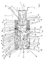
- FIG. 1 shows in horizontal section a drying area of a total provided with the reference numeral 10 paint shop for vehicle bodies 12th
- This drying area comprises an inlet lock area 14 for a drying tunnel 16, the drying tunnel 16 itself and an outlet lock area 18.
- the inlet lock area 14, the drying tunnel 16 and the outlet lock area 18 are of the Vehicle bodies 12 cycle in the direction of the arrow 20, wherein a not further explained in detail conveyor system 22 is used, which is known in the art.
- the illustrated section is preceded by a painting booth, not shown, and preparation stations, which correspond to the prior art; Downstream is a conventional cooling zone.
- an inert gas atmosphere is present in the interior of the drying tunnel 16, containing, for example, nitrogen and / or CO 2 .
- the inlet lock area 14 and the outlet lock area 18, which has a piston lock 19 the two named atmospheres are kept separated during the passage through the vehicle bodies 12 in such a way that the least possible loss of inert gases takes place.
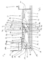
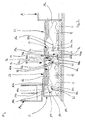
- the Piston lock 19 is in the Figures 2 . 3 and 7 shown. The operation of the lock areas 14 and 18 is not of interest here.
- the vehicle bodies 12 pass through the drying tunnel 16 in the conveying direction 20 immediately behind the inlet lock area 14 initially a top dry area 24, in which the paint outside on the roofs, the front hoods 12b and the tailgate 12a of the vehicle bodies 12 and at the substantially perpendicular to Transport direction is cured with vertical component extending surfaces in the front and rear area.
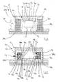
- the top drying section 24 is in the FIG. 4 shown in a vertical section transverse to the conveying direction 20 and described in more detail below.
- the top dry area 24 is followed by a side dry area 26 of the drying tunnel 16 where the paint on the outside of the vehicle and the doors 12c and 12d are cured.
- a vertical section of the side drying area 26 transversely to the conveying direction 20 shows the FIG. 5 , on the basis of which a more detailed description is given below.
- an interior dry area 28 of the drying tunnel 16 In the conveying direction 20 behind the side drying area 26 is an interior dry area 28 of the drying tunnel 16. In the interior dry area 28, the curing of the paint and the paint overspray in the interior, in the rear compartment and in the front of the vehicle bodies 12 and in an angular area of the Door, front and rear room openings. Vertical sections of the interior drying area 28 transverse to the conveying direction approximately in the middle and in the vicinity of the outlet lock area 18 are in the FIGS. 6 and 7 shown, which are used below for a more detailed description.
- the upper side drying area 24 is tapered in a region adjacent to the inlet lock area 14 in the horizontal dimension transverse to the conveying direction 20 with respect to the remaining drying tunnel 16 in order to minimize the inner volume of the drying tunnel 16 and thus the demand for inert gas ,
- a bridge portal 30 is displaceable in and against the conveying direction 20 on two parallel floor rails 32.
- the bridge portal 30 is a total of approximately U-shaped and open at the bottom (see. FIG. 4 ). It is dimensioned so that the vehicle bodies 12 can drive under it.
- the bridge portal 30 comprises, as in the FIG. 4 shown, two parallel vertical support 30b, which are interconnected at their upper ends via a horizontal cross member 30a.
- a U-shaped receiving profile 34 for five tubular UV lamps 36a is suspended on its parallel legs.
- the UV lamps 36a have a directional radiation characteristic and radiate UV light mostly towards the vehicle bodies 12.
- the paint applied in the paint booth and the paint overspray on the surfaces of the vehicle bodies 12 can be cured.
- the distance between the legs of the receiving profile 34 is greater than the maximum horizontal extent of the vehicle bodies 12 transverse to the conveying direction 20th
- the legs of the receiving profile 34 are each connected via a pivot 38 to corresponding in the Figures 2 and 3 shown longitudinal guides 39 of the vertical supports 30b of the bridge portal 30 mounted vertically displaceable.
- the vertical position of the receiving profile 34 is adaptable to the height of each of the bridge portal 30 passing portion of the vehicle body 12, for example, the front hood 12b, the roof or the tailgate 12a.
- the axes of the pivot 38 extend horizontally transversely to the conveying direction 20.
- the receiving profile 34 is pivotable about the axes of the pivot 38 motor.
- the UV radiators 36a are attached to the receiving profile 34 so that they overlap at their ends. Their axes are approximately tangent to a curve, which is aligned in its course to the outer contours of the vehicle roofs transverse to the conveying direction 20.
- the orientation of the UV lamps 36a can be optimally adjusted to the inclination of the surfaces of the bridge portal 30 passing parts with respect to the horizontal in order to always achieve a favorable illumination of the surfaces.
- the legs of the recording professionals 34 are aligned horizontally, so that the UV lamps 36a optimally stolen the approximately vertical front portion of the front hood 12b.
- the receiving profile 34 with the UV lamps 36a above the vehicle roof which extends in the middle approximately horizontally and is bent at the longitudinal edges downwards.
- the legs of the receiving profile 34 are here directed vertically downwards, so that the axes of the UV lamps 36a are largely aligned parallel to the roof surface.
- a side irradiation device 42 is provided, which in a vertical section transverse to the conveying direction 20 in FIG. 5 is shown.
- the side irradiation device 42 comprises, in the conveying direction 20 on both sides of the conveying path of the vehicle bodies 12, in each case a radiator frame 44, which carries in each case three UV radiators 36b.
- the radiator frames 44 are identical and arranged symmetrically with respect to a parallel to the conveying direction 20 extending vertical center plane on opposite sides of the conveying path of the vehicle bodies 12.
- the radiator frames 44 each have a horizontal base frame 44a, on the bottom of four rollers 44b are arranged and with which the radiator frames 44 on horizontal bottom rails 46 are transversely displaceable to the conveying direction 20.
- bottom frame 44a On the bottom frame 44a is also a further explained in more detail below filler 90b.
- Three horizontal arms 48a, 48b, 48c which extend horizontally transversely to the conveying direction 20 to the center of the drying tunnel 16, are fastened to the vertical frame 44c with each other and offset from one another.
- a cylindrical UV radiator 36b is attached in each case.
- the axes of the respective lower two UV radiators 36b extend in the vertical direction.
- the axes of the upper UV lamps 36b are inclined with their upper ends slightly towards the center of the drying tunnel 16. This is in FIG. 5 shown.
- the inclinations of the axes of the UV lamps 36b to the vertical are separately adjustable.
- Each UV emitter 36b can thus be aligned substantially parallel to the lateral surfaces of the vehicle bodies 12 in order to achieve optimum illumination.
- a tailgate opener 50 In the interior drying area 28 is adjacent to the side drying area 26 on the right in the conveying direction 20 side of the vehicle bodies 12, a tailgate opener 50. With the tailgate opener 50, the tailgate 12a of the vehicle body 12 can be opened.
- the liftgate opener 50 is constructed similar to a bonnet opener 150 which is shown in FIG FIG. 7 is shown and with which the front hood 12 b of the vehicle body 12 can be opened.
- Those elements of the bonnet opener 150, which are similar to those of the tailgate opener 50 are provided with the same reference numerals plus 100, so that the following statements apply to the tailgate opener 50 respectively for the front hood opener 150 and the FIG. 7 for understanding the following description of the tailgate opener 50 can be used.
- the tailgate opener 50 includes a handling device 52.
- a vertically oriented base body 54 of the handling device 52 is attached to the bottom of the drying tunnel 16.
- a cantilever 56 is attached, which in the horizontal direction perpendicular to the conveying direction 20 to the center of the drying tunnel 16, ie to the vehicle body 12, points out.
- a first pivot arm portion 58a of a generally three-piece pivot arm 58 is pivotally mounted about a first horizontal pivot axis at the free end of the arm 56.
- the first horizontal pivot axis is perpendicular to the conveying direction 20.
- a second, middle Schwenkarmteil 58 b is pivotally mounted at the free end of the first Schwenkarmteils 58 a about a second horizontal pivot axis which is parallel to the pivot axis 56.
- a third Schwenkarmteil 58 c is attached to the free end of the central Schwenkarmteils 58 b and extends perpendicular to this parallel to the two first horizontal pivot axes to about the middle of the drying tunnel sixteenth
- the third Schwenkarmteil 58c is mounted about its own horizontal longitudinal axis rotatably mounted on the middle Schwenkarmteil 58b.
- the third Schwenkarmteil 58c has at its free end a finger 58d which is perpendicular to the longitudinal axis of the third Schwenkarmteils 58b.
- the finger 58d may engage and / or close the tailgate 12a by correspondingly pivoting the first two pivot arm portions 58a and 58b and rotating the third pivot arm portion 58c into an opening of the tailgate 12a into which a handle or lock is mounted after painting and drying becomes. Alternatively, it can also be the opening for a resource.
- the above-mentioned bonnet opener 150 is located on the same side of the vehicle body conveyance path 12 as the tailgate opener 50. It is also located at the bottom of the drying tunnel 16 at the end of the drying tunnel 16 in the vicinity of the outlet lock area 18 when viewed in the conveying direction 20 attached.
- the terminal interior irradiation devices 60 are constructed identically and serve for irradiating the inner surfaces of the front space or the rear space with UV light.
- FIG. 1 For the sake of clarity, is in FIG. 1 only in the conveying direction 20 front interior irradiation device 60 for irradiating the frontal area, in FIG. 1 on the left, with the reference number throughout.
- the front interior irradiation device 60 is also in the FIG. 7 shown.
- Each terminal interior irradiation device 60 has a handling device 62, with a in FIG. 1 shown tubular UV radiator 36c in the front of Fron or moved into the rear compartment and can be aligned there as needed.
- the handling device 62 comprises a base body 64, which is mounted rotatably about its vertical longitudinal axis at the bottom of the drying tunnel 16.
- first elongated pivot arm portion 66a of a three-part pivot arm On the upper end side of the base body 64 is fixed one end of a first elongated pivot arm portion 66a of a three-part pivot arm, generally designated by reference numeral 66, which is particularly well-suited in the art FIG. 1 is recognizable.
- the first pivot arm part 66a extends perpendicular to the longitudinal axis of the base body 64. It is pivotable about the longitudinal axis of the base body 64 in a horizontal plane.
- the second Schwenkarmteil 66 b which extends in the horizontal direction, is pivotally mounted with one end at the other end of the first Schwenkarmteils 66 a about a second axis there in a plane perpendicular to the longitudinal axis of the base body 64, ie horizontally.
- a third Schwenkarmteils 66 c is pivotally mounted about a third axis there, which also extends parallel to the longitudinal axis of the base body 64.
- the third Schwenkarmteil 66c carries at its free end the UV lamp 36c, whose longitudinal axis is coaxial with the longitudinal axis of the third Schwenkarmteils 66c.
- the UV lamps 36c of both terminal interior Bestrahl Rheinen 60 are each aligned with the interior of the vehicle body 12 and parallel to the conveying direction 20 and extend into the front room or in the rear space in each case. In this way, optimal radiation of the respective cavities is possible.
- door openers 70 for the front doors 12c and the rear doors 12d are arranged on both sides of the conveying path for the vehicle bodies 12.
- the door openers 70 are identical.
- the two door openers 70 for the rear doors 12d are in FIG. 6 shown in vertical section.
- Each door opener 70 has a handling device 72.
- the handling device 72 comprises a base body 74, which is fixed to the bottom of the drying tunnel 16.
- a first Schwenkarmteils 76 a of a three-part pivot arm 76 is fixed and pivotable about a local there first vertical pivot axis.
- the first Schwenkarmteil 76 a extends perpendicular to the first pivot axis, ie horizontally.
- the second pivot arm portion 76b is relative to the first pivot arm portion 76a pivotally mounted about a second pivot axis.
- the second pivot axis is parallel to the first pivot axis, that is vertical.
- the second Schwenkarmteil 76b also extends horizontally.
- an elongated third Schwenkarmteil 76c is rotatably mounted about its longitudinal axis.
- the third pivot arm portion 76c extends upwardly from the second pivot arm portion 76b, parallel to the pivot axes of the first pivot arm portion 76a and the second pivot arm portion 76b, respectively.
- the third pivot arm part 76c has a finger 76d which extends substantially perpendicular to the longitudinal axis of the third pivot arm part 76c.
- the finger 76d engages to open or close the corresponding side door 12c and 12d in an opening for the subsequent door lock or a specially attached resources.
- each side two lateral interior Bestrahl Rheinbergen 80, each carrying a tubular UV emitter 36d with a cylinder radiation characteristic.
- the UV lamps 36d can, as in the FIGS. 1 and 6 shown with the doors open 12c, 12d are inserted through the door openings in the interior of the vehicle body 12 to irradiate the surfaces there.
- the sake of clarity are in the FIG. 1 the components of the lateral interior Bestrahl coupleden 80, which are located in the interior, shown in the foreground, although they are actually hidden in the local perspective by the roof or the struts of the roof of the vehicle body 12.
- the indoor irradiation devices 80 are constructed identically.
- the interior trim devices 80 associated with the rear doors 12d are shown in FIGS FIG. 6 shown in vertical section.
- the interior irradiation devices 80 each have a handling device 82, which supports and can move the UV irradiation device 36d.
- the handling device 82 has a base body 84, with which it is rotatably mounted on the ceiling of the drying tunnel 16 about a vertical first axis.
- first pivot arm portion 86a of a three-piece pivot arm Attached to the lower end of the base body 84 is an end of a first pivot arm portion 86a of a three-piece pivot arm, generally designated by reference numeral 86, which is pivotable about a horizontal second axis perpendicular to the first axis.
- a third pivot arm portion 86c is pivotally attached at one end to the other end of the second pivot arm portion 86b about a horizontal fourth pivot axis.
- the third Schwenkarmteil 86c carries at its free end the UV lamp 36d, wherein the longitudinal axis of the UV lamp 36d is coaxial with the longitudinal axis of the third Schwenkarmteils 36c, so that the radiation of UV light is not hindered and no shadows arise.
- the UV lamps 36d can be easily inserted through the open doors 12c, 12d into the interior of the vehicle body 12 and moved there as needed, similar to what happens in the paint booth with the application equipment used there for interior painting.
- the side walls of the drying tunnel 16 have in the upper-side drying area 24 and in the interior drying area 28 each one in FIG. 1 shown door 88 through which the drying tunnel 16 is accessible.
- a plurality of interchangeable packing bodies 90 are additionally placed, which fill out unused space areas of the drying tunnel 16. In this way, the internal volume of the drying tunnel 16 is kept as low as possible in order to reduce the need for inert gas.
- the shape, size and location of the unnecessary room areas depend on the type, in particular shape and size, of the vehicle body 12.
- the filler 90 can be adjusted accordingly positioned in the interior of the drying tunnel 16.
- the cuboid filling bodies 90b are placed on the radiator frames 44 (cf. FIGS. 1 and 5 ).
- a single filler plate 90d is suspended, which in the region of the suspension of the lateral interior Bestrahll coupleden 80 has corresponding recesses.
- the packing plate 90d is in the Figures 5 and 6 shown.
- cube-shaped filling bodies 90a are also stacked on the side walls of the drying tunnel 16 on the bottom on the side facing the side drying area 26.
- each chamfered packing 90c In the region of the door opener 70 and the lateral interior Bestrahl Rheinen 80 below the packing plate 90d, adjacent to this, on the side walls each chamfered packing 90c attached.
- the filler bodies 90c have the shape of cuboids bisected along a diagonal cutting plane.
- the pointed edges of the tapered packing 90c are directed downward (see. FIGS. 1 and 6 ).
- the chamfered packing 90c are specially adapted to the type of vehicle bodies 12.
- a single cuboid filling body 90e is arranged, which extends over the entire height of the drying tunnel 16 (cf. FIG. 1 ).
- the block-shaped filling body 90e is specially adapted to this position in the drying tunnel 16. It has a recess for the base body 154 of the front hood opener 150.
- a tapered filling body 90f in the form of an irregular tetrahedron is fastened in the conveying direction 20 left rear corner of the drying tunnel 16 below the ceiling of the drying tunnel 16 at the local side wall.
- the tip of the packing 90f faces downward so that the lower portion of the drying tunnel 16 remains free so as not to hinder the freedom of movement of the terminal interior space irradiation device 60 for the front space of the vehicle body 12.
- the amount of inert gas escaping from the drying tunnel 16 is kept as small as possible.
- the vehicle body 12 is moved continuously or intermittently in the conveying direction 20, wherein the height and the orientation of the receiving profile 34 for the UV lamps 36 a is adapted by the system control to the surface contour of the part of the vehicle body 12 which passes through the bridge portal 30.
- UV lamps 36a successively the top of the front hood 12b, the roof and the tailgate 12a are irradiated and cured the local paint.
- the vehicle body 12 passes through the side dry area 26.
- the paint is cured on the substantially vertical outer sides of the vehicle body 12 and the doors 12c and 12d with the UV lamps 36b.
- the position of the radiator racks 44 and the orientation of the UV emitters 36b have already been pre-programmed to the type of vehicle body 12 in advance.
- the inclination angle of the UV lamps 36b and / or the positions of the radiator frames 44 can be easily changed type-specific according to data stored in the system control.
- the vehicle body 12 From the side drying area 26, the vehicle body 12 enters the interior dry area 28 and is placed there between the front hood opener 150 and the tailgate opener 50.
- a second vehicle body 12 can already be driven into the upper-side drying area 24 of the drying tunnel 16. This is in the FIG. 1 shown.
- the front hood 12b is opened with the bonnet opener 150 and the tailgate 12a is opened with the tailgate opener 50.
- the door openers 70 With the door openers 70, the respective side doors 12c and 12d are opened.
- the terminal interior irradiation devices 60 and the lateral interior irradiation device 80 are then computer-controlled and type-specifically actuated and the corresponding UV irradiators 36c and 36d are retracted into the front space, the rear space or the interior.
- the UV lamps 36c and 36d are placed, aligned and possibly moved so that even rugged and angled surfaces are irradiated with undirected UV light and the paint applied there or the paint overspray is cured. In this case, the light emitted by the UV lamps 36d light is reflected on the surfaces of the vehicle body 12, which additionally contributes to all the cavities are uniformly emitted.
- the ultraviolet radiators 36c and 36d of the terminal indoor irradiation devices 60 and the lateral indoor irradiation devices 80 are driven out of the respective cavities.
- the interior irradiation devices 60 and 80 are placed in the drying tunnel 16 so as not to hinder the onward conveyance of the vehicle body 12.
- the tailgate 12a, the front hood 12b and the doors 12c and 12d are then closed again with the front hood opener 150, the tailgate opener 50 and the door opener 70, respectively.
- the openers 50, 150, 70 are then placed so that they are not in the way of advancing the vehicle body 12 in the way.
- the vehicle body 12 is driven in a manner not of further interest here through the outlet lock area 18 to the outside into the cooling zone.
- the piston lock 19 reduces in not interesting here Determine the amount of lost inert gas.
- the vehicle bodies 12 can also be retracted into the drying tunnel 16 without doors 12 c, 12 d, front hood 12 a and tailgate 12 a. In this case, can be dispensed with the opener 50, 70, 150.
- the handling devices 62, 82 of the interior irradiation devices 60, 80 can then also be of simpler construction. You can then instead of three-piece pivot arms also have one or two-piece pivot arms.
- the bridge gantry 30 and the receiving profile 34 in the upper side drying area 24 can also be set manually instead of automatically, for example by an industrial robot.
- handling devices 52, 62, 72 and 82 instead of the described handling devices 52, 62, 72 and 82, other automatic handling devices, such as commercial industrial robots, may be provided.
- UV lamps 36c, 36d with cylindrical radiation characteristic can also UV lamps with others mostly non-directional radiation characteristics, for example, cylinder segment, spherical, or spherical segment radiation characteristic, or combinations thereof, are used which radiate as evenly as possible in as many spatial directions.
- All packing 90 can be both closed hollow body as well as massive body.
- UV emitters and UV LEDs can be used.
Landscapes
- Engineering & Computer Science (AREA)
- Mechanical Engineering (AREA)
- General Engineering & Computer Science (AREA)
- Life Sciences & Earth Sciences (AREA)
- Microbiology (AREA)
- Drying Of Solid Materials (AREA)
- Coating Apparatus (AREA)
Applications Claiming Priority (1)
| Application Number | Priority Date | Filing Date | Title |
|---|---|---|---|
| DE200710060105 DE102007060105A1 (de) | 2007-12-13 | 2007-12-13 | Vorrichtung zum Trocknen von Gegenständen, insbesondere lackierten Fahrzeugkarosserien |
Publications (1)
| Publication Number | Publication Date |
|---|---|
| EP2071260A1 true EP2071260A1 (fr) | 2009-06-17 |
Family
ID=40451164
Family Applications (1)
| Application Number | Title | Priority Date | Filing Date |
|---|---|---|---|
| EP08019985A Withdrawn EP2071260A1 (fr) | 2007-12-13 | 2008-11-17 | Dispositif de séchage d'objets, en particulier de carrosseries de véhicules peintes |
Country Status (2)
| Country | Link |
|---|---|
| EP (1) | EP2071260A1 (fr) |
| DE (1) | DE102007060105A1 (fr) |
Cited By (9)
| Publication number | Priority date | Publication date | Assignee | Title |
|---|---|---|---|---|
| DE102009046407A1 (de) * | 2009-11-04 | 2011-05-05 | Dürr Systems GmbH | Vorrichtung zur Strahlungsbehandlung einer Beschichtung |
| US8524330B2 (en) | 2009-03-06 | 2013-09-03 | GM Global Technology Operations LLC | Method and apparatus for paint curing |
| US20140352169A1 (en) * | 2011-11-25 | 2014-12-04 | Eisenmann Ag | Device for controlling the temperature of objects |
| JP2016138668A (ja) * | 2015-01-26 | 2016-08-04 | 日産自動車株式会社 | 塗装乾燥装置及び塗装乾燥方法 |
| JP2016138670A (ja) * | 2015-01-26 | 2016-08-04 | 日産自動車株式会社 | 塗装乾燥装置及び塗装乾燥方法 |
| CN107208968A (zh) * | 2015-01-26 | 2017-09-26 | 日产自动车株式会社 | 涂装干燥装置及涂装干燥方法 |
| EP3252411A4 (fr) * | 2015-01-26 | 2017-12-06 | Nissan Motor Co., Ltd. | Dispositif de séchage de peinture et procédé de séchage de peinture |
| EP3251752A4 (fr) * | 2015-01-26 | 2017-12-06 | Nissan Motor Co., Ltd. | Dispositif de séchage de peinture et procédé de séchage de peinture |
| US10928134B2 (en) | 2016-02-17 | 2021-02-23 | Eisenmann Se | Burner unit and device for the temperature control of objects |
Citations (7)
| Publication number | Priority date | Publication date | Assignee | Title |
|---|---|---|---|---|
| EP0456829A1 (fr) * | 1989-11-28 | 1991-11-21 | Mita Industrial Co. Ltd. | Dispositif de traitement thermique et procede de sechage de pellicules minces fonctionnelles utilisant ledit dispositif |
| EP0540884A1 (fr) * | 1991-10-08 | 1993-05-12 | Herberts Gesellschaft mit beschränkter Haftung | Procédé pour la fabrication de revêtement multicouche avec l'utilisation d'une laque transparente polymérisable radicalairement ou cationiquement |
| DE19915059A1 (de) * | 1999-04-01 | 2000-10-19 | Industrieservis Ges Fuer Innov | Infrarotbestrahlung |
| WO2005011878A2 (fr) * | 2003-07-24 | 2005-02-10 | Eisenmann Maschinenbau Gmbh & Co. Kg | Dispositif de durcissement d'un revetement d'un objet, ce revetement etant constitue d'un materiau durcissant sous l'action d'un rayonnement electromagnetique, notamment d'une peinture uv ou d'une peinture a durcissement thermique |
| WO2005014182A2 (fr) * | 2003-07-24 | 2005-02-17 | Eisenmann Maschinenbau Gmbh & Co. Kg | Dispositif pour faire durcir un revetement, constitue d'un materiau durcissant par rayonnement electromagnetique, notamment d'une peinture uv ou d'une peinture a durcissement thermique, d'un objet |
| DE102004023537A1 (de) * | 2003-07-24 | 2005-03-03 | EISENMANN Maschinenbau KG (Komplementär: Eisenmann-Stiftung) | Vorrichtung zur Aushärtung einer aus einem Material, das unter elektromagnetischer Strahlung aushärtet, insbesondere aus einem UV-Lack oder aus einem thermisch aushärtenden Lack, bestehenden Beschichtung eines Gegenstandes |
| DE102004015700A1 (de) * | 2004-03-29 | 2005-11-03 | Platsch Gmbh & Co.Kg | Flächige UV-Lichtquelle |
Family Cites Families (1)
| Publication number | Priority date | Publication date | Assignee | Title |
|---|---|---|---|---|
| EP1354640A1 (fr) * | 2002-04-19 | 2003-10-22 | Dürr Systems GmbH | Procédé et appareil pour durcir un revêtement |
-
2007
- 2007-12-13 DE DE200710060105 patent/DE102007060105A1/de not_active Ceased
-
2008
- 2008-11-17 EP EP08019985A patent/EP2071260A1/fr not_active Withdrawn
Patent Citations (7)
| Publication number | Priority date | Publication date | Assignee | Title |
|---|---|---|---|---|
| EP0456829A1 (fr) * | 1989-11-28 | 1991-11-21 | Mita Industrial Co. Ltd. | Dispositif de traitement thermique et procede de sechage de pellicules minces fonctionnelles utilisant ledit dispositif |
| EP0540884A1 (fr) * | 1991-10-08 | 1993-05-12 | Herberts Gesellschaft mit beschränkter Haftung | Procédé pour la fabrication de revêtement multicouche avec l'utilisation d'une laque transparente polymérisable radicalairement ou cationiquement |
| DE19915059A1 (de) * | 1999-04-01 | 2000-10-19 | Industrieservis Ges Fuer Innov | Infrarotbestrahlung |
| WO2005011878A2 (fr) * | 2003-07-24 | 2005-02-10 | Eisenmann Maschinenbau Gmbh & Co. Kg | Dispositif de durcissement d'un revetement d'un objet, ce revetement etant constitue d'un materiau durcissant sous l'action d'un rayonnement electromagnetique, notamment d'une peinture uv ou d'une peinture a durcissement thermique |
| WO2005014182A2 (fr) * | 2003-07-24 | 2005-02-17 | Eisenmann Maschinenbau Gmbh & Co. Kg | Dispositif pour faire durcir un revetement, constitue d'un materiau durcissant par rayonnement electromagnetique, notamment d'une peinture uv ou d'une peinture a durcissement thermique, d'un objet |
| DE102004023537A1 (de) * | 2003-07-24 | 2005-03-03 | EISENMANN Maschinenbau KG (Komplementär: Eisenmann-Stiftung) | Vorrichtung zur Aushärtung einer aus einem Material, das unter elektromagnetischer Strahlung aushärtet, insbesondere aus einem UV-Lack oder aus einem thermisch aushärtenden Lack, bestehenden Beschichtung eines Gegenstandes |
| DE102004015700A1 (de) * | 2004-03-29 | 2005-11-03 | Platsch Gmbh & Co.Kg | Flächige UV-Lichtquelle |
Cited By (16)
| Publication number | Priority date | Publication date | Assignee | Title |
|---|---|---|---|---|
| US8524330B2 (en) | 2009-03-06 | 2013-09-03 | GM Global Technology Operations LLC | Method and apparatus for paint curing |
| WO2011054578A1 (fr) * | 2009-11-04 | 2011-05-12 | Dürr Systems GmbH | Dispositif pour le traitement par rayonnement d'un revêtement |
| DE102009046407A1 (de) * | 2009-11-04 | 2011-05-05 | Dürr Systems GmbH | Vorrichtung zur Strahlungsbehandlung einer Beschichtung |
| US9410741B2 (en) * | 2011-11-25 | 2016-08-09 | Eisenmann Ag | Device for controlling the temperature of objects |
| US20140352169A1 (en) * | 2011-11-25 | 2014-12-04 | Eisenmann Ag | Device for controlling the temperature of objects |
| JPWO2016120965A1 (ja) * | 2015-01-26 | 2017-11-02 | 日産自動車株式会社 | 塗装乾燥装置及び塗装乾燥方法 |
| JP2016138670A (ja) * | 2015-01-26 | 2016-08-04 | 日産自動車株式会社 | 塗装乾燥装置及び塗装乾燥方法 |
| CN107208968A (zh) * | 2015-01-26 | 2017-09-26 | 日产自动车株式会社 | 涂装干燥装置及涂装干燥方法 |
| JP2016138668A (ja) * | 2015-01-26 | 2016-08-04 | 日産自動車株式会社 | 塗装乾燥装置及び塗装乾燥方法 |
| EP3252411A4 (fr) * | 2015-01-26 | 2017-12-06 | Nissan Motor Co., Ltd. | Dispositif de séchage de peinture et procédé de séchage de peinture |
| EP3251752A4 (fr) * | 2015-01-26 | 2017-12-06 | Nissan Motor Co., Ltd. | Dispositif de séchage de peinture et procédé de séchage de peinture |
| EP3252409A4 (fr) * | 2015-01-26 | 2017-12-06 | Nissan Motor Co., Ltd. | Séchoir de revêtement et procédé de séchage de revêtement |
| US10267562B2 (en) | 2015-01-26 | 2019-04-23 | Nissan Motor Co., Ltd. | Paint baking oven and paint baking method |
| US10378819B2 (en) | 2015-01-26 | 2019-08-13 | Nissan Motor Co., Ltd. | Paint baking oven and paint baking method |
| US10443937B2 (en) | 2015-01-26 | 2019-10-15 | Nissan Motor Co., Ltd. | Paint baking oven and paint baking method |
| US10928134B2 (en) | 2016-02-17 | 2021-02-23 | Eisenmann Se | Burner unit and device for the temperature control of objects |
Also Published As
| Publication number | Publication date |
|---|---|
| DE102007060105A1 (de) | 2009-06-18 |
Similar Documents
| Publication | Publication Date | Title |
|---|---|---|
| EP2071260A1 (fr) | Dispositif de séchage d'objets, en particulier de carrosseries de véhicules peintes | |
| EP1651918B1 (fr) | Dispositif de durcissement d'un revetement d'un objet, ce revetement etant constitue d'un materiau durcissant sous l'action d'un rayonnement electromagnetique, notamment d'une peinture uv ou d'une peinture a durcissement thermique | |
| DD299263A5 (de) | Vorrichtung zur lasermarkierung auf der oberflaeche von kaese oder delikatnahrungsmitteln | |
| DE102004033640A1 (de) | Farbauftragssystem | |
| DE102004023539A1 (de) | Vorrichtung zur Aushärtung einer aus einem Material, das unter elektromagnetischer Strahlung aushärtet, insbesondere aus einem UV-Lack oder aus einem thermisch aushärtenden Lack, bestehenden Beschichtung eines Gegenstandes | |
| WO2005014182A2 (fr) | Dispositif pour faire durcir un revetement, constitue d'un materiau durcissant par rayonnement electromagnetique, notamment d'une peinture uv ou d'une peinture a durcissement thermique, d'un objet | |
| EP1749176B1 (fr) | Procede et dispositif de sechage de carrosseries de vehicules peintes | |
| EP2071261B1 (fr) | Dispositif de séchage d'objets, en particulier de carrosseries de véhicules peintes | |
| DE102015109848A1 (de) | PBLS-Anlage | |
| DE102004023537B4 (de) | Vorrichtung zur Aushärtung einer aus einem Material, das unter elektromagnetischer Strahlung aushärtet, insbesondere aus einem UV-Lack oder aus einem thermisch aushärtenden Lack, bestehenden Beschichtung eines Gegenstandes | |
| DE102004023536B4 (de) | Vorrichtung zur Aushärtung einer aus einem Material, das unter elektromagnetischer Strahlung aushärtet, insbesondere aus einem UV-Lack oder aus einem thermisch aushärtenden Lack, bestehenden Beschichtung eines Gegenstandes | |
| EP2595760B1 (fr) | Unité de traitement et installation de traitement des surfaces d'objets | |
| DE69911804T2 (de) | Vorrichtung zum beschichten von gegenständen mittels pvd | |
| EP1938033B1 (fr) | Installation et procede de durcissement par rayonnement d'un revetement de piece sous gaz protecteur | |
| EP1649229B1 (fr) | Dispositif pour faire durcir un revetement, constitue d'un materiau durcissant par rayonnement electromagnetique, notamment d'une peinture uv ou d'une peinture a durcissement thermique, d'un objet | |
| DE102004023538B4 (de) | Vorrichtung zur Aushärtung einer aus einem Material, das unter elektromagnetischer Strahlung aushärtet, insbesondere aus einem UV-Lack oder thermisch aushärtendem Lack bestehenden Beschichtung eines Gegenstandes | |
| DE102010002179A1 (de) | Schleuse zum Überführen eines Werkstücks zwischen einem Außenraum und einem Innenraum eines Werkstückbehandlungsbereichs | |
| DE102010014489B3 (de) | Transportgestell zum Fördern eines Gegenstandes durch eine Trocknungsanlage, Verfahren zum Trocknen einer Beschichtung auf einem Gegenstand und Verwendung eines Transportgestells hierzu | |
| DE102004025526B4 (de) | Vorrichtung zum Trocknen von Gegenständen, insbesondere von lackierten Fahrzeugkarosserien | |
| EP3261806B1 (fr) | Dispositif pour le traitement d'objets | |
| DE19503775C1 (de) | Verfahren zur Trocknung von Lacken mittels Infrarotstrahlern | |
| DE102004040161A1 (de) | Vorrichtung zum Beschichten, insbesondere zum Lackieren, von Gegenständen, insbesondere von Fahrzeugkarosserien | |
| DE3635525C3 (de) | Abgeschlossene Anlage vornehmlich zum Beizen und/oder zur chemischen Oberflächenbehandlung von Werkstücken | |
| DE10312381A1 (de) | Verfahren zur Trocknung einer Lackierung auf einem Objekt | |
| EP1651917B1 (fr) | Dispositif de durcissement d'un revetement d'un objet, ce revetement etant constitue d'un materiau durcissant sous l'action d'un rayonnement electromagnetique, notamment d'une peinture uv ou d'une peinture a durcissement thermique |
Legal Events
| Date | Code | Title | Description |
|---|---|---|---|
| PUAI | Public reference made under article 153(3) epc to a published international application that has entered the european phase |
Free format text: ORIGINAL CODE: 0009012 |
|
| AK | Designated contracting states |
Kind code of ref document: A1 Designated state(s): AT BE BG CH CY CZ DE DK EE ES FI FR GB GR HR HU IE IS IT LI LT LU LV MC MT NL NO PL PT RO SE SI SK TR |
|
| AX | Request for extension of the european patent |
Extension state: AL BA MK RS |
|
| AKX | Designation fees paid | ||
| 17P | Request for examination filed |
Effective date: 20090710 |
|
| RBV | Designated contracting states (corrected) |
Designated state(s): DE FR IT SE |
|
| 17Q | First examination report despatched |
Effective date: 20100311 |
|
| RAP1 | Party data changed (applicant data changed or rights of an application transferred) |
Owner name: EISENMANN AG |
|
| STAA | Information on the status of an ep patent application or granted ep patent |
Free format text: STATUS: THE APPLICATION IS DEEMED TO BE WITHDRAWN |
|
| 18D | Application deemed to be withdrawn |
Effective date: 20110510 |