EP0456862A1 - Procédé et appareil pour le filage de pièces en forme de peigne pour des cages de palier à roulement - Google Patents
Procédé et appareil pour le filage de pièces en forme de peigne pour des cages de palier à roulement Download PDFInfo
- Publication number
- EP0456862A1 EP0456862A1 EP90109326A EP90109326A EP0456862A1 EP 0456862 A1 EP0456862 A1 EP 0456862A1 EP 90109326 A EP90109326 A EP 90109326A EP 90109326 A EP90109326 A EP 90109326A EP 0456862 A1 EP0456862 A1 EP 0456862A1
- Authority
- EP
- European Patent Office
- Prior art keywords
- die
- comb
- block
- receiving opening
- webs
- Prior art date
- Legal status (The legal status is an assumption and is not a legal conclusion. Google has not performed a legal analysis and makes no representation as to the accuracy of the status listed.)
- Withdrawn
Links
Images

Classifications
-
- B—PERFORMING OPERATIONS; TRANSPORTING
- B21—MECHANICAL METAL-WORKING WITHOUT ESSENTIALLY REMOVING MATERIAL; PUNCHING METAL
- B21K—MAKING FORGED OR PRESSED METAL PRODUCTS, e.g. HORSE-SHOES, RIVETS, BOLTS OR WHEELS
- B21K1/00—Making machine elements
- B21K1/05—Making machine elements cages for bearings
-
- B—PERFORMING OPERATIONS; TRANSPORTING
- B21—MECHANICAL METAL-WORKING WITHOUT ESSENTIALLY REMOVING MATERIAL; PUNCHING METAL
- B21C—MANUFACTURE OF METAL SHEETS, WIRE, RODS, TUBES, PROFILES OR LIKE SEMI-MANUFACTURED PRODUCTS OTHERWISE THAN BY ROLLING; AUXILIARY OPERATIONS USED IN CONNECTION WITH METAL-WORKING WITHOUT ESSENTIALLY REMOVING MATERIAL
- B21C23/00—Extruding metal; Impact extrusion
- B21C23/02—Making uncoated products
- B21C23/04—Making uncoated products by direct extrusion
- B21C23/14—Making other products
-
- F—MECHANICAL ENGINEERING; LIGHTING; HEATING; WEAPONS; BLASTING
- F16—ENGINEERING ELEMENTS AND UNITS; GENERAL MEASURES FOR PRODUCING AND MAINTAINING EFFECTIVE FUNCTIONING OF MACHINES OR INSTALLATIONS; THERMAL INSULATION IN GENERAL
- F16C—SHAFTS; FLEXIBLE SHAFTS; ELEMENTS OR CRANKSHAFT MECHANISMS; ROTARY BODIES OTHER THAN GEARING ELEMENTS; BEARINGS
- F16C33/00—Parts of bearings; Special methods for making bearings or parts thereof
- F16C33/30—Parts of ball or roller bearings
- F16C33/46—Cages for rollers or needles
- F16C33/4617—Massive or moulded cages having cage pockets surrounding the rollers, e.g. machined window cages
- F16C33/4641—Massive or moulded cages having cage pockets surrounding the rollers, e.g. machined window cages comprising two annular parts joined together
- F16C33/4647—Massive or moulded cages having cage pockets surrounding the rollers, e.g. machined window cages comprising two annular parts joined together made from metal, e.g. two cast parts joined by rivets
-
- F—MECHANICAL ENGINEERING; LIGHTING; HEATING; WEAPONS; BLASTING
- F16—ENGINEERING ELEMENTS AND UNITS; GENERAL MEASURES FOR PRODUCING AND MAINTAINING EFFECTIVE FUNCTIONING OF MACHINES OR INSTALLATIONS; THERMAL INSULATION IN GENERAL
- F16C—SHAFTS; FLEXIBLE SHAFTS; ELEMENTS OR CRANKSHAFT MECHANISMS; ROTARY BODIES OTHER THAN GEARING ELEMENTS; BEARINGS
- F16C19/00—Bearings with rolling contact, for exclusively rotary movement
- F16C19/22—Bearings with rolling contact, for exclusively rotary movement with bearing rollers essentially of the same size in one or more circular rows, e.g. needle bearings
- F16C19/24—Bearings with rolling contact, for exclusively rotary movement with bearing rollers essentially of the same size in one or more circular rows, e.g. needle bearings for radial load mainly
-
- F—MECHANICAL ENGINEERING; LIGHTING; HEATING; WEAPONS; BLASTING
- F16—ENGINEERING ELEMENTS AND UNITS; GENERAL MEASURES FOR PRODUCING AND MAINTAINING EFFECTIVE FUNCTIONING OF MACHINES OR INSTALLATIONS; THERMAL INSULATION IN GENERAL
- F16C—SHAFTS; FLEXIBLE SHAFTS; ELEMENTS OR CRANKSHAFT MECHANISMS; ROTARY BODIES OTHER THAN GEARING ELEMENTS; BEARINGS
- F16C2300/00—Application independent of particular apparatuses
- F16C2300/02—General use or purpose, i.e. no use, purpose, special adaptation or modification indicated or a wide variety of uses mentioned
Definitions
- the invention relates to a method and an apparatus for extruding comb parts for roller bearing cages, which consist of a comb part and a cover plate.
- a preheated ring-shaped block is inserted into the block-receiving opening of a die and pressed, as a result of which part of the material is extruded into the tool cavities intended for the design of the webs.
- the shaped comb part is then ejected from the die.
- a method for extruding comb parts for roller bearing cages is known from Polish patent specification No. 65 617, according to which a correspondingly preheated annular block is pressed into the shaping cavity of a die by means of a stamp. The material flows through the openings, the cross section of which corresponds to the cross section of the webs. The finished product has a corresponding material addition for the final machining shaping.
- the extrusion is carried out in such a way that the heat generated by friction is equal to the heat loss to the environment and to the tools.
- the comb parts obtained must be machined, although the necessary accuracy and consistency of the dimensions is not always guaranteed.
- the comb parts produced in this way have webs which have the same cross section from start to finish.
- the comb part and the cover plate are mostly connected by rivets, which is why the free ends of the webs are machined in order to design rivet pins there. These pins are then inserted into corresponding holes in the cover plate and their free ends are formed into closing heads.
- the invention has for its object to provide a method which allows comb parts to be formed by reshaping, which have rivet pins on the web ends and are dimensionally stable.
- This object is achieved in that a block is inserted into the die, the mass of which is greater than the mass of the comb part which is to be designed, and that after the working stage of forward extrusion, the material continues to be pressed, the excess of material due to Backward extrusion is eliminated and thus the material dose necessary for designing the comb part is determined, and the material is extruded forward into openings whose cross sections are smaller than those of the webs and which are used to shape the rivet pins.
- comb pieces can be produced which are provided with rivet pins. These comb pieces have exact dimensions and do not require any machining operations. It was also found that the metal structure in the comb piece is very favorable.
- the finished bearing cages have a very high strength. They can be installed in rolling bearings that are subject to high loads and must work reliably, for example in fast railway vehicles.
- the device for performing the method according to the invention has a die, which is equipped with a ring-shaped block-receiving opening and is provided with a plurality of openings which form the webs of the comb part, a die holder being provided for this die, which is equipped with ejectors and is supported on the table of a press, the plunger of which is non-positively connected to a stamp.
- the upper part of the block-receiving opening is designed such that there is a gap between the side walls of the annular part of the stamp and the side walls of this part of the block-receiving opening, through which the excess material can be pressed out of the die backwards.
- the gap between the side walls of the upper part of the block-receiving opening and the annular part of the stamp is designed in a wedge shape.
- a comb part of a roller bearing cage shown in FIG. 1 has a side ring 1, on one end face of which webs 2 are arranged.
- the free end of each web 2 is designed in the form of a rivet pin 3.
- Holes 5 are provided in a cover plate 4 shown in FIG. 2.
- the pins 3 are pressed into the holes 5 and their ends are formed into closing heads, which is shown in FIG. 3.
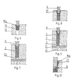
- An apparatus shown in FIG. 4 has a stamp 6 which is attached to a ram of a press, not shown in the drawing.
- the front part 6a of the stamp 6 is ring-shaped and has a rectangular cross section.
- a die holder 7 is arranged on the press table, which is not shown in the drawing, and has a cavity 8 in which an annular holder 9 for ejector 10 is installed.
- the number of ejectors 10 corresponds to the number of webs 2.
- the Holder 9 is connected to the stamp 6 by means of tie rods, not shown.
- An intermediate plate 11 is placed on the die holder 7, in which holes for the passage of the ejector 10 are provided. The diameter of these bores corresponds to the diameter of the ejector 10.
- a die 12 is supported on the intermediate plate 11, the lower part of which has mold cavities 13 for designing the rivet pins 3. Above these cavities 13 there are cavities 14 for designing the webs 2. These cavities 14 are connected to a block-receiving opening, the lower part 15b of which is rectangular and the upper part 15a of which has a trapezoidal cross section (see FIG. 4).
- the extrusion of the comb part is carried out as follows: When the punch 6 is raised and the holder 9 of the ejector 10 connected to it, a preheated annular block 16 made of brass is inserted into the lower part 15b of the block-receiving opening. The mass of the block 16 is slightly larger than the mass of the comb part which is to be designed. Then the press is started. The annular part 6a of the stamp 6 presses on the block 16, whereby the material is compressed at first (FIG. 6). Upon further pressing, the metal is extruded forward into the cavities 14, thereby forming the webs 2. When the face of the flowing material reaches the lower ends of the cavities 14, the resistance of the forming increases significantly since the material meets the smaller cross section of the cavities 13.
- the backward extrusion of the material is caused by an increase in the pressing force on the punch 6.
- the excess material flows upward through the wedge-shaped gaps between the side walls of the stamp and the side walls of the block-receiving opening and forms a ridge 17 (FIG. 8).
- the annular part 6a of the stamp closes the upwardly open annular cavity 14, the wedge-shaped gaps in the end section of the working stroke (lower reversal point of the stamp 6) having a width b of approximately 0.1 mm (see FIG. 10).
- the term "working stroke of the stamp” is understood to mean the section of its movement between the first touch of the block and the lower reversal point.
- the gap width b can also be reduced further, so that the ridge 17 is sheared off during the pressing in the die and must then also be removed there.
Landscapes
- Engineering & Computer Science (AREA)
- Mechanical Engineering (AREA)
- General Engineering & Computer Science (AREA)
- Extrusion Of Metal (AREA)
Priority Applications (1)
| Application Number | Priority Date | Filing Date | Title |
|---|---|---|---|
| EP90109326A EP0456862A1 (fr) | 1990-05-17 | 1990-05-17 | Procédé et appareil pour le filage de pièces en forme de peigne pour des cages de palier à roulement |
Applications Claiming Priority (1)
| Application Number | Priority Date | Filing Date | Title |
|---|---|---|---|
| EP90109326A EP0456862A1 (fr) | 1990-05-17 | 1990-05-17 | Procédé et appareil pour le filage de pièces en forme de peigne pour des cages de palier à roulement |
Publications (1)
| Publication Number | Publication Date |
|---|---|
| EP0456862A1 true EP0456862A1 (fr) | 1991-11-21 |
Family
ID=8203991
Family Applications (1)
| Application Number | Title | Priority Date | Filing Date |
|---|---|---|---|
| EP90109326A Withdrawn EP0456862A1 (fr) | 1990-05-17 | 1990-05-17 | Procédé et appareil pour le filage de pièces en forme de peigne pour des cages de palier à roulement |
Country Status (1)
| Country | Link |
|---|---|
| EP (1) | EP0456862A1 (fr) |
Citations (5)
| Publication number | Priority date | Publication date | Assignee | Title |
|---|---|---|---|---|
| US3150773A (en) * | 1963-01-04 | 1964-09-29 | American Metal Climax Inc | Material forming process and apparatus |
| US3314278A (en) * | 1964-03-03 | 1967-04-18 | Daniel T Bergman | Forging process and product therefrom |
| EP0117213A1 (fr) * | 1983-02-15 | 1984-08-29 | ATELIERS MECANIQUES ET INDUSTRIES SPECIALES A.M.I.S. (Société anonyme) | Outillage de formage à froid de pièces métalliques comportant des éléments axiaux opposés |
| JPS59159241A (ja) * | 1983-03-02 | 1984-09-08 | Hitachi Ltd | スクロ−ル部材の成形方法 |
| DE8702734U1 (de) * | 1987-02-23 | 1987-04-16 | Friedrich Kretz GmbH & Co KG, 7530 Pforzheim | Vorrichtung zur Herstellung von Teilen für Wärmeaustauscher |
-
1990
- 1990-05-17 EP EP90109326A patent/EP0456862A1/fr not_active Withdrawn
Patent Citations (5)
| Publication number | Priority date | Publication date | Assignee | Title |
|---|---|---|---|---|
| US3150773A (en) * | 1963-01-04 | 1964-09-29 | American Metal Climax Inc | Material forming process and apparatus |
| US3314278A (en) * | 1964-03-03 | 1967-04-18 | Daniel T Bergman | Forging process and product therefrom |
| EP0117213A1 (fr) * | 1983-02-15 | 1984-08-29 | ATELIERS MECANIQUES ET INDUSTRIES SPECIALES A.M.I.S. (Société anonyme) | Outillage de formage à froid de pièces métalliques comportant des éléments axiaux opposés |
| JPS59159241A (ja) * | 1983-03-02 | 1984-09-08 | Hitachi Ltd | スクロ−ル部材の成形方法 |
| DE8702734U1 (de) * | 1987-02-23 | 1987-04-16 | Friedrich Kretz GmbH & Co KG, 7530 Pforzheim | Vorrichtung zur Herstellung von Teilen für Wärmeaustauscher |
Non-Patent Citations (1)
| Title |
|---|
| PATENT ABSTRACTS OF JAPAN, Band 9, Nr. 11 (M-351)[1734], 18. Januar 1985; & JP-A-59 159 241 (HITACHI SEISAKUSHO) 08-09-1984 * |
Similar Documents
| Publication | Publication Date | Title |
|---|---|---|
| EP0418779B1 (fr) | Méthode pour manufacture de pièces d'oeuvre par découpage, en particulier dans un outil à contre découpage à précision | |
| DE19929163C1 (de) | Vorrichtung zum Feinschneiden von Werkstücken aus einem Blech | |
| DE4446815B4 (de) | Verfahren und Vorrichtung zum Auspressen eines Strangs aus einer Leichtmetall-Legierung | |
| DE69832426T2 (de) | Pressvorrichtung für Metallblech | |
| DE3116765C1 (de) | Werkzeug zum Herstellen von Senkloechern oder Passloechern in einem Blech auf einer Stanzmaschine | |
| DE19639677B4 (de) | Verfahren und Vorrichtung zur Herstellung des äußeren Elements eines Universalgelenks mit Kreuznuten | |
| DE2852429A1 (de) | Verfahren bei der herstellung von sinterteilen und werkzeug zur ausuebung des verfahrens | |
| DE3622053A1 (de) | Verdichtungsgeraet | |
| CH665367A5 (en) | Eliminating material burr at edges of press-cut component - by at least one corrective cutting step on step-wise moving metal strip | |
| EP0003139A1 (fr) | Procédé, produit brut et dispositif pour le forgeage d'un arbre de manivelle | |
| DE1452184A1 (de) | Verfahren und Vorrichtung zur Formung von Materialien | |
| EP0399373A1 (fr) | Procédé et dispositif de pressage d'un corps rigide de particules végétales en forme de poutre | |
| DE4134596A1 (de) | Verfahren zum hydrostatischen umformen von insbesondere ebenen flaechenhaften blechkoerpern aus kaltumformbarem metall und diesbezueglicher vorrichtung | |
| WO2015106961A1 (fr) | Procédé de production de passages dans un corps métallique par cisaillement à grande vitesse | |
| DE4318105B4 (de) | Kokille zum Stranggießen von Metall und Verfahren zur Herstellung der Kokille | |
| EP0787543A2 (fr) | Procédé d'extrusion de profilés ou analogues à partir de matériaux en barre et appareil à cet effet | |
| DE102005003933B4 (de) | Dorn zum Strangpressen von Gegenständen und Verfahren zur Herstellung eines Strangpressproduktes | |
| EP1764173A2 (fr) | Dispositif pour mouler de la poudre par pression | |
| DE10065255B4 (de) | Mehrstufenpresse | |
| DE10021881A1 (de) | Verfahren und Vorrichtung zum Herstellen von Strangpreßprofilen | |
| DD231749A1 (de) | Werkzeug zum lochen von hohlprofilen | |
| CH650705A5 (de) | Strangpresse sowie verfahren zum herstellen von profilen aus metallbolzen. | |
| DE2357309B2 (de) | Preßform zur pulvermetallurgischen Herstellung von Kontaktdüsen für Schweißmaschinen | |
| DE2156871B2 (de) | Druckstempel für Indirekt-Metallstrangpresse | |
| DE1988060U (de) | Rahmen fuer ziehpressen, schmiedepressen u. dgl. |
Legal Events
| Date | Code | Title | Description |
|---|---|---|---|
| PUAI | Public reference made under article 153(3) epc to a published international application that has entered the european phase |
Free format text: ORIGINAL CODE: 0009012 |
|
| AK | Designated contracting states |
Kind code of ref document: A1 Designated state(s): DE FR GB SE |
|
| STAA | Information on the status of an ep patent application or granted ep patent |
Free format text: STATUS: THE APPLICATION IS DEEMED TO BE WITHDRAWN |
|
| 18D | Application deemed to be withdrawn |
Effective date: 19920522 |