EP0787543A2 - Procédé d'extrusion de profilés ou analogues à partir de matériaux en barre et appareil à cet effet - Google Patents
Procédé d'extrusion de profilés ou analogues à partir de matériaux en barre et appareil à cet effet Download PDFInfo
- Publication number
- EP0787543A2 EP0787543A2 EP97810042A EP97810042A EP0787543A2 EP 0787543 A2 EP0787543 A2 EP 0787543A2 EP 97810042 A EP97810042 A EP 97810042A EP 97810042 A EP97810042 A EP 97810042A EP 0787543 A2 EP0787543 A2 EP 0787543A2
- Authority
- EP
- European Patent Office
- Prior art keywords
- section
- pressing direction
- recipient
- ingot
- cross
- Prior art date
- Legal status (The legal status is an assumption and is not a legal conclusion. Google has not performed a legal analysis and makes no representation as to the accuracy of the status listed.)
- Granted
Links
Images




Classifications
-
- B—PERFORMING OPERATIONS; TRANSPORTING
- B23—MACHINE TOOLS; METAL-WORKING NOT OTHERWISE PROVIDED FOR
- B23D—PLANING; SLOTTING; SHEARING; BROACHING; SAWING; FILING; SCRAPING; LIKE OPERATIONS FOR WORKING METAL BY REMOVING MATERIAL, NOT OTHERWISE PROVIDED FOR
- B23D23/00—Machines or devices for shearing or cutting profiled stock
-
- B—PERFORMING OPERATIONS; TRANSPORTING
- B21—MECHANICAL METAL-WORKING WITHOUT ESSENTIALLY REMOVING MATERIAL; PUNCHING METAL
- B21C—MANUFACTURE OF METAL SHEETS, WIRE, RODS, TUBES, PROFILES OR LIKE SEMI-MANUFACTURED PRODUCTS OTHERWISE THAN BY ROLLING; AUXILIARY OPERATIONS USED IN CONNECTION WITH METAL-WORKING WITHOUT ESSENTIALLY REMOVING MATERIAL
- B21C23/00—Extruding metal; Impact extrusion
- B21C23/01—Extruding metal; Impact extrusion starting from material of particular form or shape, e.g. mechanically pre-treated
-
- B—PERFORMING OPERATIONS; TRANSPORTING
- B21—MECHANICAL METAL-WORKING WITHOUT ESSENTIALLY REMOVING MATERIAL; PUNCHING METAL
- B21C—MANUFACTURE OF METAL SHEETS, WIRE, RODS, TUBES, PROFILES OR LIKE SEMI-MANUFACTURED PRODUCTS OTHERWISE THAN BY ROLLING; AUXILIARY OPERATIONS USED IN CONNECTION WITH METAL-WORKING WITHOUT ESSENTIALLY REMOVING MATERIAL
- B21C33/00—Feeding extrusion presses with metal to be extruded ; Loading the dummy block
-
- B—PERFORMING OPERATIONS; TRANSPORTING
- B21—MECHANICAL METAL-WORKING WITHOUT ESSENTIALLY REMOVING MATERIAL; PUNCHING METAL
- B21C—MANUFACTURE OF METAL SHEETS, WIRE, RODS, TUBES, PROFILES OR LIKE SEMI-MANUFACTURED PRODUCTS OTHERWISE THAN BY ROLLING; AUXILIARY OPERATIONS USED IN CONNECTION WITH METAL-WORKING WITHOUT ESSENTIALLY REMOVING MATERIAL
- B21C33/00—Feeding extrusion presses with metal to be extruded ; Loading the dummy block
- B21C33/006—Consecutive billets, e.g. billet profiles allowing air expulsion or bonding of billets
-
- B—PERFORMING OPERATIONS; TRANSPORTING
- B21—MECHANICAL METAL-WORKING WITHOUT ESSENTIALLY REMOVING MATERIAL; PUNCHING METAL
- B21C—MANUFACTURE OF METAL SHEETS, WIRE, RODS, TUBES, PROFILES OR LIKE SEMI-MANUFACTURED PRODUCTS OTHERWISE THAN BY ROLLING; AUXILIARY OPERATIONS USED IN CONNECTION WITH METAL-WORKING WITHOUT ESSENTIALLY REMOVING MATERIAL
- B21C35/00—Removing work or waste from extruding presses; Drawing-off extruded work; Cleaning dies, ducts, containers, or mandrels for metal extruding
-
- B—PERFORMING OPERATIONS; TRANSPORTING
- B21—MECHANICAL METAL-WORKING WITHOUT ESSENTIALLY REMOVING MATERIAL; PUNCHING METAL
- B21C—MANUFACTURE OF METAL SHEETS, WIRE, RODS, TUBES, PROFILES OR LIKE SEMI-MANUFACTURED PRODUCTS OTHERWISE THAN BY ROLLING; AUXILIARY OPERATIONS USED IN CONNECTION WITH METAL-WORKING WITHOUT ESSENTIALLY REMOVING MATERIAL
- B21C35/00—Removing work or waste from extruding presses; Drawing-off extruded work; Cleaning dies, ducts, containers, or mandrels for metal extruding
- B21C35/04—Cutting-off or removing waste
Definitions
- the invention relates to a method for extruding a profile or the like. Body from an ingot, which is guided in a recipient bore of a transducer and is fed to a mold cross section of a mold in the pressing direction by means of a press ram. In addition, the invention relates to a particularly suitable device.
- the material that has become ductile is a heated ingot or rolled rod section - in the metal sector, for example made of non-ferrous metals, sintered metals or steel, but in particular made of an aluminum alloy - from a stamp - or in hydrostatic extrusion by means of a liquid - by or several mold cross section / s of a molding tool crossing the pressing direction.
- the stamp moves towards the shape of the profile in the direction of the profile that emerges
- indirect or reverse extrusion the material is pressed against the direction of the stamp by a tool that is attached to the hollow stamp.
- a so-called pressing residue of the pressed ingot remains as a more or less disk-like structure between the two on the rear tool surface. This is usually removed by a shearing knife moved radially on the tool before the subsequent ingot - moved by the punch that has now moved back in the pick-up - strikes that tool surface and the actual molding process can be continued.
- Metal bars especially those made of aluminum alloys, are coated with impurities - for example lubricant residues - and with an oxide layer.
- impurities - for example lubricant residues - and with an oxide layer.
- the oxide particles on the forehead have proven to be extremely harmful to the structure of the resulting profile; the resulting zone with contaminating inclusions - depending on the profile shape and pressing speed - is relatively long and, with increasing quality requirements, forces longer and longer profile sections to be taken out of the resulting strand as waste - with all the resulting consequences of decreasing profitability and shrinking profile output . Numerous attempts to remedy these shortcomings have been unsuccessful.
- the inventor has set himself the goal of preventing the contamination areas occurring during the extrusion, in particular of aluminum alloys, at the transition between two adjacent blocks or ingots.
- this bar before entering the front bar end into the mold cross-section, this bar is first compressed and pushed out of the transducer in the pressing direction by a small cantilever dimension - for example 10 mm, after which a resulting disk-like section is sheared off and removed from that free bar end and the latter is then attached the cross section of the shape or the rear end of the resulting profile is brought.
- the removal of the ingot end should preferably take place at the same time as the usual shearing off of the pressing residue from the tool.
- the latter and the transducer are to be moved axially relatively away from one another at the end of a pressing operation; If their neighboring end faces are fixed to each other, the shearing process for the baling residue and bars can begin.
- the device according to the invention is characterized in that a shear knife is provided on the recipient's end of the receiver facing the molding tool; its shear blade or a corresponding separating element can be guided over the mouth of the recipient bore.
- a shear knife is provided on the recipient's end of the receiver facing the molding tool; its shear blade or a corresponding separating element can be guided over the mouth of the recipient bore.
- the period between the removal of the bar end on the tool side and the striking of the cut surface at the end of the resulting profile should be kept as short as possible.
- the distance between the adjacent end faces of the transducer on the one hand and mold on the other hand can be fixed; A shear knife with two shear blades is then inserted into the gap of exactly predetermined width, which at the same time removes the press residue of the processed ingot on the tool and the ingot end of the subsequent bar.
- These material disks can then be fed to a melting process and - freed from the harmful oxide particles in this operation - can be returned to production.
- the distance between the two shear blades of the shear knife is adjustable; this makes it possible to adapt it in the event of a deviation in the gap width, as found, for example, by scanning with a laser beam.
- Guides for the shear knife can advantageously be provided on the recipient's forehead - especially when an annular mouth section of a recipient's sleeve resting in the receiver protrudes from the recipient's forehead in a manner known per se.
- a further improvement is to be assigned to the gap between the molding tool and the transducer a spacer device which can be moved into the gap transversely to the pressing direction and can be reset, to which the molding tool and the transducer can be placed. This should allow for a quick and easy fixation of the pairing of the transducer / mold to one another.
- a preferred embodiment of the spacer device is provided with at least one stop plate or the like running in the pressing direction, the edges of which are arranged transversely to the pressing direction and form stops for the molding tool and the receiver.
- two stop plates should be connected by at least one yoke plate and connected to a movable linkage or the like. Drive device, with the stop plates then flanking the separating device (s).
- This spacing device is to be moved separately from the separating device and is inserted in front of it into the gap between the transducer and the molding tool, after which the transducer is moved up to the stop plate (s) until they rest on the molding tool. A mechanically and manipulatively complex locking of the transducer is no longer required.
- the width of the stop plates corresponds approximately to the width of the separating device containing the two shaving blades, i. H. the latter is, for example, 1 mm narrower than that stop plate (s) in order to have sufficient play for the shaving blades or the shearing process;
- the spacing device and separating device are to be moved independently of one another, since the latter is to be moved freely in the then stationary spacing device for shearing off.
- This independence of the separation device from the distance device also applies to another embodiment of the latter; this is designed as a - at least one end open - channel profile, the legs of which on the one hand and the channel bottom on the other form stops for the molding tool and the receiver, the legs running cross-sectionally parallel to the pressing direction and in the operating or shear position on both sides of the pressing residue; in this operating position of the arrangement of the receiver-channel profile molding tool, the - not always completely flat - pressing residue is advantageously in the interior of the profile before shearing off, so that the outer surface of the channel bottom faces the bolt or its end plate.
- a passage for a shear blade of the separating device is assigned to each of them, and both passages lie opposite one another on the longitudinal edges of the channel profile, that is to say they are directed in the same direction to one another.
- the shear blade assigned to the molding tool should preferably be longer than the shear blade close to the pickup.
- the pre-chamber upstream of the tool in the pressing direction for pressing an aluminum block with its so-called spreader expands according to the invention away from the diameter of the recipient bore towards the mold cross section in at least one plane running in the pressing direction, which is determined by an axis crossing this pressing direction.
- this prechamber its cross section tapers in the pressing direction on both sides of another axis which crosses the aforementioned. In this area, therefore, the material requirement for pressing is reduced compared to the bar supply; the excess material here is directed to the other axis.
- An extrusion press 10 for direct extrusion of profiles 12 has, according to FIG. 1, a press ram 16 on a press cylinder 14, which runs in the longitudinal axis A of a bore 19 penetrating a recipient or receiver 18.
- the diameter d of a press disk 17 on the free end face of the press ram 16 is slightly shorter than the free bore diameter d 1 , so that the press ram 16 is able to plunge into the so-called recipient bore.
- the mentioned free bore diameter d 1 is limited by the inner surface 20 of a recipient sleeve 21 inserted into the receiver 18 or its bore 19.
- the interior of this recipient sleeve 21 is referred to below as the recipient bore 22.
- the maximum distance between a die-side recipient front 23 and the press disk 17 in the rest position (not shown) of the press die 16 is dimensioned such that that the recipient bore 22 is a block or ingot indicated at 24 made of light metal, in particular made of a preheated aluminum alloy, placed in front of a loading carriage 26 and can be pushed into the recipient bore 22 by the press ram 16 in the pressing direction x.
- a die as a molding tool 32 rests near a recipient end 23 a remote from the press die 16. This is followed in the pressing direction x by a discharge channel 34 of the cross member 30, through which the profile 12 formed in a shape cross section 31 of the die 32 is removed becomes.
- a lifting device 36 for a shear knife 38 can be seen above the recipient end 23 a in FIG. 1 and is provided so as to be movable radially to a gap 40 between the pickup 18 and the molding tool 32.
- a so-called pressing rest 42 from which the pressing disk 17 has moved, is found on the end of the recipient bore 22 remote from the punch on the tool surface 33 facing it.
- the tool surface 33 remains at a distance from the recipient end 23 a thanks to an opening collar 44 formed by the protrusion of the recipient sleeve 21.
- the recipient bore 22 surrounds an annular collar 46 as a protrusion of the recipient sleeve 21.
- the free billet end approaches the press rest 42, for example a thickness a of 80 mm.
- the rear bar overhang e is a maximum of 20 mm.
- the recipient or receiver 18 is moved back - for example by more than 450 mm - until the pressing residue 42 is free (FIG. 5). If the bar 24 protrudes according to FIG. 6 with a collar length t of approximately 10 mm above the muzzle collar 44 beyond, the ingot 24 is pressed with the press ram 16; the ingot 24 should not be able to be displaced by the shear knife 38 in a subsequent shearing process to be described later.
- the pickup 18 is moved back against the pressing direction x until the rear tool surface 33 of the molding tool or the die 32 is at a distance n from the recipient face 23 a . In this position transducer 18 and die 32 are temporarily fixed.
- these protective vertical guide strips 50 are attached to the recipient's face 23 a above the mouth collar 44 as a knife deflector. Their depth corresponds to the height h of the mouth collar 44 (FIG. 5).
- the double blade cutter 38 which preferably consists of a blade plate 37 close to the molding tool 32 and a blade angle 37 a fixed to it, offers in FIG. 7.8 shear blades 39, 39 a of different lengths f, f 1 ; the shear blade 39 a intended for the pressing rest 42 of the blade plate 37 is longer than the scraper diameter 39 assigned to the pick-up 18. The latter slides along a deflector strip 50 a in FIG. 8.
- the rest 42 and the bar end face 49 remain closely adjacent to one another, so that the width i of the shear knife 38 a can be kept very small. This creates an extremely short path between the new bar end which is free of oxide layers and which has been formed by removing the end plate 48 and the end of the profile which is at the same time freed from the pressing residue 42.
- the pickup 18 is moved again to the die or the molding tool 32 - the pressing process can begin again.
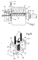
- Fig. 10 shows a double shear knife 38 of width i 1
- the lifting rod 36 passes through a rectangular yoke plate 70 with play, which in turn is fixed to a lifting rod 72 and carries a stop or spacer plate 74 of width m on both ends; the latter is slightly larger than the width i 1 of the double shear knife 38.
- This spacing device 76 comprising the yoke plate 70, the lifting rod 72 and the spacer plate 74 is lowered into the gap 40 between the sensor 18 and the die 32 in order to determine their effective distance n from one another, their being the Press direction x traversing longitudinal edges 75 stops.
- Distance device 76 and double shear knife 38 can be moved up and down separately from one another by drives, not shown.
- a channel profile 78 which is open at both ends, also serves as a positioning stop for defining that distance n or the gap width of the gap 40, which is inserted, for example, from the side.
- the channel profile 78 determines the mentioned gap width n with the cross-sectional length m of its legs 79.
- the legs 79 flank the pressing rest 42, which then stands in the profile interior or channel space 82, which is on the other hand delimited by the profile base 80.
- a flat indentation or recess 84 of a depth c of approximately 10 mm to 15 mm for the face plate 48 is formed in the profile base 80 toward the transducer 18.
- the indentation 84 is open towards the shear blade 39 so that it can be lowered onto the end plate 48 through the access 86 designed as an edge slot.
- the profile interior 82 at 88 is also equipped with an access for the - other - shear blade 39 a . Both entrances 86, 88 lie opposite one another on the upward-pointing longitudinal edges 90 of the channel profile 78.
- the die 32 according to the exemplary embodiment in FIG. 13 is preceded in the pressing direction x by a tool plate 52 of axis length b of 270 mm with a prechamber 54; in this the ductile ingot material is fed to the slit-like shape cross section 31, the horizontal longitudinal extension q of which, for example 750 mm, is considerably larger than the bore diameter d 1 of 520 mm.
- the shape cross section 31 widens on both sides to 280 mm as the longest height z 1 .
- the latter is determined in FIG. 14 by the two intersections of the longitudinal contours 31 a of the shape cross section 31 with the contour 22 a of the recipient bore 22. Outside of this, the end contour 31 e of the shape cross section 31 is part-circular.
- the lateral contour 56 of the chamber wall 58 is, according to FIG. 15, a straight line connecting the contour 22 a of the recipient bore 22, which delimits the base contour 56 b , which is curved in part-circular fashion, and the ridge contour 56 f which is curved in opposite directions 16 a funnel tapering towards the shape cross section 31.
- the three-dimensional shape of the chamber wall 58 is clear from an envelope surface 60 shown in FIG. 17.
Landscapes
- Engineering & Computer Science (AREA)
- Mechanical Engineering (AREA)
- Extrusion Of Metal (AREA)
- Extrusion Moulding Of Plastics Or The Like (AREA)
- Press-Shaping Or Shaping Using Conveyers (AREA)
- Forging (AREA)
- Shearing Machines (AREA)
- Press Drives And Press Lines (AREA)
- Pistons, Piston Rings, And Cylinders (AREA)
- Accessories And Tools For Shearing Machines (AREA)
- Formation And Processing Of Food Products (AREA)
Applications Claiming Priority (2)
| Application Number | Priority Date | Filing Date | Title |
|---|---|---|---|
| DE19603853 | 1996-02-05 | ||
| DE19603853 | 1996-02-05 |
Publications (4)
| Publication Number | Publication Date |
|---|---|
| EP0787543A2 true EP0787543A2 (fr) | 1997-08-06 |
| EP0787543A3 EP0787543A3 (fr) | 1998-06-03 |
| EP0787543B1 EP0787543B1 (fr) | 2001-12-12 |
| EP0787543B2 EP0787543B2 (fr) | 2005-02-02 |
Family
ID=7784395
Family Applications (1)
| Application Number | Title | Priority Date | Filing Date |
|---|---|---|---|
| EP97810042A Expired - Lifetime EP0787543B2 (fr) | 1996-02-05 | 1997-01-29 | Procédé d'extrusion de profilés ou analogues à partir de matériaux en barre et appareil à cet effet |
Country Status (14)
| Country | Link |
|---|---|
| US (1) | US5836190A (fr) |
| EP (1) | EP0787543B2 (fr) |
| AT (1) | ATE210514T1 (fr) |
| AU (1) | AU699911B2 (fr) |
| CA (1) | CA2196372C (fr) |
| CZ (1) | CZ291518B6 (fr) |
| DE (1) | DE19605885C1 (fr) |
| DK (1) | DK0787543T4 (fr) |
| ES (1) | ES2165011T5 (fr) |
| HU (1) | HU219838B (fr) |
| NO (1) | NO312157B1 (fr) |
| PL (1) | PL182822B1 (fr) |
| PT (1) | PT787543E (fr) |
| SK (1) | SK283676B6 (fr) |
Cited By (2)
| Publication number | Priority date | Publication date | Assignee | Title |
|---|---|---|---|---|
| EP0987068A3 (fr) * | 1998-09-16 | 2001-06-13 | Alusuisse Technology & Management AG | Procédé et dispositif d'extrusion d'un profil creux ou corps similaires à partir de matériaux en barre |
| WO2009088525A1 (fr) * | 2008-01-04 | 2009-07-16 | G. James Australia Pty. Ltd. | Procédé de soudage de segments de lopin chauffés dans un traitement d'extrusion d'aluminium |
Families Citing this family (8)
| Publication number | Priority date | Publication date | Assignee | Title |
|---|---|---|---|---|
| DE19703576C2 (de) * | 1996-02-19 | 2001-05-17 | Alusuisse Tech & Man Ag | Vorrichtung zum Strangpressen eines Profils od. dgl. Körpers aus einem Barren |
| DE19842293C2 (de) * | 1998-09-16 | 2003-06-26 | Alcan Tech & Man Ag | Verfahren zum Strangpressen eines Hohlprofils o. dgl. Körpers aus einem Barren sowie Vorrichtung dafür |
| WO2003006189A1 (fr) * | 2001-07-11 | 2003-01-23 | Alcan Technology & Management Ltd. | Dispositif pour extruder un profile ou une barre similaire a partir d'une tige ou d'un lingot |
| DE10141223C1 (de) * | 2001-07-11 | 2002-11-21 | Alusuisse Tech & Man Ag | Verfahren zum Strangpressen eines Profils od. dgl. Stranges aus einem Bolzen oder Barren sowie Vorrichtung dafür |
| DE10211267A1 (de) * | 2002-03-13 | 2003-09-25 | Sms Eumuco Gmbh | Verfahren zum Betreiben einer Metallstrangpresse, insbesondere einer liegenden Metallstrangpresse |
| KR101049629B1 (ko) * | 2006-10-16 | 2011-07-14 | 우베 고산 기카이 가부시키가이샤 | 스템 슬라이드 장치 |
| JP5468602B2 (ja) | 2009-04-20 | 2014-04-09 | 昭和電工株式会社 | 押出加工方法及び押出加工装置 |
| IT201700115300A1 (it) * | 2017-10-12 | 2019-04-12 | Davide Turla | Pressa di estrusione ad azionamento meccanico diretto. |
Family Cites Families (10)
| Publication number | Priority date | Publication date | Assignee | Title |
|---|---|---|---|---|
| DE1076064B (de) * | 1958-01-14 | 1960-02-25 | Hydraulik Gmbh | Metallstrangpresse mit Vorrichtung zum Trennen des Pressstranges vom Pressrest |
| FR1229992A (fr) * | 1959-03-27 | 1960-09-12 | Cefilac | Procédé et dispositif de coupe des produits métalliques filés à chaud |
| DE2651564C2 (de) * | 1976-11-11 | 1982-12-16 | Aluminium-Walzwerke Singen Gmbh, 7700 Singen | Vorrichtung an einer Strangpresse zum Schälen der Metallblöcke |
| FR2447758A1 (fr) * | 1979-01-31 | 1980-08-29 | Secim | Dispositif de coupe pour une presse de filage direct de billettes metalliques |
| JPS57154313A (en) * | 1981-03-20 | 1982-09-24 | Nippon Light Metal Co Ltd | Extruding method of metal |
| US4793170A (en) * | 1987-06-19 | 1988-12-27 | Everett Daniels | Shear blade for aluminum extrusion process |
| JPH04251610A (ja) * | 1991-01-24 | 1992-09-08 | Showa Alum Corp | 金属製型材の押出における材料洩れ防止方法 |
| JPH05131214A (ja) * | 1991-11-08 | 1993-05-28 | Showa Alum Corp | 押出加工装置 |
| JP2920910B2 (ja) * | 1992-03-17 | 1999-07-19 | 宇部興産株式会社 | 間接押出プレスのダイス・製品分離方法および装置 |
| JPH0671334A (ja) * | 1992-08-25 | 1994-03-15 | Ube Ind Ltd | 直接および間接兼用押出プレス |
-
1996
- 1996-02-19 DE DE19605885A patent/DE19605885C1/de not_active Expired - Fee Related
-
1997
- 1997-01-06 US US08/778,951 patent/US5836190A/en not_active Expired - Fee Related
- 1997-01-14 HU HU9700117A patent/HU219838B/hu not_active IP Right Cessation
- 1997-01-27 CZ CZ1997236A patent/CZ291518B6/cs not_active IP Right Cessation
- 1997-01-29 DK DK97810042T patent/DK0787543T4/da active
- 1997-01-29 ES ES97810042T patent/ES2165011T5/es not_active Expired - Lifetime
- 1997-01-29 PT PT97810042T patent/PT787543E/pt unknown
- 1997-01-29 AT AT97810042T patent/ATE210514T1/de not_active IP Right Cessation
- 1997-01-29 EP EP97810042A patent/EP0787543B2/fr not_active Expired - Lifetime
- 1997-01-30 AU AU12405/97A patent/AU699911B2/en not_active Ceased
- 1997-01-30 CA CA002196372A patent/CA2196372C/fr not_active Expired - Fee Related
- 1997-02-03 NO NO19970461A patent/NO312157B1/no unknown
- 1997-02-04 PL PL97318276A patent/PL182822B1/pl not_active IP Right Cessation
- 1997-02-05 SK SK163-97A patent/SK283676B6/sk unknown
Cited By (6)
| Publication number | Priority date | Publication date | Assignee | Title |
|---|---|---|---|---|
| EP0987068A3 (fr) * | 1998-09-16 | 2001-06-13 | Alusuisse Technology & Management AG | Procédé et dispositif d'extrusion d'un profil creux ou corps similaires à partir de matériaux en barre |
| WO2009088525A1 (fr) * | 2008-01-04 | 2009-07-16 | G. James Australia Pty. Ltd. | Procédé de soudage de segments de lopin chauffés dans un traitement d'extrusion d'aluminium |
| US7712651B2 (en) | 2008-01-04 | 2010-05-11 | G. James Australia Pty. Ltd. | Method of welding heated log segments in an aluminum extrusion process |
| US7950566B2 (en) | 2008-01-04 | 2011-05-31 | G. James Australia Pty. Ltd. | Method of welding heated log segments in an aluminum extrusion process |
| EP2384831A1 (fr) * | 2008-01-04 | 2011-11-09 | G. James Australia Pty. Ltd. | Méthode de soudage des segments de billettes dans une presse à filer d'aluminium |
| CN101918156B (zh) * | 2008-01-04 | 2013-08-21 | G·詹姆斯澳大利亚股份有限公司 | 在铝挤压工艺中焊接被加热的原材分段的方法 |
Also Published As
| Publication number | Publication date |
|---|---|
| HU9700117D0 (en) | 1997-02-28 |
| SK283676B6 (sk) | 2003-11-04 |
| AU699911B2 (en) | 1998-12-17 |
| CA2196372C (fr) | 2003-03-18 |
| AU1240597A (en) | 1997-08-14 |
| HUP9700117A2 (en) | 1997-08-28 |
| DE19605885C1 (de) | 1997-08-21 |
| CZ291518B6 (cs) | 2003-03-12 |
| NO970461D0 (no) | 1997-02-03 |
| HUP9700117A3 (en) | 2000-03-28 |
| EP0787543B1 (fr) | 2001-12-12 |
| ES2165011T3 (es) | 2002-03-01 |
| NO312157B1 (no) | 2002-04-02 |
| NO970461L (no) | 1997-08-06 |
| DK0787543T4 (da) | 2005-06-06 |
| EP0787543A3 (fr) | 1998-06-03 |
| ATE210514T1 (de) | 2001-12-15 |
| EP0787543B2 (fr) | 2005-02-02 |
| HU219838B (hu) | 2001-08-28 |
| PL182822B1 (pl) | 2002-03-29 |
| ES2165011T5 (es) | 2005-06-16 |
| PT787543E (pt) | 2002-05-31 |
| DK0787543T3 (da) | 2002-04-15 |
| PL318276A1 (en) | 1997-08-18 |
| CA2196372A1 (fr) | 1997-08-06 |
| US5836190A (en) | 1998-11-17 |
| CZ23697A3 (en) | 1997-12-17 |
| SK16397A3 (en) | 1997-09-10 |
Similar Documents
| Publication | Publication Date | Title |
|---|---|---|
| DE2651564A1 (de) | Vorrichtung zum pressen von werkstuecken aus einem block | |
| EP0463201A1 (fr) | Installation de coulée continue d'acier contenant un dispositif pour éliminer des bourrelets produits pendant le découpage à l'oxygène | |
| EP0787543B1 (fr) | Procédé d'extrusion de profilés ou analogues à partir de matériaux en barre et appareil à cet effet | |
| DE10141223C1 (de) | Verfahren zum Strangpressen eines Profils od. dgl. Stranges aus einem Bolzen oder Barren sowie Vorrichtung dafür | |
| DE2310983A1 (de) | Verfahren zum gesenkschmieden von einteiligen profilrollen | |
| WO1986003440A1 (fr) | Procede et dispositf pour separer des segments de tubes | |
| DE10231328B4 (de) | Strangpresse und Stangpressverfahren | |
| DE19703576C2 (de) | Vorrichtung zum Strangpressen eines Profils od. dgl. Körpers aus einem Barren | |
| EP0987068B1 (fr) | Procédé et dispositif d'extrusion d'un profil creux ou corps similaires à partir de matériaux en barre | |
| DE102018003622A1 (de) | Vorrichtung und Verfahren zum Heraustrennen eines Werkstücks | |
| DE3108337A1 (de) | Strangpressmaschine und verfahren zum betrieb einer strangpressmaschine | |
| DE202018002305U1 (de) | Vorrichtung zum Heraustrennen eines Werkstücks | |
| DE1303557B (de) | Verfahren und Vorrichtung zum Herstel len eines elektrischen Kontaktelements | |
| DE19842293C2 (de) | Verfahren zum Strangpressen eines Hohlprofils o. dgl. Körpers aus einem Barren sowie Vorrichtung dafür | |
| DE4128677A1 (de) | Liegende metallstrangpresse | |
| EP4355511B1 (fr) | Procédé et dispositif de formage pour la fabrication de pièces moulées annulaires | |
| DE3029234A1 (de) | Metallstrangpresse zum indirekten und direkten verpressen von metallen mit einer mit dem aufnehmerhalter verbundenen vorrichtung zum abtrennen des pressrestes und zum auswechseln von matrizen | |
| DE10145877C1 (de) | Verfahren zum Strangpressen eines Hohlprofils od. dgl. Körpers aus einem Barren sowie Vorrichtung dafür | |
| DE102004057677A1 (de) | Angussvorrichtung für Spritzgießwerkzeuge | |
| DE10231562A1 (de) | Verfahren zum Strangpressen eines Profils o. dgl. Stranges aus einem Bolzen oder Barren sowie Vorrichtung dafür | |
| WO2003020454A1 (fr) | Procede pour l'extrusion d'un profile creux ou d'un corps similaire a partir d'une barre, et dispositif correspondant | |
| DE668933C (de) | Verfahren und Vorrichtung zum gleichzeitigen Entlunkern, Unterteilen und Verdichten von Rohgussmetall- und Rohgussstahlbloecken mit kreuzfoermigem Querschnitt | |
| WO2003006189A1 (fr) | Dispositif pour extruder un profile ou une barre similaire a partir d'une tige ou d'un lingot | |
| DE2208470C3 (de) | Auslaufvorrichtung für eine Elektrodenpresse | |
| DE2708586A1 (de) | Verfahren zum indirekten strangpressen und vorrichtung zur durchfuehrung des verfahrens |
Legal Events
| Date | Code | Title | Description |
|---|---|---|---|
| PUAI | Public reference made under article 153(3) epc to a published international application that has entered the european phase |
Free format text: ORIGINAL CODE: 0009012 |
|
| AK | Designated contracting states |
Kind code of ref document: A2 Designated state(s): AT BE CH DK ES FI FR GB GR IE IT LI LU NL PT SE |
|
| PUAL | Search report despatched |
Free format text: ORIGINAL CODE: 0009013 |
|
| AK | Designated contracting states |
Kind code of ref document: A3 Designated state(s): AT BE CH DE DK ES FI FR GB GR IE IT LI LU MC NL PT SE |
|
| 17P | Request for examination filed |
Effective date: 19981203 |
|
| 17Q | First examination report despatched |
Effective date: 19991115 |
|
| GRAG | Despatch of communication of intention to grant |
Free format text: ORIGINAL CODE: EPIDOS AGRA |
|
| GRAG | Despatch of communication of intention to grant |
Free format text: ORIGINAL CODE: EPIDOS AGRA |
|
| GRAH | Despatch of communication of intention to grant a patent |
Free format text: ORIGINAL CODE: EPIDOS IGRA |
|
| RBV | Designated contracting states (corrected) |
Designated state(s): AT BE CH DK ES FI FR GB GR IE IT LI LU NL PT SE |
|
| GRAH | Despatch of communication of intention to grant a patent |
Free format text: ORIGINAL CODE: EPIDOS IGRA |
|
| REG | Reference to a national code |
Ref country code: DE Ref legal event code: 8566 |
|
| GRAA | (expected) grant |
Free format text: ORIGINAL CODE: 0009210 |
|
| RAP1 | Party data changed (applicant data changed or rights of an application transferred) |
Owner name: ALCAN TECHNOLOGY & MANAGEMENT AG |
|
| AK | Designated contracting states |
Kind code of ref document: B1 Designated state(s): AT BE CH DK ES FI FR GB GR IE IT LI LU NL PT SE |
|
| REF | Corresponds to: |
Ref document number: 210514 Country of ref document: AT Date of ref document: 20011215 Kind code of ref document: T |
|
| RTI1 | Title (correction) |
Free format text: METHOD FOR EXTRUDING PROFILES OR THE LIKE FROM BARS AND DEVICE THEREFORE |
|
| REG | Reference to a national code |
Ref country code: CH Ref legal event code: EP |
|
| REG | Reference to a national code |
Ref country code: GB Ref legal event code: IF02 |
|
| REG | Reference to a national code |
Ref country code: IE Ref legal event code: FG4D Free format text: GERMAN |
|
| PGFP | Annual fee paid to national office [announced via postgrant information from national office to epo] |
Ref country code: LU Payment date: 20020129 Year of fee payment: 6 |
|
| REG | Reference to a national code |
Ref country code: ES Ref legal event code: FG2A Ref document number: 2165011 Country of ref document: ES Kind code of ref document: T3 |
|
| GBT | Gb: translation of ep patent filed (gb section 77(6)(a)/1977) |
Effective date: 20020308 |
|
| REG | Reference to a national code |
Ref country code: DK Ref legal event code: T3 |
|
| ET | Fr: translation filed | ||
| REG | Reference to a national code |
Ref country code: PT Ref legal event code: SC4A Free format text: AVAILABILITY OF NATIONAL TRANSLATION Effective date: 20020307 |
|
| REG | Reference to a national code |
Ref country code: GR Ref legal event code: EP Ref document number: 20020401008 Country of ref document: GR |
|
| PLBQ | Unpublished change to opponent data |
Free format text: ORIGINAL CODE: EPIDOS OPPO |
|
| PLBI | Opposition filed |
Free format text: ORIGINAL CODE: 0009260 |
|
| PLBF | Reply of patent proprietor to notice(s) of opposition |
Free format text: ORIGINAL CODE: EPIDOS OBSO |
|
| 26 | Opposition filed |
Opponent name: CORUS ALUMINIUM PROFILTECHNIK GMBH Effective date: 20020912 |
|
| NLR1 | Nl: opposition has been filed with the epo |
Opponent name: CORUS ALUMINIUM PROFILTECHNIK GMBH |
|
| PG25 | Lapsed in a contracting state [announced via postgrant information from national office to epo] |
Ref country code: LU Free format text: LAPSE BECAUSE OF NON-PAYMENT OF DUE FEES Effective date: 20030129 |
|
| PLBF | Reply of patent proprietor to notice(s) of opposition |
Free format text: ORIGINAL CODE: EPIDOS OBSO |
|
| PUAH | Patent maintained in amended form |
Free format text: ORIGINAL CODE: 0009272 |
|
| STAA | Information on the status of an ep patent application or granted ep patent |
Free format text: STATUS: PATENT MAINTAINED AS AMENDED |
|
| 27A | Patent maintained in amended form |
Effective date: 20050202 |
|
| AK | Designated contracting states |
Kind code of ref document: B2 Designated state(s): AT BE CH DK ES FI FR GB GR IE IT LI LU NL PT SE |
|
| REG | Reference to a national code |
Ref country code: CH Ref legal event code: AEN Free format text: AUFRECHTERHALTUNG DES PATENTES IN GEAENDERTER FORM |
|
| NLR2 | Nl: decision of opposition |
Effective date: 20050202 |
|
| REG | Reference to a national code |
Ref country code: SE Ref legal event code: RPEO |
|
| GBTA | Gb: translation of amended ep patent filed (gb section 77(6)(b)/1977) | ||
| REG | Reference to a national code |
Ref country code: GR Ref legal event code: EP Ref document number: 20050401163 Country of ref document: GR |
|
| REG | Reference to a national code |
Ref country code: DK Ref legal event code: T4 |
|
| REG | Reference to a national code |
Ref country code: ES Ref legal event code: DC2A Date of ref document: 20050214 Kind code of ref document: T5 |
|
| NLR3 | Nl: receipt of modified translations in the netherlands language after an opposition procedure | ||
| ET3 | Fr: translation filed ** decision concerning opposition | ||
| PGFP | Annual fee paid to national office [announced via postgrant information from national office to epo] |
Ref country code: AT Payment date: 20070104 Year of fee payment: 11 |
|
| PGFP | Annual fee paid to national office [announced via postgrant information from national office to epo] |
Ref country code: PT Payment date: 20070108 Year of fee payment: 11 |
|
| PGFP | Annual fee paid to national office [announced via postgrant information from national office to epo] |
Ref country code: NL Payment date: 20070124 Year of fee payment: 11 |
|
| PGFP | Annual fee paid to national office [announced via postgrant information from national office to epo] |
Ref country code: GB Payment date: 20070125 Year of fee payment: 11 |
|
| PGFP | Annual fee paid to national office [announced via postgrant information from national office to epo] |
Ref country code: ES Payment date: 20070126 Year of fee payment: 11 |
|
| PGFP | Annual fee paid to national office [announced via postgrant information from national office to epo] |
Ref country code: SE Payment date: 20070129 Year of fee payment: 11 Ref country code: CH Payment date: 20070129 Year of fee payment: 11 Ref country code: IE Payment date: 20070129 Year of fee payment: 11 |
|
| PGFP | Annual fee paid to national office [announced via postgrant information from national office to epo] |
Ref country code: FI Payment date: 20070130 Year of fee payment: 11 |
|
| PGFP | Annual fee paid to national office [announced via postgrant information from national office to epo] |
Ref country code: DK Payment date: 20070131 Year of fee payment: 11 |
|
| PGFP | Annual fee paid to national office [announced via postgrant information from national office to epo] |
Ref country code: BE Payment date: 20070301 Year of fee payment: 11 |
|
| PGFP | Annual fee paid to national office [announced via postgrant information from national office to epo] |
Ref country code: IT Payment date: 20070521 Year of fee payment: 11 |
|
| PGFP | Annual fee paid to national office [announced via postgrant information from national office to epo] |
Ref country code: GR Payment date: 20070129 Year of fee payment: 11 |
|
| PGFP | Annual fee paid to national office [announced via postgrant information from national office to epo] |
Ref country code: FR Payment date: 20070117 Year of fee payment: 11 |
|
| BERE | Be: lapsed |
Owner name: *ALCAN TECHNOLOGY & MANAGEMENT A.G. Effective date: 20080131 |
|
| REG | Reference to a national code |
Ref country code: PT Ref legal event code: MM4A Free format text: LAPSE DUE TO NON-PAYMENT OF FEES Effective date: 20080729 |
|
| REG | Reference to a national code |
Ref country code: CH Ref legal event code: PL |
|
| REG | Reference to a national code |
Ref country code: DK Ref legal event code: EBP |
|
| EUG | Se: european patent has lapsed | ||
| GBPC | Gb: european patent ceased through non-payment of renewal fee |
Effective date: 20080129 |
|
| NLV4 | Nl: lapsed or anulled due to non-payment of the annual fee |
Effective date: 20080801 |
|
| REG | Reference to a national code |
Ref country code: IE Ref legal event code: MM4A |
|
| PG25 | Lapsed in a contracting state [announced via postgrant information from national office to epo] |
Ref country code: PT Free format text: LAPSE BECAUSE OF NON-PAYMENT OF DUE FEES Effective date: 20080729 Ref country code: NL Free format text: LAPSE BECAUSE OF NON-PAYMENT OF DUE FEES Effective date: 20080801 Ref country code: LI Free format text: LAPSE BECAUSE OF NON-PAYMENT OF DUE FEES Effective date: 20080131 Ref country code: FI Free format text: LAPSE BECAUSE OF NON-PAYMENT OF DUE FEES Effective date: 20080129 Ref country code: CH Free format text: LAPSE BECAUSE OF NON-PAYMENT OF DUE FEES Effective date: 20080131 |
|
| PG25 | Lapsed in a contracting state [announced via postgrant information from national office to epo] |
Ref country code: AT Free format text: LAPSE BECAUSE OF NON-PAYMENT OF DUE FEES Effective date: 20080129 |
|
| REG | Reference to a national code |
Ref country code: FR Ref legal event code: ST Effective date: 20081029 |
|
| PG25 | Lapsed in a contracting state [announced via postgrant information from national office to epo] |
Ref country code: GB Free format text: LAPSE BECAUSE OF NON-PAYMENT OF DUE FEES Effective date: 20080129 |
|
| PG25 | Lapsed in a contracting state [announced via postgrant information from national office to epo] |
Ref country code: SE Free format text: LAPSE BECAUSE OF NON-PAYMENT OF DUE FEES Effective date: 20080130 Ref country code: IE Free format text: LAPSE BECAUSE OF NON-PAYMENT OF DUE FEES Effective date: 20080129 Ref country code: DK Free format text: LAPSE BECAUSE OF NON-PAYMENT OF DUE FEES Effective date: 20080131 |
|
| PG25 | Lapsed in a contracting state [announced via postgrant information from national office to epo] |
Ref country code: BE Free format text: LAPSE BECAUSE OF NON-PAYMENT OF DUE FEES Effective date: 20080131 |
|
| REG | Reference to a national code |
Ref country code: ES Ref legal event code: FD2A Effective date: 20080130 |
|
| PG25 | Lapsed in a contracting state [announced via postgrant information from national office to epo] |
Ref country code: FR Free format text: LAPSE BECAUSE OF NON-PAYMENT OF DUE FEES Effective date: 20080131 |
|
| PG25 | Lapsed in a contracting state [announced via postgrant information from national office to epo] |
Ref country code: GR Free format text: LAPSE BECAUSE OF NON-PAYMENT OF DUE FEES Effective date: 20080804 |
|
| PG25 | Lapsed in a contracting state [announced via postgrant information from national office to epo] |
Ref country code: ES Free format text: LAPSE BECAUSE OF NON-PAYMENT OF DUE FEES Effective date: 20080130 |
|
| PG25 | Lapsed in a contracting state [announced via postgrant information from national office to epo] |
Ref country code: IT Free format text: LAPSE BECAUSE OF NON-PAYMENT OF DUE FEES Effective date: 20080129 |