EP0456958A1 - Schlammfang - Google Patents
Schlammfang Download PDFInfo
- Publication number
- EP0456958A1 EP0456958A1 EP91101045A EP91101045A EP0456958A1 EP 0456958 A1 EP0456958 A1 EP 0456958A1 EP 91101045 A EP91101045 A EP 91101045A EP 91101045 A EP91101045 A EP 91101045A EP 0456958 A1 EP0456958 A1 EP 0456958A1
- Authority
- EP
- European Patent Office
- Prior art keywords
- sludge trap
- cover plate
- shaft
- sludge
- trap according
- Prior art date
- Legal status (The legal status is an assumption and is not a legal conclusion. Google has not performed a legal analysis and makes no representation as to the accuracy of the status listed.)
- Granted
Links
- 239000010802 sludge Substances 0.000 title claims abstract description 16
- 239000002351 wastewater Substances 0.000 claims abstract description 3
- 238000009434 installation Methods 0.000 claims description 2
- 239000002352 surface water Substances 0.000 claims description 2
- 238000007789 sealing Methods 0.000 description 4
- 230000007704 transition Effects 0.000 description 1
Images
Classifications
-
- E—FIXED CONSTRUCTIONS
- E03—WATER SUPPLY; SEWERAGE
- E03F—SEWERS; CESSPOOLS
- E03F5/00—Sewerage structures
- E03F5/04—Gullies inlets, road sinks, floor drains with or without odour seals or sediment traps
- E03F5/0407—Floor drains for indoor use
- E03F5/0408—Floor drains for indoor use specially adapted for showers
-
- E—FIXED CONSTRUCTIONS
- E03—WATER SUPPLY; SEWERAGE
- E03F—SEWERS; CESSPOOLS
- E03F5/00—Sewerage structures
- E03F5/04—Gullies inlets, road sinks, floor drains with or without odour seals or sediment traps
- E03F5/0401—Gullies for use in roads or pavements
- E03F5/0405—Gullies for use in roads or pavements with an odour seal
-
- F—MECHANICAL ENGINEERING; LIGHTING; HEATING; WEAPONS; BLASTING
- F16—ENGINEERING ELEMENTS AND UNITS; GENERAL MEASURES FOR PRODUCING AND MAINTAINING EFFECTIVE FUNCTIONING OF MACHINES OR INSTALLATIONS; THERMAL INSULATION IN GENERAL
- F16L—PIPES; JOINTS OR FITTINGS FOR PIPES; SUPPORTS FOR PIPES, CABLES OR PROTECTIVE TUBING; MEANS FOR THERMAL INSULATION IN GENERAL
- F16L23/00—Flanged joints
- F16L23/04—Flanged joints the flanges being connected by members tensioned in the radial plane
-
- E—FIXED CONSTRUCTIONS
- E03—WATER SUPPLY; SEWERAGE
- E03F—SEWERS; CESSPOOLS
- E03F5/00—Sewerage structures
- E03F5/04—Gullies inlets, road sinks, floor drains with or without odour seals or sediment traps
- E03F2005/0416—Gullies inlets, road sinks, floor drains with or without odour seals or sediment traps with an odour seal
Definitions
- the task of finding a reliable seal is achieved according to the innovation in that the end flanges of the components overlapping, double conical clamping ring is used, which integrates the sealing ring between the flanges.
- One of the components to be assembled is preferably provided with a centering projection which engages in the adjacent component.
- the sealing ring which is preferably designed as a round cord ring, is placed around this centering projection and then fits between the two clamping flanges.
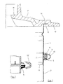
- Fig. 1 shows a section through a connection with another sealing ring 4.
- Both shaft components 1, 2 have clamping flanges 5, 6 at the ends.
- the lower end of the upper component 1 is provided with a centering projection 7, which with its inclined edge 8 in the lower component 2 engages and thus prevents the side shift.
- the round cord ring 9 is placed around the centering projection 7 and is clamped between the flanges 5, 6 by the double-conical, expandable clamping ring 10.
- the cover plate 3 which receives the cover (not shown) in the insert 11, is cantilevered to such an extent that the traffic load is guided into the ground via the projection 12 and thus the sludge collection container and the shaft components are kept largely load-free.
- an annular groove 13 is provided on the underside in which the upper flange 14 of the uppermost shaft component finds 1 place. The annular groove is so wide that the cover plate 3 is mounted securely.
- Fig. 2 shows another type of seal. It is a U-shaped sleeve 4, whose outer contour is adapted to the counter flange and the inner profile of the clamping ring 10 '.
Landscapes
- Engineering & Computer Science (AREA)
- Health & Medical Sciences (AREA)
- Life Sciences & Earth Sciences (AREA)
- Hydrology & Water Resources (AREA)
- Public Health (AREA)
- Water Supply & Treatment (AREA)
- General Engineering & Computer Science (AREA)
- Mechanical Engineering (AREA)
- Sewage (AREA)
- Treatment Of Sludge (AREA)
- Processing Of Solid Wastes (AREA)
Abstract
Description
- Die Neuerung betrifft einen befahr- oder begehbaren Schlammfang für Oberflächen- und Abwasser zum Einbau ins Erdreich. Derartige Schlammfangbehälter müssen in unterschiedlicher frostfreier oder nicht frostfreier Tiefe eingebaut werden und demzufolge mit Schaftbauteilen an die Oberfläche angepaßt werden, damit die durch einen Schachtdeckel verschließbare Abdeckplatte bündig mit der Fläche versetzt werden kann.
- Da der Schlammfanginhalt bei Aufstau nicht in das Erdreich gelangen darf, ist vorgeschrieben, die Schaftbauteile untereinander und gegen den Schlammfangbehälter abzudichten (DIN 4034).
- Die Aufgabe, eine zuverlässige Abdichtung zu finden, wird gemäß der Neuerung dadurch gelöst, daß ein die Endflansche der Bauteile übergreifender, doppelt konischer Spannring verwendet wird, der den Dichtring zwischen den Flanschen integriert. Vorzugsweise ist jeweils eines der zusammenzusetzenden Bauteile mit einem Zentrieransatz versehen, der in das benachbarte Bauteil eingreift. Der vorzugsweise als Rundschnurring ausgebildete Dichtring wird um diesen Zentrieransatz gelegt und fügt sich dann zwischen die beiden Spannflansche. Um die Verkehrslast von dem Schlammfangbehälter fernzuhalten, wird vorgeschlagen, die Abdeckplatte überkragend auszubilden. Innerhalb der Überkragung ist an ihrer Unterseite eine Nut vorgesehen, die den oberen Flansch des obersten Schaftbauteils aufnimmt. Auf diese Weise ist die Abdeckplatte verschiebesicher gelagert. Eine Abdichtung wird an dieser Stelle nicht gefordert.
- Aus der Zeichnung ist ein neuerungsgemäßer Anschluß zweier Schaftbauteile 1, 2 und die Auflagerung der Abdeckplatte 3 (Fig. 1) zu sehen. Fig. 2 zeigt einen Schnitt durch eine Verbindung mit einem anderen Dichtring 4. Beide Schaftbauteile 1, 2 besitzen an den Enden Spannflansche 5, 6. Das untere Ende des oberen Bauteils 1 ist mit einem Zentrieransatz 7 versehen, der mit seinem schrägen Rand 8 in das untere Bauteil 2 eingreift und so die Seitenverschiebung verhindert. Um den Zentrieransatz 7 ist der Rundschnurring 9 gelegt, der von dem doppelt konischen, aufweitbaren Spannring 10 zwischen den Flanschen 5, 6 eingespannt wird.
- Die Abdeckplatte 3, die in der Einlage 11 den (nicht dargestellten Deckel aufnimmt, ist so weit auskragend, daß die Verkehrslast über die Auskragung 12 in den Untergrund geleitet wird und somit der Schlammfangbehälter und die Schaftbauteile größtenteils lastfrei gehalten werden. Am Übergang zur Auskragung 12 ist an der Unterseite eine Ringnut 13 vorgesehen, in der der obere Flansch 14 des obersten Schaftbauteils 1 Platz findet. Die Ringnut ist so breit, daß die Abdeckplatte 3 verschiebesicher gelagert ist.
- Fig. 2 zeigt eine andere Dichtungsart. Es handelt sich um eine Stülpmanschette 4 in U-Form, deren Außenkontur dem Gegenflansch und dem Innenprofil des Spannrings 10' angepaßt ist.
Claims (6)
- Befahrbarer Schlammfang für Oberflächen- und Abwasser zum Einbau ins Erdreich, enthaltend einen Schlammfangbehälter, losbar und dichtend auf den Behälter aufsetzbare Schaftbauteile und eine durch einen Schachtdeckel verschließbare Abdeckplatte, dadurch gekennzeichnet, daß die Schaftbauteile (1, 2) untereinander und mit dem Behälter durch einem die Endflansche (5, 6) übergreifenden, doppelt konischen Spannring (10, 10') verbunden sind.
- Schlammfang nach Anspruch 1, dadurch gekennzeichnet, daß das jeweils obere Bauteil (1) mit einem Zentrieransatz (7, 8) versehen ist, der in das jeweils untere Bauteil (2) eingreift.
- Schlammfang nach Anspruch 2, dadurch gekennzeichnet, daß als Dichtung ein zwischen die Flansche (5, 6) und um den Zentrieransatz (7) gelegter Rundschnurring (9) verwendet wird.
- Schlammfang nach Anspruch 1 oder 2, dadurch gekennzeichnet, daß als Dichtung ein U-förmig über einen der Flansche (5) gesteckter Manschettenring (4) vorgesehen ist.
- Schlammfang nach einem der vorstehenden Ansprüche, dadurch gekennzeichnet, daß die Abdeckplatte (3) das oberste Schaftbauteil (1) außen überkragt.
- Schlammfang nach Anspruch 5, dadurch gekennzeichnet, daß die Abdeckplatte (3) innerhalb der Überkragung (12) eine Nut (13) zum Eingriff des dort mit einem Flansch (14) versehenen Schaftbauteils (1) aufweist.
Applications Claiming Priority (2)
| Application Number | Priority Date | Filing Date | Title |
|---|---|---|---|
| DE9005405U | 1990-05-12 | ||
| DE9005405U DE9005405U1 (de) | 1990-05-12 | 1990-05-12 | Schlammfang |
Publications (2)
| Publication Number | Publication Date |
|---|---|
| EP0456958A1 true EP0456958A1 (de) | 1991-11-21 |
| EP0456958B1 EP0456958B1 (de) | 1994-06-29 |
Family
ID=6853740
Family Applications (1)
| Application Number | Title | Priority Date | Filing Date |
|---|---|---|---|
| EP91101045A Expired - Lifetime EP0456958B1 (de) | 1990-05-12 | 1991-01-28 | Schlammfang |
Country Status (3)
| Country | Link |
|---|---|
| EP (1) | EP0456958B1 (de) |
| AT (1) | ATE107986T1 (de) |
| DE (2) | DE9005405U1 (de) |
Cited By (2)
| Publication number | Priority date | Publication date | Assignee | Title |
|---|---|---|---|---|
| DE4122299A1 (de) * | 1991-07-05 | 1993-01-14 | Bernhard Kessel | Schachtelement und revisionsschacht |
| EP0631019A1 (de) * | 1993-06-22 | 1994-12-28 | Bernhard Kessel | Schacht oder Behälter |
Citations (3)
| Publication number | Priority date | Publication date | Assignee | Title |
|---|---|---|---|---|
| DE819024C (de) * | 1950-01-03 | 1951-10-29 | Ver Werkstaetten Wittenau G M | Abdichtende Verbindung von Flanschen mittels Spannbandes |
| DE3620182A1 (de) * | 1986-06-14 | 1987-12-17 | Bernhard Kessel | Bodenablauf |
| EP0286562A2 (de) * | 1987-04-07 | 1988-10-12 | Pont-A-Mousson S.A. | Strassenschacht mit T-förmigem Scharnier |
-
1990
- 1990-05-12 DE DE9005405U patent/DE9005405U1/de not_active Expired - Lifetime
-
1991
- 1991-01-28 EP EP91101045A patent/EP0456958B1/de not_active Expired - Lifetime
- 1991-01-28 AT AT91101045T patent/ATE107986T1/de not_active IP Right Cessation
- 1991-01-28 DE DE59102055T patent/DE59102055D1/de not_active Expired - Fee Related
Patent Citations (3)
| Publication number | Priority date | Publication date | Assignee | Title |
|---|---|---|---|---|
| DE819024C (de) * | 1950-01-03 | 1951-10-29 | Ver Werkstaetten Wittenau G M | Abdichtende Verbindung von Flanschen mittels Spannbandes |
| DE3620182A1 (de) * | 1986-06-14 | 1987-12-17 | Bernhard Kessel | Bodenablauf |
| EP0286562A2 (de) * | 1987-04-07 | 1988-10-12 | Pont-A-Mousson S.A. | Strassenschacht mit T-förmigem Scharnier |
Cited By (3)
| Publication number | Priority date | Publication date | Assignee | Title |
|---|---|---|---|---|
| DE4122299A1 (de) * | 1991-07-05 | 1993-01-14 | Bernhard Kessel | Schachtelement und revisionsschacht |
| DE4122299C2 (de) * | 1991-07-05 | 1996-05-23 | Bernhard Kessel | Schacht |
| EP0631019A1 (de) * | 1993-06-22 | 1994-12-28 | Bernhard Kessel | Schacht oder Behälter |
Also Published As
| Publication number | Publication date |
|---|---|
| ATE107986T1 (de) | 1994-07-15 |
| DE59102055D1 (de) | 1994-08-04 |
| EP0456958B1 (de) | 1994-06-29 |
| DE9005405U1 (de) | 1990-08-02 |
Similar Documents
| Publication | Publication Date | Title |
|---|---|---|
| DE9011590U1 (de) | Kunststoffdeckel für blasgeformte Kunststoffässer | |
| DE3231186A1 (de) | Vorrichtung zum entwaessern von schlaemmen | |
| DE19649864A1 (de) | Selbsttätige Entwässerungsvorrichtung für Frachtcontainer oder andere Ladungen aufnehmende Räume | |
| EP0999311A1 (de) | Schachtdeckel zum staubdichten Verschliessen eines Schachtes, insbesondere eines Brunnenschachtes | |
| DE112019004674T5 (de) | Filterelement mit intermittierender Kupplung mit Gehäuseabdeckung | |
| EP0456958A1 (de) | Schlammfang | |
| DE10260225B4 (de) | Behälter aus Kunststoff, insbesondere Eimer | |
| DE9015918U1 (de) | Topfförmiges Gefäß, insbesondere Eimer, mit Deckel | |
| DE3322259A1 (de) | Abwasserhebeanlage | |
| DE3400059C2 (de) | Spannbandtauglicher Verschluß für Weithalsfässer aus Kunststoff mit Deckel | |
| DD296724A5 (de) | Kreisrunder schachtdeckel aus gusseisen und beton mit lueftungsoeffnungen | |
| DE29506860U1 (de) | Wasserübergabeschacht mit kunststoffhaltigen Segmenten | |
| DE3008776C2 (de) | Schachtaufsatzteil mit Verschlußdeckel | |
| DE2035854A1 (de) | Montage-Tank | |
| DE4231747C2 (de) | Tankcontainer zur Entsorgung von überwachungsbedürftigen Flüssigkeiten und Schlämmen | |
| EP0572908B1 (de) | Schachtabdeckung | |
| CH685914A5 (de) | Kochgefoss. | |
| DE6937508U (de) | Deckelverschluss mit spannband fuer behaelter aus kunststoff, insbesondere fuer faesser | |
| DE3933918C2 (de) | Spannringverschluß | |
| EP0299271A2 (de) | Container beschickungsvorrichtung für Feststoff-Entwässerungs- und Transportpressen | |
| DE8535915U1 (de) | Akkumulatorgehäuse mit einem Deckel | |
| DE3822955A1 (de) | Entwaesserungsgegenstand | |
| DE3013624A1 (de) | Gehaeuse fuer aquarienfilter | |
| DE4330553A1 (de) | Bodenablauf | |
| DE29723385U1 (de) | Druckluftanordnung |
Legal Events
| Date | Code | Title | Description |
|---|---|---|---|
| PUAI | Public reference made under article 153(3) epc to a published international application that has entered the european phase |
Free format text: ORIGINAL CODE: 0009012 |
|
| AK | Designated contracting states |
Kind code of ref document: A1 Designated state(s): AT BE DE FR NL |
|
| 17P | Request for examination filed |
Effective date: 19920402 |
|
| 17Q | First examination report despatched |
Effective date: 19921030 |
|
| GRAA | (expected) grant |
Free format text: ORIGINAL CODE: 0009210 |
|
| AK | Designated contracting states |
Kind code of ref document: B1 Designated state(s): AT BE DE FR NL |
|
| REF | Corresponds to: |
Ref document number: 107986 Country of ref document: AT Date of ref document: 19940715 Kind code of ref document: T |
|
| REF | Corresponds to: |
Ref document number: 59102055 Country of ref document: DE Date of ref document: 19940804 |
|
| ET | Fr: translation filed | ||
| PLBE | No opposition filed within time limit |
Free format text: ORIGINAL CODE: 0009261 |
|
| STAA | Information on the status of an ep patent application or granted ep patent |
Free format text: STATUS: NO OPPOSITION FILED WITHIN TIME LIMIT |
|
| 26N | No opposition filed | ||
| PGFP | Annual fee paid to national office [announced via postgrant information from national office to epo] |
Ref country code: FR Payment date: 19951030 Year of fee payment: 6 |
|
| PG25 | Lapsed in a contracting state [announced via postgrant information from national office to epo] |
Ref country code: FR Effective date: 19970930 |
|
| REG | Reference to a national code |
Ref country code: FR Ref legal event code: ST |
|
| PGFP | Annual fee paid to national office [announced via postgrant information from national office to epo] |
Ref country code: BE Payment date: 19990118 Year of fee payment: 9 |
|
| PGFP | Annual fee paid to national office [announced via postgrant information from national office to epo] |
Ref country code: NL Payment date: 19990131 Year of fee payment: 9 |
|
| PG25 | Lapsed in a contracting state [announced via postgrant information from national office to epo] |
Ref country code: BE Free format text: LAPSE BECAUSE OF NON-PAYMENT OF DUE FEES Effective date: 20000131 |
|
| BERE | Be: lapsed |
Owner name: PASSAVANT-WERKE A.G. Effective date: 20000131 |
|
| PG25 | Lapsed in a contracting state [announced via postgrant information from national office to epo] |
Ref country code: NL Free format text: LAPSE BECAUSE OF NON-PAYMENT OF DUE FEES Effective date: 20000801 |
|
| NLV4 | Nl: lapsed or anulled due to non-payment of the annual fee |
Effective date: 20000801 |
|
| PGFP | Annual fee paid to national office [announced via postgrant information from national office to epo] |
Ref country code: AT Payment date: 20030110 Year of fee payment: 13 |
|
| PG25 | Lapsed in a contracting state [announced via postgrant information from national office to epo] |
Ref country code: AT Free format text: LAPSE BECAUSE OF NON-PAYMENT OF DUE FEES Effective date: 20040128 |
|
| PGFP | Annual fee paid to national office [announced via postgrant information from national office to epo] |
Ref country code: DE Payment date: 20090326 Year of fee payment: 19 |
|
| PG25 | Lapsed in a contracting state [announced via postgrant information from national office to epo] |
Ref country code: DE Free format text: LAPSE BECAUSE OF NON-PAYMENT OF DUE FEES Effective date: 20100803 |