EP0456980B1 - Schi - Google Patents
Schi Download PDFInfo
- Publication number
- EP0456980B1 EP0456980B1 EP91103657A EP91103657A EP0456980B1 EP 0456980 B1 EP0456980 B1 EP 0456980B1 EP 91103657 A EP91103657 A EP 91103657A EP 91103657 A EP91103657 A EP 91103657A EP 0456980 B1 EP0456980 B1 EP 0456980B1
- Authority
- EP
- European Patent Office
- Prior art keywords
- ski
- tip
- tongue
- recess
- frontal face
- Prior art date
- Legal status (The legal status is an assumption and is not a legal conclusion. Google has not performed a legal analysis and makes no representation as to the accuracy of the status listed.)
- Expired - Lifetime
Links
- 230000035939 shock Effects 0.000 claims description 20
- 239000006096 absorbing agent Substances 0.000 claims description 11
- 239000013013 elastic material Substances 0.000 claims description 10
- 239000000463 material Substances 0.000 claims description 8
- 230000002093 peripheral effect Effects 0.000 claims description 4
- 230000006835 compression Effects 0.000 claims description 3
- 238000007906 compression Methods 0.000 claims description 3
- 230000014759 maintenance of location Effects 0.000 description 2
- 230000000717 retained effect Effects 0.000 description 2
- 208000027418 Wounds and injury Diseases 0.000 description 1
- 238000004026 adhesive bonding Methods 0.000 description 1
- 238000005452 bending Methods 0.000 description 1
- 230000015556 catabolic process Effects 0.000 description 1
- 238000010276 construction Methods 0.000 description 1
- 230000006378 damage Effects 0.000 description 1
- 238000013016 damping Methods 0.000 description 1
- 238000006731 degradation reaction Methods 0.000 description 1
- 230000000694 effects Effects 0.000 description 1
- 230000005489 elastic deformation Effects 0.000 description 1
- 238000002347 injection Methods 0.000 description 1
- 239000007924 injection Substances 0.000 description 1
- 208000014674 injury Diseases 0.000 description 1
- 238000012423 maintenance Methods 0.000 description 1
- 238000007789 sealing Methods 0.000 description 1
- 239000011359 shock absorbing material Substances 0.000 description 1
- 239000007787 solid Substances 0.000 description 1
Images


Classifications
-
- A—HUMAN NECESSITIES
- A63—SPORTS; GAMES; AMUSEMENTS
- A63C—SKATES; SKIS; ROLLER SKATES; DESIGN OR LAYOUT OF COURTS, RINKS OR THE LIKE
- A63C5/00—Skis or snowboards
- A63C5/06—Skis or snowboards with special devices thereon, e.g. steering devices
- A63C5/062—Protection or reinforcement devices for the ski-tip or the ski rear end
-
- A—HUMAN NECESSITIES
- A63—SPORTS; GAMES; AMUSEMENTS
- A63C—SKATES; SKIS; ROLLER SKATES; DESIGN OR LAYOUT OF COURTS, RINKS OR THE LIKE
- A63C5/00—Skis or snowboards
- A63C5/04—Structure of the surface thereof
- A63C5/052—Structure of the surface thereof of the tips or rear ends
Definitions
- the present invention relates to a ski and more particularly to an improvement of its front end.
- Alpine, cross-country or cross-country skiing ends at the front with a spatula which is curved upwards so as to facilitate sliding of the ski over snow.
- This tip which generally ends in a point, is an integral part of the rest of the ski and therefore it can cause serious injury to another skier, in the event of a frontal impact with the latter.
- a rigid spatula forming a single piece with the rest of the ski, can destabilize the skier or even cause his fall if it comes to strike a stake when the skier makes a descent marked by such stakes (slalom test for example ).
- the frontal shocks received by the tip are transmitted to the entire ski and this may result in degradation of the latter.
- Document EP-A2-0229608 describes an invention relating to a ski, the tip of which is produced in the form of an attached elastic element; the plastic material constituting the element being chosen to allow to adapt the elasticity and / or the stiffness of the spatula.
- the present invention aims to remedy these various drawbacks.
- this ski comprising, at the front, a spatula, is characterized in that its spatula is constituted by a part independent of the ski itself, mounted movable relative to the front of the ski, and by at least one element. elastic interposed between the independent moving part and the front of the ski itself.
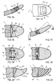
- Figure 1 is a vertical and longitudinal sectional view of the front part of a ski having an independent spatula which can slide longitudinally.
- FIG. 2 is a substantially horizontal sectional view taken along line II-II of FIG. 1.
- Figure 3 is a cross-sectional view taken along line III-III of Figure 1.
- FIG. 4 is a plan view of the front part of the ski shown in FIG. 1.
- Figures 5 and 6 are views in vertical and longitudinal section of alternative embodiments of the front part of the ski.
- Figure 7 is a plan view of another alternative embodiment of the front part of the ski.
- FIG. 8 is a view in vertical and longitudinal section of the front part of the ski shown in FIG. 7.
- Figure 9 is a vertical and longitudinal sectional view of another alternative embodiment of the front part of the ski.
- FIG. 10 is a substantially horizontal sectional view taken along the line X-X in FIG. 9.
- FIG. 11 is a plan view of the front part of the ski shown in FIG. 9.
- Figure 12 is a vertical and longitudinal sectional view of another alternative embodiment of the front part of a ski.
- FIG. 13 is a substantially horizontal sectional view taken along line XIII-XIII of FIG. 12.
- Figure 14 is a vertical and longitudinal sectional view of another alternative embodiment of the front part of a ski.
- FIG. 15 is a plan view of the front part of the ski shown in FIG. 16.
- Figures 16 and 17 are views in substantially horizontal section of alternative embodiments of the front part of the ski.
- Figure 18 is a vertical and longitudinal sectional view of an alternative embodiment of the front part of a spatula ski that can pivot about a transverse axis.
- FIG. 19 is a substantially horizontal sectional view taken along the line XXI-XXI of FIG. 20.
- Figures 20 and 21 are plan views of the front part of skis having an independent asymmetrical tip.
- the tip comprises an independent tip 2 which is mounted to slide longitudinally on the front of the ski 1.
- the tip 2 is hollowed out by a blind recess 3 extending in the plane of the 'tip 2, closed at the front by a transverse bottom 3a and which opens into the posterior front face 2a of the cap 2.
- a central tongue 4 which is an integral part of the ski 1 and which s' extends forward from the front face 1a of the ski 1 proper.
- This tongue 4 has a width or transverse dimension less than the width of the ski and its thickness is substantially equal to the vertical dimension of the recess 3 so that the end piece 2 is fitted tightly onto the tongue 4, while being able to slide on this tab.
- the front front face 4a of the tongue is located at a distance behind the bottom 3a of the recess 3 so as to leave a longitudinal play a between them allowing a slight sliding of the end piece 2 towards the rear.
- the ski tip also has an elastic element 5, forming a shock absorber, which is interposed between the rear front face 2a of the end piece 2 and the front front face 1a of the ski 1.
- the shock absorbing element 5 can be formed , as shown in the embodiment illustrated in Figures 1 to 4, by a ring of an elastic material, for example of the rubber type, which is integral with the rear end face 2a of the nozzle 2, surrounding the opening of the recess 3 into which the tongue 4 enters.
- the elastic ring 5 can be fixed to the rear front face 2a of the end piece 2 by any appropriate means, for example by overmolding or by bi-material injection.
- the end piece 2 is itself made of a relatively hard material allowing it to absorb shocks and wear.
- the tip 2 of the tip can, in the event of a frontal impact, slide backwards with respect to the ski 1, compressing the elastic element 5 forming a shock absorber.
- This sliding movement is made possible by the longitudinal play a existing between the front front face 4a of the central tongue 4 and the front transverse bottom 3a of the recess 3.
- the tip 2 of the spatula is retained forward, on the central tongue 4, by any appropriate means.
- this retention can be ensured by providing, in the two lateral faces of the tongue 4, two opposite notches 6, formed at the place where the tongue 4 is connected to the front front face 1a of the ski 1.
- the ring 5 forming shock absorber, secured to the tip 2 of the spatula is engaged elastically in the two opposite notches 6, which ensures, because the ring 5 is secured to the tip 2, the maintenance in place of this tip on the tongue 4, by "snap", in the extension of the front of the ski 1.
- the parts of the elastic ring which are engaged in the two notches 6, have convex surfaces closely matching the concave profiles of the two notches 6.
- similar notches can also be provided in the upper and lower faces of the tongue 4 so that the elastic ring 5 is anchored on the four faces of the tongue 4.
- the recess 3 and the tongue 4 may each have a rectangular shape or, which is preferable, an isosceles trapezoid shape converging towards the front, as can best be seen in FIGS. 2 and 4.
- the part of the trapezoidal tongue 4 which is engaged in the recess 3, has a longitudinal dimension which is less than the depth or longitudinal dimension of the trapezoidal recess 3.
- the inclined lateral faces 4b of the trapezoidal tongue 4 have a angle of inclination between them which is greater than the angle of inclination of the two inclined lateral faces 3b of the trapezoidal recess 3.
- the longitudinal play a and the lateral play b thus allow the end piece 2 to undergo, in the event of an impact, not only a pure longitudinal movement towards the rear, in the event of a purely frontal impact, but also a complex movement of translation towards the rear and lateral pivoting, in the event of an oblique impact, this lateral pivoting being made possible as a result of the provision for lateral clearance b .
- the overall thickness of the elastic ring 5 forming a shock absorber which is equal to that of the end piece 2, in the region of its posterior front face 2a, is slightly greater than the thickness of the front of the ski 1, so that the upper and lower faces of the elastic ring 5 are slightly projecting from the upper and lower faces of the ski 1.
- the elastic ring 5 is extended towards the rear by an external peripheral lip 5a which covers, over a short distance, the upper and lower faces of the ski 1, thus ensuring continuity between the ski 1 and the elastic ring 5.
- a layer of elastic material 5b is also interposed between the upper and lower faces of the central tongue 4 and the upper and lower faces of the recess 3, in order also to create a damping of the shocks in the vertical direction.
- the central tongue 4 and the recess 3 are removed and the elastic element 5 shock absorber is then constituted by a piece of solid elastic material, extending transversely and ensuring the junction between the rear end face 2a full of the mouthpiece 2 of the tip and the front face 1a of the ski 1.
- the elastic member 5 is fixed by any suitable means, for example by gluing, to the two end faces 1a and 2a.
- the elastic element forming a shock absorber consists of a mass of elastic material 7 which fills the space delimited between the faces 3a, 3b of the recess 3 and 4a, 4b of the tongue 4.
- the retention of the endpiece 2 towards the front is obtained by bosses 8 which are formed in the zone of connection of the lateral faces 3b of the recess 3 and of the posterior front face 2a end piece 2 and which project inwards. These bosses 8 are engaged respectively in the two notches 6 provided in the lateral faces of the central tongue 4.
- the rear front face 2a of the end piece 2 defines, with the front front face 1a of the ski 1, an empty space 9 which is surrounded by a peripheral sealing lip 11, extending towards the rear, making integral part of the end piece 2.
- This lip 11 covers the four faces of the ski 1 over which it can slide.
- a frontal and / or lateral impact is absorbed by the elastic deformation of the layer of shock absorbing material 7 which is then compressed between the end piece 2 and the central tongue 4.
- the tip 2 is full and its front face 2a is extended rearward by a central tongue 4.
- the front part of the ski 1 is hollowed out by a recess 3 receiving the tongue 4 secured to the end piece 2.
- Figures 14 and 15 illustrate an alternative embodiment in which the central tongue 4 carries an upper plate 14, of elastic material, which is housed in a recess 15 formed in the upper part of the nozzle 2 constituting the spatula.
- the plate 14 is fixed, at its lower part, to the tongue 4 by any appropriate means, for example by lower pins passing through holes drilled in the tongue 4 and terminated by deformed heads 16 in the form of rivet heads.
- the plate 14 rests, by its tapered front part, on a ramp 17 inclined from bottom to top towards the front, which is formed on the upper face of the tip 2.
- this endpiece 2 causes, by moving back slightly with respect to the tongue 4, the lifting of the tapered front part of the plate 14, which then takes a curved shape towards the top, as indicated in dashes in FIG. 16.
- This deformation of the plate 14 makes it possible to absorb the impact energy and this plate then returns to its initial shape, due to its elasticity.
- Figures 16 and 17 illustrate alternative embodiments in which the elastic element forming shock absorber is constituted by a mechanical spring.
- the tip 2 is pushed forward by a leaf spring 18, forming a bending spring.
- This leaf spring 18 is arched so as to have a convex shape towards the front, to extend transversely and to bear, by its two ends, on the front front face 1a of the ski 1 and, by its convex median part. towards the front, against the posterior front face 2a of the end piece 2. Consequently, if the end piece 2 of the tip moves back under the effect of a frontal impact, it causes a crushing of the spring leaf 18 which thus receives the energy of the shock.
- the end piece 2 can be retained forwards by any appropriate means, for example by means of a vertical finger 19 secured to the tongue 4 and engaged in a longitudinal slot 21 in the end piece 2.
- the elastic element forming shock absorber can be constituted by at least one longitudinal compression spring.
- the tip 2 of the spatula is thus pushed forward by two compression springs 22 extending longitudinally and engaged, at their ends, in housings hollowed out opposite 'from each other respectively in the front front face 1a of the ski 1 and in the rear front face 2a of the tip 2 of the tip.
- Figures 18 and 19 illustrate an alternative embodiment in which the tip comprises an independent tip 23 which is articulated on the front of the ski 1, around a transverse axis 24.
- the tip 23 of the tip is biased towards its normal position, in the extension of the front of the ski 1, by one or more springs such as torsion springs 25.
- the energy of a frontal impact is absorbed by pivoting the end piece 23 of the spatula anticlockwise around the axis 24, the spring or springs 25 then playing the role of elastic shock absorbing element.
- the springs 25 ensure the return of the tip 23 of the tip in its normal position, in the extension of the ski 1, after the impact.
- FIG. 20 shows the front of a ski, the tip of which has a tip made of a rigid material 26 of asymmetrical shape, in the case of a ski more particularly suited to the practice of slalom.
- the endpiece 26 is connected to the front front face 1a of the ski 1 by means of an elastic element 27 which, when viewed in plan, has substantially the shape of a wedge or a sector of a circle.
- the apex 27a of the wedge-shaped elastic element 27 is situated in the plane of the outer edge 1b of the ski 1 and to this apex 27a is connected the convex outer edge 26a of the end piece 26.
- the elastic element 27 has, on the side opposite its top 27a, an edge 27b which ensures continuity between the internal edge 1c of the ski 1 and the concave internal edge 26b of the endpiece 26.
- the tip 26 of asymmetrical shape is made of elastic material and it is connected to the front end face 1a of the ski 1.
- This tip 26 has, on the side of the internal edge 1c of the ski 1, a concave edge 26b and on its convex outer edge is attached a curved element 28, made of hard impact-resistant material, which extends from the end of the nozzle 26, to the point of connection between the front wall anterior 1a of the ski 1 and its outer edge 1b.
Landscapes
- Lubricants (AREA)
- Transition And Organic Metals Composition Catalysts For Addition Polymerization (AREA)
- Polyesters Or Polycarbonates (AREA)
- Footwear And Its Accessory, Manufacturing Method And Apparatuses (AREA)
- Vibration Dampers (AREA)
- Toys (AREA)
Claims (20)
- Ski, der vorne eine Spatel aufweist, dadurch gekennzeichnet, daß diese Spatel durch ein von dem eigentlichen Ski (1) unabhängiges Teil (2, 23), das beweglich bezüglich des Vorderteiles des Ski (1) montiert ist, und durch zumindest ein elastisches Element (5, 7, 13, 14, 18, 22, 25) gebildet ist, das zwischen dem beweglichen unabhängigen Teil (2, 23) und dem Vorderteil des eigentlichen Ski (1) zwischengelegt ist.
- Ski gemäß Anspruch 1, dadurch gekennzeichnet, daß das unabhängige Teil (2) der Spatel durch einen Ansatz gebildet ist, der longitudinal gleitbar auf dem Vorderteil des Ski (1) montiert ist.
- Ski gemäß Anspruch 2, dadurch gekennzeichnet, daß der Ansatz (2), bzw. der Ski (1), durch eine blinde Ausnehmung (3) ausgehöhlt ist, die einen Boden (3a) aufweist, und die in der hinteren Stirnseite (2a) des Ansatzes 2 mündet, bzw. in der vorderen Stirnseite (1a) des Ski (1), und daß in dieser Ausnehmung (3) eine zentrale Zunge (4) eingreift, die integraler Teil des Ski (1) ist, bzw. des Ansatzes (2), und die sich ausgehend von der vorderen Stirnseite (1a) des eigentlichen Ski (1), bzw. der hinteren Stirnseite (2a) des Ansatzes (2), erstreckt.
- Ski gemäß Anspruch 3, dadurch gekennzeichnet, daß die Zunge (4) eine Breite oder ein transversales Ausmaß hat, das kleiner als die Breite des Ski ist, und daß seine Dicke im wesentlichen gleich zu dem vertikalen Ausmaß der Ausnehmung (3) ist, so daß die Zunge (4) eng in der Ausnehmung (3) eingesetzt ist.
- Ski gemäß Anspruch 4, dadurch gekennzeichnet, daß die Stirnseite (4a) der Zunge (4) im Abstand zu dem Boden (3a) der Ausnehmung (3) angeordnet ist, um so ein longitudinales Spiel (a) zwischen ihnen zu lassen.
- Ski gemäß einem der Ansprüche 3 - 5, dadurch gekennzeichnet, daß, in der Ebene gesehen, die Ausnehmung (3) und die Zunge (4) jeweils eine Form eines gleichschenkligen Trapezes haben, und daß die lateralen geneigten Seiten (4b) der trapezförmigen Zunge (4) einen Neigungswinkel zwischen sich aufweisen, der größer als der relative Neigungswinkel der beiden lateralen geneigten Seiten (3b) der trapezförmigen Ausnehmung (3) ist.
- Ski gemäß einem der Ansprüche 3 - 5, dadurch gekennzeichnet, daß der Ansatz (2) aus einem harten Material hergestellt ist, das Stößen und der Abnutzung widersteht, und daß das Stoßdämpferelement (5) durch einen Ring aus einem elastischen Material gebildet ist, z.B. einer Art Gummi, der die Öffnung der Ausnehmung (3) umgibt, in die die Zunge (4) eindringt.
- Ski gemäß Anspruch 7, dadurch gekennzeichnet, daß die Zunge (4) in ihren beiden lateralen Seiten zwei einander gegenüberliegende Kerben (6) aufweist, die an dem Ort gebildet sind, wo die Zunge (4) sich mit der vorderen Stirnseite (1a) des Ski (1) verbindet, bzw. mit der hinteren Stirnseite (2a) des Ansatzes (2), und daß der elastische Ring (5) in die beiden sich einander gegenüberliegenden Kerben (6) der Zunge (4) eingreift.
- Ski gemäß einem der Ansprüche 7 und 8, dadurch gekennzeichnet, daß der elastische Ring (5) nach hinten durch eine periphere äußere Lippe (5a) verlängert ist, die über einen geringen Abstand die Seiten des Ski (1) überdeckt.
- Ski gemäß einem der Ansprüche 3 - 5, dadurch gekennzeichnet, daß das elastische Element, das den Stoßdämpfer bildet, durch eine Masse (7) aus elastischem Material gebildet ist, die den Raum ausfüllt, der zwischen den Seiten (3a, 3b) der Ausnehmung (3) und den Seiten (4a, 4b) der Zunge (4) begrenzt ist.
- Ski gemäß Anspruch 10, dadurch gekennzeichnet, daß Buckel (8) in dem Verbindungsbereich der lateralen Seiten (3b) der Ausnehmung (3) und der hinteren Stirnseite (2a) des Ansatzes (2) gebildet sind, und daß sie nach innen vorspringen, und daß diese Buckel (8) jeweils in zwei Kerben (6) eingreifen, die in den lateralen Seiten der zentralen Zunge (4) vorgesehen sind.
- Ski gemäß einem der Ansprüche 10 und 11, dadurch gekennzeichnet, daß die hintere Stirnseite (2a) des Ansatzes (2) mit der vorderen Stirnseite (1a) des Ski (1) einen leeren Raum (9) begrenzt, der von einer peripheren Lippe (11) umgeben ist, die sich nach hinten erstreckt, wobei sie integraler Teil des Ansatzes (2) ist; und die die Seiten des Ski (1) überdeckt, auf denen sie gleiten kann.
- Ski gemäß einem der Ansprüche 3 - 5, dadurch gekennzeichnet, daß die zentrale Zunge (4) ein oberes Plättchen (14) aus elastischem Material trägt, das in einer Ausnehmung (15) aufgenommen ist, die in dem oberen Teil des Ansatzes (2) gebildet ist, daß das Plättchen (14) mit seinem unteren Teil an der Zunge (4) befestigt ist, und daß es durch seinen vorderen sich verjüngenden Teil auf einer Rampe (17) ruht, die von unten nach oben nach vorne geneigt ist, und die auf der oberen Seite des Ansatzes (2) gebildet ist.
- Ski gemäß einem der Ansprüche 3 - 5 dadurch gekennzeichnet, daß das elastische Element, das den Stoßdämpfer bildet, aus einer mechanischen Feder (18, 22) gebildet ist.
- Ski gemäß Anspruch 14, dadurch gekennzeichnet, daß die Feder (18) aus einem Durchbiegeblatt gebildet ist, das so gewölbt ist, daß es eine nach vorne konvexe Form hat, um sich transversal zu erstrecken und sich mit beiden Enden auf der vorderen Stirnseite (1a) des Ski (1), und durch seinen mittleren nach vorne konvexen Teil gegen die hintere Stirnseite (2a) des Ansatzes (2) abzustützen.
- Ski gemäß Anspruch 15, dadurch gekennzeichnet, daß das elastische Element, das den Stoßdämpfer bildet, aus zumindest einer longitudinalen Kompressionsfeder (22) gebildet ist.
- Ski gemäß Anspruch 1, dadurch gekennzeichnet, daß der unabhängige Teil (23) der Spatel aus einem Ansatz gebildet ist, der auf dem Vorderteil des Ski (1) um eine transversale Achse (24) angelenkt ist, wobei er durch ein elastisches Rückholelement (25) belastet ist.
- Ski gemäß Anspruch 1, dadurch gekennzeichnet, daß der unabhängige Teil (26) der Spatel durch einen Ansatz gebildet ist, der eine disymmetrische Form hat.
- Ski gemäß Anspruch 18, dadurch gekennzeichnet, daß der disym metrische Ansatz (26) aus steifem Material mit der vorderen Stirnseite (1a) des Ski (1) durch ein elastisches Element (27) verbunden ist, das im wesentlichen, in der Ebene gesehen, eine Form eines Keiles oder eines Kreissektors hat.
- Ski gemäß Anspruch 18, dadurch gekennzeichnet, daß der disymmetrische Ansatz (26) aus elastischem Material mit der vorderen Stirnseite (1a) des Ski (1) verbunden ist, und daß er auf seinem konvexen Rand, der sich mit der äußeren Kante (1b) des Ski (1) verbindet, ein gebogenes zusammengesetztes Element (28) aus hartem Material aufweist, das Stößen widersteht.
Applications Claiming Priority (2)
| Application Number | Priority Date | Filing Date | Title |
|---|---|---|---|
| FR9006183A FR2662092B1 (fr) | 1990-05-17 | 1990-05-17 | Ski. |
| FR9006183 | 1990-05-17 |
Publications (2)
| Publication Number | Publication Date |
|---|---|
| EP0456980A1 EP0456980A1 (de) | 1991-11-21 |
| EP0456980B1 true EP0456980B1 (de) | 1994-06-08 |
Family
ID=9396708
Family Applications (1)
| Application Number | Title | Priority Date | Filing Date |
|---|---|---|---|
| EP91103657A Expired - Lifetime EP0456980B1 (de) | 1990-05-17 | 1991-03-11 | Schi |
Country Status (4)
| Country | Link |
|---|---|
| EP (1) | EP0456980B1 (de) |
| AT (1) | ATE106763T1 (de) |
| DE (1) | DE69102349T2 (de) |
| FR (1) | FR2662092B1 (de) |
Families Citing this family (7)
| Publication number | Priority date | Publication date | Assignee | Title |
|---|---|---|---|---|
| FR2685215B1 (fr) * | 1991-12-19 | 1994-10-21 | Rossignol Sa | Embout de spatule de ski. |
| FR2685214B1 (fr) * | 1991-12-19 | 1995-05-19 | Rossignol Sa | Embout de spatule de ski. |
| AT401733B (de) * | 1992-04-01 | 1996-11-25 | Eder Walter | Langlaufski |
| FR2694889B1 (fr) * | 1992-08-24 | 1994-10-14 | Rossignol Sa | Ski comportant un corps et au moins un embout, spatule et/ou talon réalisé indépendamment, et procédé de fabrication d'un tel ski. |
| FR2700478B1 (fr) * | 1993-01-21 | 1995-03-03 | Rossignol Sa | Procédé de fabrication d'un ski à embout(s) rapporté(s) et ski ainsi réalisé. |
| FR2737128B1 (fr) * | 1995-07-27 | 1997-08-22 | Rossignol Sa | Embout de spatule pour planche de glisse, et planche de glisse equipee d'un tel embout |
| FR2983416B1 (fr) * | 2011-12-05 | 2015-02-20 | Rossignol Sa | Planche de glisse |
Family Cites Families (5)
| Publication number | Priority date | Publication date | Assignee | Title |
|---|---|---|---|---|
| US3820802A (en) * | 1972-05-17 | 1974-06-28 | L Davis | Ski adapter combination for free style maneuvering |
| IT1180985B (it) * | 1984-05-25 | 1987-09-23 | Caber Italia | Frontale antivibrante per sci |
| AT389452B (de) * | 1986-01-10 | 1989-12-11 | Head Sportgeraete Gmbh | Ski |
| US4674763A (en) * | 1986-04-14 | 1987-06-23 | Albert Schlagenhaufer | Ski damping device |
| FR2617729B1 (fr) * | 1987-07-09 | 1989-11-10 | Rossignol Sa | Ski de piste a spatule allongee |
-
1990
- 1990-05-17 FR FR9006183A patent/FR2662092B1/fr not_active Expired - Fee Related
-
1991
- 1991-03-11 EP EP91103657A patent/EP0456980B1/de not_active Expired - Lifetime
- 1991-03-11 AT AT91103657T patent/ATE106763T1/de not_active IP Right Cessation
- 1991-03-11 DE DE69102349T patent/DE69102349T2/de not_active Expired - Fee Related
Also Published As
| Publication number | Publication date |
|---|---|
| ATE106763T1 (de) | 1994-06-15 |
| FR2662092B1 (fr) | 1992-08-28 |
| DE69102349T2 (de) | 1994-09-29 |
| DE69102349D1 (de) | 1994-07-14 |
| FR2662092A1 (fr) | 1991-11-22 |
| EP0456980A1 (de) | 1991-11-21 |
Similar Documents
| Publication | Publication Date | Title |
|---|---|---|
| EP1166668A2 (de) | Sportschuh mit einer an einer flexiblen Fersenkappe befestigten steifen Fersenkappe | |
| EP0465794B1 (de) | Ski mit gerippter Oberfläche | |
| EP0560695A1 (de) | Vorrichtung enthaltend eine unabhängige Vorderbildung und Fersenhalter | |
| WO1988005675A1 (fr) | Ski de fond | |
| EP1108450B1 (de) | Vorrichtung zur Halterung eines Schuhs auf einem Gleitbrett | |
| FR2642980A1 (fr) | Dispositif de fixation pour ski de fond et chaussure destinee a un tel dispositif de fixation | |
| FR2537010A1 (fr) | Fixation pour ski de fond | |
| FR2926735A1 (fr) | Ski alpin avec moyens de reglage | |
| EP0456980A1 (de) | Schi | |
| WO1996036407A1 (fr) | Dispositif de retenue d'une chaussure sur une planche de glisse | |
| CH667977A5 (fr) | Chaussure de ski a entree arriere. | |
| FR2768938A1 (fr) | Raquette a neige | |
| EP1013316B1 (de) | Alpinski | |
| EP1327467A1 (de) | Vorrichtung zum Befestigen eines Schuhs auf einem Sportgerät | |
| CH673400A5 (de) | ||
| EP1433504A1 (de) | Vorrichtung zum Befestigen eines Schuhs auf einem Sportgerät | |
| CH675689A5 (de) | ||
| FR2669236A1 (fr) | Fixation de securite de ski alpin. | |
| EP0732966B1 (de) | Unterstützungsplatte für skistiefel | |
| WO2006024711A1 (fr) | Etrier de securite | |
| EP2959949B1 (de) | Vorrichtung zur aufnahme eines schuhs auf einem gleitgerät | |
| FR2810206A1 (fr) | Chaussure pour la pratique du surf des neiges | |
| EP2732857B1 (de) | Zehenhalter einer Skibindung, und Skibindungssystem, das mit einem solchen Zehenhalter ausgestattet ist | |
| CA1024057A (en) | Foldable seat, particularly for stadia | |
| EP4193864A1 (de) | Alpinskischuh |
Legal Events
| Date | Code | Title | Description |
|---|---|---|---|
| PUAI | Public reference made under article 153(3) epc to a published international application that has entered the european phase |
Free format text: ORIGINAL CODE: 0009012 |
|
| AK | Designated contracting states |
Kind code of ref document: A1 Designated state(s): AT DE |
|
| 17P | Request for examination filed |
Effective date: 19920504 |
|
| 17Q | First examination report despatched |
Effective date: 19930427 |
|
| GRAA | (expected) grant |
Free format text: ORIGINAL CODE: 0009210 |
|
| AK | Designated contracting states |
Kind code of ref document: B1 Designated state(s): AT DE |
|
| REF | Corresponds to: |
Ref document number: 106763 Country of ref document: AT Date of ref document: 19940615 Kind code of ref document: T |
|
| REF | Corresponds to: |
Ref document number: 69102349 Country of ref document: DE Date of ref document: 19940714 |
|
| PG25 | Lapsed in a contracting state [announced via postgrant information from national office to epo] |
Ref country code: AT Effective date: 19950311 |
|
| PLBE | No opposition filed within time limit |
Free format text: ORIGINAL CODE: 0009261 |
|
| STAA | Information on the status of an ep patent application or granted ep patent |
Free format text: STATUS: NO OPPOSITION FILED WITHIN TIME LIMIT |
|
| 26N | No opposition filed | ||
| PG25 | Lapsed in a contracting state [announced via postgrant information from national office to epo] |
Ref country code: DE Effective date: 19951201 |