EP0560695A1 - Vorrichtung enthaltend eine unabhängige Vorderbildung und Fersenhalter - Google Patents
Vorrichtung enthaltend eine unabhängige Vorderbildung und Fersenhalter Download PDFInfo
- Publication number
- EP0560695A1 EP0560695A1 EP93420097A EP93420097A EP0560695A1 EP 0560695 A1 EP0560695 A1 EP 0560695A1 EP 93420097 A EP93420097 A EP 93420097A EP 93420097 A EP93420097 A EP 93420097A EP 0560695 A1 EP0560695 A1 EP 0560695A1
- Authority
- EP
- European Patent Office
- Prior art keywords
- ski
- rod
- visco
- wedges
- elastic material
- Prior art date
- Legal status (The legal status is an assumption and is not a legal conclusion. Google has not performed a legal analysis and makes no representation as to the accuracy of the status listed.)
- Granted
Links
- 239000003190 viscoelastic substance Substances 0.000 claims description 36
- 239000000463 material Substances 0.000 claims description 7
- 238000007906 compression Methods 0.000 description 5
- 238000013016 damping Methods 0.000 description 3
- 238000005452 bending Methods 0.000 description 2
- 230000006835 compression Effects 0.000 description 2
- 230000002349 favourable effect Effects 0.000 description 2
- 238000004519 manufacturing process Methods 0.000 description 2
- 238000000034 method Methods 0.000 description 2
- 238000010008 shearing Methods 0.000 description 2
- 230000000694 effects Effects 0.000 description 1
- 230000003071 parasitic effect Effects 0.000 description 1
- 230000000452 restraining effect Effects 0.000 description 1
- 229910001220 stainless steel Inorganic materials 0.000 description 1
- 239000010935 stainless steel Substances 0.000 description 1
- 239000013589 supplement Substances 0.000 description 1
Images


Classifications
-
- A—HUMAN NECESSITIES
- A63—SPORTS; GAMES; AMUSEMENTS
- A63C—SKATES; SKIS; ROLLER SKATES; DESIGN OR LAYOUT OF COURTS, RINKS OR THE LIKE
- A63C9/00—Ski bindings
Definitions
- the subject of the present invention is a device for mounting a safety binding on a ski, comprising a stop and a heel piece independent of each other.
- a safety binding is mounted on a ski, directly in contact with the upper face thereof.
- the evolution of the ski manufacturing technique has led to the production of skis and in particular slalom skis whose width in the skate area is narrower than previously.
- the skate area serving as a support for a ski boot the latter extends laterally, on either side of the ski, which results, in a steep slope, by a support of the boot on the snow even before the corresponding edge of the ski has bitten the snow, causing the ski to slip, which could cause an imbalance or even a fall of the skier.
- Another solution consists in equipping a ski with two independent wedges, each fixed on the upper face of the ski and used for mounting the stop and the heel of the binding respectively. If a clamping does not occur along the length of the binding area, as in the previous case, it occurs, taking into account the distance of the stop and heel piece from the ski surface, greater than that which the we know in a direct mounting on the ski, an increase in the rocking force of the binding due to the high support of the boot on the binding, which results in an increase in the camber of the ski, that is to say ie by an increase in the deflection of the ski modifying the behavior of the latter.
- the object of the invention is to provide a device for mounting a stop and a heel piece on a ski, disposed on elevation wedges, without this elevation resulting in an increase in the deflection of the ski.
- the device which it relates to of the type comprising two wedges fixed to the ski and used for mounting the stop and the heel of the binding respectively, is characterized in that it comprises means of connection between the two wedges, inextensible, that is to say preventing the spacing of the two wedges, while allowing a bringing together of these.
- the connecting means between the cleats consist of at least one inextensible rod, disposed longitudinally on the ski, above the upper face of the latter and below the face upper wedges, with the possibility of bringing the two wedges closer together.
- At least one of the ends of the rod is mounted in a wedge with the possibility of sliding longitudinally in the wedge and supported against a stop disposed inside the wedge and turned towards the middle of the shoe.
- each movable end of the rod has an enlarged part, in the shape of a piston, slidingly mounted inside a recess in the shape of a cylinder, the piston delimiting with the cylinder two chambers, including that located on the side of the rod.
- the hard visco-elastic material can have a Young modulus between 10 9 and 10 10 N / m 2 , while the softer visco-elastic material has a Young modulus between 10 7 and 10 8 N / m 2 .
- This arrangement makes the system practically inextensible on the side of the hard visco-elastic material, and allows, when the toe and the heel resulting from a deformation of the ski are brought closer together, elastic damping of this deformation by compression of the visco material. - the most flexible elastic.
- At least one of the ends of the rod is mounted in a wedge with the possibility of tilting with respect to this wedge, either by providing a vertical light in the wedge for the passage of the rod, either by articulation of the rod inside the wedge about a horizontal axis, parallel to the upper face of the ski and transverse to the axis thereof.
- a pad of visco-elastic material linked to the rod is fixed to the upper face of the ski, substantially halfway between the two wedges.
- a stud mounted on the ski with the interposition of a plate of visco-elastic material, and comprising a central opening for the passage of the rod with the interposition of a ring of visco-elastic material.
- the plate works on the extension- (compression) and the ring works on the salient participate in the damping of the deformation movements of the ski, which is entirely favorable since if the ski must not be prevented from deforming, its deformations must be damped to limit parasitic vibrations.
- the rod is telescopic and each of its two ends is fixed to each of the two wedges.
- the two parts of the rod engaged one inside the other can be associated with stops of visco-elastic material, as indicated above.
- the connecting means between the two wedges consist of at least one cable made of an inextensible material.
- the ends of the cable are rigidly fixed on the shims, or with the interposition of a hard visco-elastic material for at least one of the ends.
- the cleats are mounted on the upper face of the ski with the interposition of plates of visco-elastic material. These plates can be sufficient on their own to allow an elastic approximation of the wedges, the rod then being mounted without the possibility of sliding with respect to the wedges, or can be implemented in combination with one of the solutions presented above.
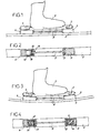
- FIG. 1 represents the central part or skid zone 2 of a ski on the upper face of which are mounted two wedges 3 and 4 respectively, made of a rigid material, and serving for the wedge 3 for mounting a stop 5 and for the wedge 4 when mounting a heel piece 6, the stop 5 and the heel piece 6 being intended to carry out, in a manner known per se, the binding of a ski boot 7.
- the wedges 3 and 4 are connected by an inextensible rod 8.
- the front end 9 of the rod 8, which is widened, is anchored inside the wedge 3, while its widened rear end 10, is disposed inside a cavity 12 formed in the wedge 4.
- the rear end of the rod 8 behaves like a piston 10, while the cavity behaves like a cylinder.
- the piston 10 bears, on the side of the rod 8, against a rigid stop 13.
- the ski when in use condition, the ski flexes, as shown in FIG. 3, the rod 8 does not disturb this movement, because its rear end 10 can slide inside the cavity 12, in direction of the back of it.
- a light 14 is provided for the passage of the rod 8 towards the interior of the wedge 4. It would be possible to replace this vertical light 14 by a horizontal axis transverse to the length of the ski for mounting the front end 9 of the rod 8 inside the wedge 3.
- FIG. 4 shows an alternative embodiment of the device of Figures 1 to 3, in which the two ends of the rod are mounted with the possibility of sliding respectively with respect to the front wedge 3 and with respect to the rear wedge 4.
- the cavities formed inside the two wedges and arranged on either side of the ends 9 and 10 respectively of the rod 8 are filled with visco-elastic material.
- the visco-elastic material 15, placed on the side of the rod is made of a hard material, having a Young's modulus between 10 9 and 10 1 () N / M 2 @ while the visco-elastic material 16 placed on the other side of the ends 9 and 10, is more flexible and has a Young's modulus between 10 7 and 10 8 N / m 2 .
- the visco-elastic material 15 allows a firm but not entirely rigid support ensuring the limitation of the distance of the wedges 3 and 4, while the visco-elastic material 16, while allowing the wedges 3 and 4 to be brought together during 'A bending movement of the ski, dampens this movement, which is favorable to avoid the vibration of the ski.
- a stud 18 of visco-elastic material is fixed to the upper face of the ski, substantially halfway between the wedges 3 and 4. When the ski flexes, this stud 18 works in extension-compression, which causes the vibration of the ski to be damped.
- FIG. 6 shows a variant of the device of Figure 5.
- a stud 19 made of a rigid material having a central and longitudinal opening 20, in which is mounted a ring 22 of visco-elastic material which encloses the rod 8 and is glued to it in its central part.
- the stud 19 is fixed to the upper face of the ski by means of a plate of visco-elastic material 23.
- the plate of visco-elastic material 23 works with extension-compression, while the ring 22 works with shearing .
- the rod 8 is mounted at its two ends on the wedges 3 and 4 by two hinge pins 24 horizontal, that is to say parallel to the upper face of the ski, and directed transversely to the ski.
- the two wedges 3 and 4 are, for their part, mounted on the ski with the interposition of a plate 25 of visco-elastic material, the two plates 25 ensuring, during deformation of the ski, taking into account their characteristics, an effect of damping of the ski by shearing because it retains the possibility of sliding relative to the two wedges 3 and 4.
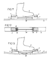
- the rod 8, the two ends of which are articulated at 24, as indicated previously, is constituted by two telescopic parts 8a and 8b, the part 8a being capable of sliding inside part 8b.
- FIG. 9 represents a first possibility, according to which the end 26 of the part 8a is capable, when mounting the boot on the ski, of coming to bear against a stop 27, while being susceptible, during a movement for bringing the two wedges 3 and 4 closer together due to a deformation of the ski, to slide inside a cavity 28.
- the stop 27a is made of a hard viscoelastic material, of a hardness corresponding to that indicated above with reference to the stop 15 of Figure 4, while the cavity 28 is partially filled with a visco-elastic material 29, more flexible than the visco-elastic material 27a, of a hardness comparable to the visco-elastic material 16 defined with reference to FIG. 4.
- FIG. 11 shows another embodiment of this device, in which the two wedges 3 and 4 are connected to each other by an inextensible cable 30, for example made of stainless steel.
- the two ends of the cable can be rigidly fixed on the two shims 3 and 4, or alternatively, as shown in FIG. 12, the front end 32 of the cable 30 can be rigidly fixed on the shim 3, while the enlarged rear end 33 of the cable 30 can bear against a visco-elastic material 34 of high hardness.
- FIG. 13 when the ski deforms in a direction of approach of the wedges 3 and 4, the cable 30 relaxes, thus in no way harming the behavior characteristics of the ski.
- the invention brings a great improvement to the existing technique by providing a device of simple design, making it possible to raise the mounting surface of the front stop and the heel of a ski, while avoiding to give this ski an excessive arrow modifying its behavior.
Landscapes
- Footwear And Its Accessory, Manufacturing Method And Apparatuses (AREA)
- Holders For Apparel And Elements Relating To Apparel (AREA)
- Axle Suspensions And Sidecars For Cycles (AREA)
- Basic Packing Technique (AREA)
Applications Claiming Priority (2)
| Application Number | Priority Date | Filing Date | Title |
|---|---|---|---|
| FR9203193A FR2688410B1 (fr) | 1992-03-10 | 1992-03-10 | Dispositif pour le montage sur un ski d'une fixation de securite, comprenant une butee et une talonniere independantes l'une de l'autre. |
| FR9203193 | 1992-03-10 |
Publications (2)
| Publication Number | Publication Date |
|---|---|
| EP0560695A1 true EP0560695A1 (de) | 1993-09-15 |
| EP0560695B1 EP0560695B1 (de) | 1997-07-09 |
Family
ID=9427776
Family Applications (1)
| Application Number | Title | Priority Date | Filing Date |
|---|---|---|---|
| EP93420097A Expired - Lifetime EP0560695B1 (de) | 1992-03-10 | 1993-03-04 | Vorrichtung enthaltend eine unabhängige Vorderbildung und Fersenhalter |
Country Status (5)
| Country | Link |
|---|---|
| US (1) | US5395132A (de) |
| EP (1) | EP0560695B1 (de) |
| AT (1) | ATE155047T1 (de) |
| DE (1) | DE69311935T2 (de) |
| FR (1) | FR2688410B1 (de) |
Cited By (3)
| Publication number | Priority date | Publication date | Assignee | Title |
|---|---|---|---|---|
| US5421602A (en) * | 1990-12-27 | 1995-06-06 | Marker Deutschland Gmbh | Support plate for a ski binding |
| US6182998B1 (en) * | 1995-12-04 | 2001-02-06 | Salomon S.A. | Shock-absorbing device for a ski or the like |
| FR2800624A1 (fr) | 1999-11-09 | 2001-05-11 | Salomon Sa | Dispositif interface entre un ski et des elements de retenue d'une chaussure sur le ski |
Families Citing this family (20)
| Publication number | Priority date | Publication date | Assignee | Title |
|---|---|---|---|---|
| DE4318513A1 (de) * | 1993-06-03 | 1994-12-08 | Marker Deutschland Gmbh | Bindungsgrundplatte |
| DE4343673A1 (de) * | 1993-12-21 | 1995-06-22 | Marker Deutschland Gmbh | Vorrichtung zur Versteifung eines Skis |
| FR2720007B1 (fr) * | 1994-05-18 | 1996-07-12 | Salomon Sa | Ski alpin muni d'un dispositif de raidissement et/ou d'amortissement à double effet. |
| FR2777472B1 (fr) * | 1998-04-17 | 2000-07-13 | Salomon Sa | Dispositif interface entre un ski et des elements de retenue d'une chaussure sur le ski |
| EP1013318A3 (de) * | 1998-12-22 | 2002-09-25 | Stephan Vogler | Bindungsplattenanordnung und Skibindung |
| EP1031360A1 (de) * | 1999-02-24 | 2000-08-30 | Roland Bünter | Skiführungsdruckverstärker-Platte (Snow-Speed) |
| FR2810893B1 (fr) * | 2000-06-28 | 2002-09-27 | Salomon Sa | Dispositif interface entre un ski alpin et des elements de retenue de la chaussure sur le ski |
| FR2810891B1 (fr) * | 2000-06-28 | 2002-09-27 | Salomon Sa | Dispositif interface entre un ski et des elements de retenue d'une chaussure sur le ski |
| ATE304888T1 (de) * | 2000-12-15 | 2005-10-15 | Marker Deutschland Gmbh | Vorrichtung zur dämpfung von flexbewegungen eines skis od.dgl. |
| FR2822387B1 (fr) * | 2001-03-20 | 2003-07-11 | Rossignol Sa | Dispositif de rehaussement d'une fixation de ski |
| US7341271B2 (en) | 2002-01-15 | 2008-03-11 | Buenter Roland | Ski spot apparatus with integrated force transmission system |
| DE10216056A1 (de) * | 2002-04-11 | 2003-10-23 | Marker Deutschland Gmbh | Basisplatte bzw.-anordnung einer Ski-oder Snowboardbindung |
| DE10236152A1 (de) * | 2002-08-07 | 2004-02-19 | Marker Deutschland Gmbh | Ski- und Skibindungs-Kombination |
| CN101102824B (zh) * | 2004-11-23 | 2010-05-12 | 安东·F·威尔逊 | 带有悬置系统的雪橇 |
| US7607679B2 (en) * | 2004-11-23 | 2009-10-27 | Anton F. Wilson | Suspension system for a ski |
| EP1850922A4 (de) * | 2005-02-16 | 2011-01-19 | Anton F Wilson | Snowboards |
| US20090045605A1 (en) * | 2007-08-17 | 2009-02-19 | Pat Keane | Snow ski |
| EP3115090B1 (de) | 2015-06-19 | 2019-01-02 | Anton F. Wilson | Sich automatisch anpassender ski |
| FR3041267B1 (fr) * | 2015-09-21 | 2019-05-24 | Skis Rossignol | Dispositif amortisseur destine a etre monte sur une planche de glisse sur neige |
| US12458867B1 (en) * | 2025-07-25 | 2025-11-04 | Chris Stevens Simon | Ski bracket system |
Citations (4)
| Publication number | Priority date | Publication date | Assignee | Title |
|---|---|---|---|---|
| FR2105801A5 (de) * | 1970-09-28 | 1972-04-28 | Smolka & Co Wiener Metall | |
| DE3710092A1 (de) * | 1987-03-27 | 1988-10-06 | Dietrich Von Puttkamer | Ski |
| FR2639242A1 (fr) * | 1988-11-18 | 1990-05-25 | Rossignol Sa | Ensemble perfectionne pour la pratique du ski, constitue par une chaussure et un ski |
| DE9102551U1 (de) * | 1991-03-04 | 1991-05-23 | Blizzard Ges.m.b.H., Mittersill | Ski |
Family Cites Families (2)
| Publication number | Priority date | Publication date | Assignee | Title |
|---|---|---|---|---|
| AT400524B (de) * | 1988-10-10 | 1996-01-25 | Atomic Austria Gmbh | Schi |
| US5269555A (en) * | 1991-06-14 | 1993-12-14 | Ruffinengo Piero G | Modification of the flexibility of skis |
-
1992
- 1992-03-10 FR FR9203193A patent/FR2688410B1/fr not_active Expired - Fee Related
-
1993
- 1993-03-04 EP EP93420097A patent/EP0560695B1/de not_active Expired - Lifetime
- 1993-03-04 AT AT93420097T patent/ATE155047T1/de not_active IP Right Cessation
- 1993-03-04 DE DE69311935T patent/DE69311935T2/de not_active Expired - Fee Related
- 1993-03-08 US US08/028,929 patent/US5395132A/en not_active Expired - Lifetime
Patent Citations (4)
| Publication number | Priority date | Publication date | Assignee | Title |
|---|---|---|---|---|
| FR2105801A5 (de) * | 1970-09-28 | 1972-04-28 | Smolka & Co Wiener Metall | |
| DE3710092A1 (de) * | 1987-03-27 | 1988-10-06 | Dietrich Von Puttkamer | Ski |
| FR2639242A1 (fr) * | 1988-11-18 | 1990-05-25 | Rossignol Sa | Ensemble perfectionne pour la pratique du ski, constitue par une chaussure et un ski |
| DE9102551U1 (de) * | 1991-03-04 | 1991-05-23 | Blizzard Ges.m.b.H., Mittersill | Ski |
Cited By (4)
| Publication number | Priority date | Publication date | Assignee | Title |
|---|---|---|---|---|
| US5421602A (en) * | 1990-12-27 | 1995-06-06 | Marker Deutschland Gmbh | Support plate for a ski binding |
| US5651560A (en) * | 1990-12-27 | 1997-07-29 | Marker Deutschland Gmbh | Support plate for a ski binding |
| US6182998B1 (en) * | 1995-12-04 | 2001-02-06 | Salomon S.A. | Shock-absorbing device for a ski or the like |
| FR2800624A1 (fr) | 1999-11-09 | 2001-05-11 | Salomon Sa | Dispositif interface entre un ski et des elements de retenue d'une chaussure sur le ski |
Also Published As
| Publication number | Publication date |
|---|---|
| EP0560695B1 (de) | 1997-07-09 |
| DE69311935D1 (de) | 1997-08-14 |
| US5395132A (en) | 1995-03-07 |
| FR2688410B1 (fr) | 1994-05-06 |
| DE69311935T2 (de) | 1997-11-06 |
| ATE155047T1 (de) | 1997-07-15 |
| FR2688410A1 (fr) | 1993-09-17 |
Similar Documents
| Publication | Publication Date | Title |
|---|---|---|
| EP0560695B1 (de) | Vorrichtung enthaltend eine unabhängige Vorderbildung und Fersenhalter | |
| EP1166668A2 (de) | Sportschuh mit einer an einer flexiblen Fersenkappe befestigten steifen Fersenkappe | |
| FR2613914A1 (fr) | Chaussure de ski alpin | |
| WO1993014837A1 (fr) | Dispositif pour modifier la repartition d'un ski sur sa surface de glisse | |
| FR2595256A1 (fr) | Dispositif de fixation de securite pour monoskis | |
| FR2802108A1 (fr) | Dispositif de retenue d'une chaussure sur une planche de glisse | |
| EP0658360A1 (de) | Vorrichtung zwischen Ski und Bindung | |
| EP1155716B1 (de) | Vorrichtung zum Erhöhen von mindestens einer Ski Bindung zur Verwendung auf einem Gleitbrett | |
| EP1013316B1 (de) | Alpinski | |
| EP0634196B1 (de) | Bindungselement für einen alphinen Ski | |
| FR2583296A1 (fr) | Ski, notamment a usage de ski alpin | |
| FR2513133A1 (fr) | Machoire avant pour des fixations de ski de securite | |
| EP0544063B1 (de) | Sicherheitsbindung für Alpinski | |
| EP0436444B1 (de) | Skischuh aus Kunststoff | |
| FR2810206A1 (fr) | Chaussure pour la pratique du surf des neiges | |
| FR2796852A1 (fr) | Dispositif interface entre une chaussure et un ski | |
| EP0672437B1 (de) | Vorrichtung zum Veränderen der natürlichen Druckverteilung eines Skis aus Schnee | |
| EP1810726B1 (de) | Vorrichtung zum Festhalten von Schuhe auf einem Snowboard | |
| EP0571736B1 (de) | Flexionsvorrichtung für Schischuhe | |
| FR2768937A1 (fr) | Plot amortisseur destine a etre monte sur un article de sport, tel que notamment un ski equipe d'une plate-forme ou une platine de patin a roulettes | |
| FR2755026A1 (fr) | Planche de glisse sur neige equipee d'une plate-forme de reception et de surelevation des fixations de la chaussure | |
| FR2800624A1 (fr) | Dispositif interface entre un ski et des elements de retenue d'une chaussure sur le ski | |
| FR2759600A1 (fr) | Plaque de surelevation en deux parties pour ski de neige | |
| FR2739301A1 (fr) | Element et ensemble de retenue d'une chaussure sur une planche de glisse | |
| FR2578749A2 (fr) | Machoire avant pour fixations de securite de ski |
Legal Events
| Date | Code | Title | Description |
|---|---|---|---|
| PUAI | Public reference made under article 153(3) epc to a published international application that has entered the european phase |
Free format text: ORIGINAL CODE: 0009012 |
|
| 17P | Request for examination filed |
Effective date: 19930714 |
|
| AK | Designated contracting states |
Kind code of ref document: A1 Designated state(s): AT CH DE LI |
|
| 17Q | First examination report despatched |
Effective date: 19940511 |
|
| GRAG | Despatch of communication of intention to grant |
Free format text: ORIGINAL CODE: EPIDOS AGRA |
|
| GRAH | Despatch of communication of intention to grant a patent |
Free format text: ORIGINAL CODE: EPIDOS IGRA |
|
| GRAH | Despatch of communication of intention to grant a patent |
Free format text: ORIGINAL CODE: EPIDOS IGRA |
|
| GRAA | (expected) grant |
Free format text: ORIGINAL CODE: 0009210 |
|
| AK | Designated contracting states |
Kind code of ref document: B1 Designated state(s): AT CH DE LI |
|
| REF | Corresponds to: |
Ref document number: 155047 Country of ref document: AT Date of ref document: 19970715 Kind code of ref document: T |
|
| REG | Reference to a national code |
Ref country code: CH Ref legal event code: EP |
|
| REF | Corresponds to: |
Ref document number: 69311935 Country of ref document: DE Date of ref document: 19970814 |
|
| PG25 | Lapsed in a contracting state [announced via postgrant information from national office to epo] |
Ref country code: LI Free format text: LAPSE BECAUSE OF NON-PAYMENT OF DUE FEES Effective date: 19980331 Ref country code: CH Free format text: LAPSE BECAUSE OF NON-PAYMENT OF DUE FEES Effective date: 19980331 |
|
| PLBE | No opposition filed within time limit |
Free format text: ORIGINAL CODE: 0009261 |
|
| STAA | Information on the status of an ep patent application or granted ep patent |
Free format text: STATUS: NO OPPOSITION FILED WITHIN TIME LIMIT |
|
| 26N | No opposition filed | ||
| REG | Reference to a national code |
Ref country code: CH Ref legal event code: PL |
|
| PGFP | Annual fee paid to national office [announced via postgrant information from national office to epo] |
Ref country code: AT Payment date: 20070219 Year of fee payment: 15 |
|
| PGFP | Annual fee paid to national office [announced via postgrant information from national office to epo] |
Ref country code: DE Payment date: 20080311 Year of fee payment: 16 |
|
| PG25 | Lapsed in a contracting state [announced via postgrant information from national office to epo] |
Ref country code: AT Free format text: LAPSE BECAUSE OF NON-PAYMENT OF DUE FEES Effective date: 20080304 |
|
| PG25 | Lapsed in a contracting state [announced via postgrant information from national office to epo] |
Ref country code: DE Free format text: LAPSE BECAUSE OF NON-PAYMENT OF DUE FEES Effective date: 20091001 |