EP0457148A1 - Dispositif pour le réglage de débit et/ou de pression avec un tiroir - Google Patents
Dispositif pour le réglage de débit et/ou de pression avec un tiroir Download PDFInfo
- Publication number
- EP0457148A1 EP0457148A1 EP91107300A EP91107300A EP0457148A1 EP 0457148 A1 EP0457148 A1 EP 0457148A1 EP 91107300 A EP91107300 A EP 91107300A EP 91107300 A EP91107300 A EP 91107300A EP 0457148 A1 EP0457148 A1 EP 0457148A1
- Authority
- EP
- European Patent Office
- Prior art keywords
- slide
- switch
- blading
- pilot
- slide switch
- Prior art date
- Legal status (The legal status is an assumption and is not a legal conclusion. Google has not performed a legal analysis and makes no representation as to the accuracy of the status listed.)
- Granted
Links
- 239000012530 fluid Substances 0.000 claims abstract description 4
- 230000005540 biological transmission Effects 0.000 claims abstract description 3
- 230000033001 locomotion Effects 0.000 claims description 8
- 239000002184 metal Substances 0.000 claims description 2
- 230000000694 effects Effects 0.000 abstract description 6
- 238000007789 sealing Methods 0.000 abstract description 4
- 239000002245 particle Substances 0.000 abstract description 3
- 238000009825 accumulation Methods 0.000 abstract 1
- 230000006835 compression Effects 0.000 description 2
- 238000007906 compression Methods 0.000 description 2
- 239000010720 hydraulic oil Substances 0.000 description 2
- 230000001105 regulatory effect Effects 0.000 description 2
- 230000002411 adverse Effects 0.000 description 1
- 230000007423 decrease Effects 0.000 description 1
- 238000004519 manufacturing process Methods 0.000 description 1
- 239000003921 oil Substances 0.000 description 1
- 230000003068 static effect Effects 0.000 description 1
Images
Classifications
-
- F—MECHANICAL ENGINEERING; LIGHTING; HEATING; WEAPONS; BLASTING
- F16—ENGINEERING ELEMENTS AND UNITS; GENERAL MEASURES FOR PRODUCING AND MAINTAINING EFFECTIVE FUNCTIONING OF MACHINES OR INSTALLATIONS; THERMAL INSULATION IN GENERAL
- F16K—VALVES; TAPS; COCKS; ACTUATING-FLOATS; DEVICES FOR VENTING OR AERATING
- F16K29/00—Arrangements for movement of valve members other than for opening and closing the valve, e.g. for grinding-in, for preventing sticking
- F16K29/02—Arrangements for movement of valve members other than for opening and closing the valve, e.g. for grinding-in, for preventing sticking providing for continuous motion
Definitions
- the invention relates to a device for volume and / or pressure control according to the preamble of patent claim 1.
- Switching elements controlled by hydraulic systems require a certain working pressure or a certain working volume. This is supplied or regulated via switching devices, in which, for example, a slide switch is slidably arranged in a housing channel and which, depending on its axial position, closes or keeps open lines connected to the housing channel.
- switching devices in which, for example, a slide switch is slidably arranged in a housing channel and which, depending on its axial position, closes or keeps open lines connected to the housing channel.
- Known devices of this type have the so-called stick-and-slip effect as a major disadvantage.
- the slide switch rests at least in sections on an inner wall of the housing channel.
- a certain breakaway force is required due to the existing static friction.
- the control behavior is adversely affected by the described effect.
- the object of the present invention is to avoid the described effect in a device of the type mentioned at the outset.
- the object is achieved by the characterizing features of patent claim 1.
- the rotation of the slide switch provided according to the invention about its longitudinal axis brings about a hydrodynamic mounting within the housing channel.
- the stick-and-slip effect is avoided because at most sliding friction between the slide switch and the inner wall of the housing channel consists.
- the rotation of the slide switch results in a uniform sealing gap, which also prevents one-sided wear of the slide or the housing channel.
- the rotation effectively prevents dirt particles from getting stuck in the sealing gap.
- a preferred field of application of the invention is the hydraulic control of shifting elements for automatic transmissions, in particular of motor vehicles.
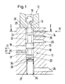
- a slide switch 10 is arranged axially displaceably in a housing channel 11.
- the slide switch 10 is adjusted via an electromagnetic valve 12, the inlet 13 of which is arranged in a continuation of the housing channel 11 and above the same.
- a hydraulic fluid flowing into the pilot control inlet 14 in the direction of the arrow 15 is regulated in its pressure by a ball 16 movable in the electromagnetic valve 12.
- the pressure within the pilot control inlet 14 increases and the slide valve 10 moves downwards in the axial direction.
- a pressure line 17 leading laterally to the housing channel 11 supplies a switching element line 18 arranged above it and leading away from the housing channel 11. The flow rate depends on the position of the slide switch 10.
- the switching element line 18 is provided with a control edge 20 known per se in its lower region, that is, where the control collar 19 first releases a specific cross section.
- the flow directions in the lines 17, 18 shown by the arrows 21, 22 result 14 lying top control collar 24.
- Return lines 25, 26 are provided between the upper control collar 24 and the control collar 19 and below the lower control collar 23 for returning leakage oil to a hydraulic tank (not shown).
- a compression spring 27 is arranged in the housing channel 11 below the slide switch 10 and counteracts the pilot pressure acting on the slide valve 10 from above.
- the slide switch 10 In order to avoid jamming of the slide switch 10, it is rotatably mounted in the housing channel 11.
- the rotational movement is generated by the hydraulic oil flowing in via the pilot control inlet 14 and outflowing via the electromagnetic valve 12 in connection with a special shape of the slide 10 in the area (switching slide head 28) above the upper control collar 24.
- the switching slide head 28 is equipped with blading 29 provided, which sets the slide valve 10 in rotary motion via the inflow from the pilot control inlet 14.
- FIG. 2 shows a cross section of the blading 29. This results from two semicircles 30, 31 which are offset with respect to one another along their half diameter.
- the rotation of the slide switch 10 brings about a hydrodynamic mounting overall. As a result, the so-called stick-and-slip effect is avoided and an even sealing gap is achieved all around. A sticking of dirt particles between the slide switch 10 and the inner wall 32 of the housing channel 11 is avoided and one-sided housing wear is prevented.
- the slide switch 10 is made in one piece with the blading 29.
- the blades 29 are applied to the slide switch 10 after production, e.g. clipped on.
- the blading 29 consists of sheet metal or plastic. Switch slide and blading can be manufactured particularly cheaply.
- the compression spring 27 does not press directly against the lower control collar 23. Rather, a point support is provided in this area, which is achieved by a hemisphere 34 under the lower control collar 23 pressing against a spring plate 33.
- a drain 35 is provided below the pilot control inlet 14. As soon as the upper control collar 24 releases at least part of the cross section of this outlet 35, the pressure acting on the slide valve 10 from above also decreases, so that the downward movement is stopped.
- a stop connected to the spring plate 3 for limiting the stroke of the slide switch 10 is provided instead of the outlet 35.
- the maximum stroke of the slide switch 10 then ends when the stop abuts against the lower end 36 of the housing channel 11.
- the blading 29 described can also be provided on other areas of the slide valve 10 against which the flow is directed, in particular between the lower control collar 23 and the upper control collar 24 for the inflow through the pressure line 17.
- a supply of the hydraulic oil is particularly advantageous, in which the corresponding line is eccentrically in the Housing channel 11 is inserted.
- the pilot control inlet 14 is on the side staggered so that the flow energy can be fully used to generate the rotation. With blading in the area below the control collar 19, such an eccentric supply of the pressure line 17 to the housing channel 11 would also be advantageous.
Landscapes
- Engineering & Computer Science (AREA)
- General Engineering & Computer Science (AREA)
- Mechanical Engineering (AREA)
- Control Of Transmission Device (AREA)
- Multiple-Way Valves (AREA)
- Control Of Fluid Gearings (AREA)
- Gear-Shifting Mechanisms (AREA)
Applications Claiming Priority (2)
| Application Number | Priority Date | Filing Date | Title |
|---|---|---|---|
| DE4016068 | 1990-05-18 | ||
| DE4016068 | 1990-05-18 |
Publications (2)
| Publication Number | Publication Date |
|---|---|
| EP0457148A1 true EP0457148A1 (fr) | 1991-11-21 |
| EP0457148B1 EP0457148B1 (fr) | 1994-12-28 |
Family
ID=6406748
Family Applications (1)
| Application Number | Title | Priority Date | Filing Date |
|---|---|---|---|
| EP91107300A Expired - Lifetime EP0457148B1 (fr) | 1990-05-18 | 1991-05-06 | Dispositif pour le réglage de débit et/ou de pression avec un tiroir |
Country Status (3)
| Country | Link |
|---|---|
| EP (1) | EP0457148B1 (fr) |
| DE (1) | DE59104018D1 (fr) |
| ES (1) | ES2067082T3 (fr) |
Cited By (2)
| Publication number | Priority date | Publication date | Assignee | Title |
|---|---|---|---|---|
| FR2718190A1 (fr) * | 1994-04-01 | 1995-10-06 | Snecma | Soupape de régulation d'injection de carburant pour une turbomachine. |
| EP1803981A2 (fr) | 2005-12-29 | 2007-07-04 | Eaton Corporation | Soupape de régulation de pression |
Citations (3)
| Publication number | Priority date | Publication date | Assignee | Title |
|---|---|---|---|---|
| FR1038055A (fr) * | 1951-06-04 | 1953-09-24 | Valve hydraulique auto-activée | |
| US3051191A (en) * | 1958-06-11 | 1962-08-28 | Daimler Benz Ag | Pressure regulating slide valve, especially for automatic control mechanisms for shifting the gears of motor vehicles |
| DE1945038A1 (de) * | 1969-09-05 | 1971-03-11 | Miele & Cie | Verfahren zum Reinigen von wasserunloeslichen Verschmutzungen in Geschirrspuelmaschinen |
-
1991
- 1991-05-06 ES ES91107300T patent/ES2067082T3/es not_active Expired - Lifetime
- 1991-05-06 EP EP91107300A patent/EP0457148B1/fr not_active Expired - Lifetime
- 1991-05-06 DE DE59104018T patent/DE59104018D1/de not_active Expired - Fee Related
Patent Citations (3)
| Publication number | Priority date | Publication date | Assignee | Title |
|---|---|---|---|---|
| FR1038055A (fr) * | 1951-06-04 | 1953-09-24 | Valve hydraulique auto-activée | |
| US3051191A (en) * | 1958-06-11 | 1962-08-28 | Daimler Benz Ag | Pressure regulating slide valve, especially for automatic control mechanisms for shifting the gears of motor vehicles |
| DE1945038A1 (de) * | 1969-09-05 | 1971-03-11 | Miele & Cie | Verfahren zum Reinigen von wasserunloeslichen Verschmutzungen in Geschirrspuelmaschinen |
Cited By (4)
| Publication number | Priority date | Publication date | Assignee | Title |
|---|---|---|---|---|
| FR2718190A1 (fr) * | 1994-04-01 | 1995-10-06 | Snecma | Soupape de régulation d'injection de carburant pour une turbomachine. |
| US5548959A (en) * | 1994-04-01 | 1996-08-27 | Societe Nationale D'etude Et De Construction De Moteurs D'aviation "Snecma" | Adjustment valve for injecting fuel for a turbojet engine |
| EP1803981A2 (fr) | 2005-12-29 | 2007-07-04 | Eaton Corporation | Soupape de régulation de pression |
| EP1803981A3 (fr) * | 2005-12-29 | 2008-03-19 | Eaton Corporation | Soupape de régulation de pression |
Also Published As
| Publication number | Publication date |
|---|---|
| ES2067082T3 (es) | 1995-03-16 |
| DE59104018D1 (de) | 1995-02-09 |
| EP0457148B1 (fr) | 1994-12-28 |
Similar Documents
| Publication | Publication Date | Title |
|---|---|---|
| EP1760312B1 (fr) | Pompe haute pression | |
| DE10161131B4 (de) | Flügelpumpe veränderlicher Verdrängung | |
| DE19632099A1 (de) | Luftsteuerventil | |
| DE2808810A1 (de) | Variables riemenscheibengetriebe | |
| DE69217946T2 (de) | Rückführventil | |
| DE102004059119B4 (de) | Elektromagnetventil | |
| EP2848787A1 (fr) | Soupape de commande pour une buse de lubrifiant | |
| EP1072796B1 (fr) | Procédé de commande d'un compresseur à vis | |
| DE102006061326B4 (de) | Stelleneinrichtung für eine mengenregelbare Zellenpumpe | |
| DE602005003152T2 (de) | Rückschlagventil | |
| EP1148251B1 (fr) | Soupape de commande de pression | |
| EP2483558B1 (fr) | Pompe por une appareil de nettoyage haute pression | |
| EP0130306B2 (fr) | Procédé et dispositif pour contrôler un séparateur de tubes | |
| DE4446152C2 (de) | Heizsystem, insbesondere für Kraftfahrzeuge | |
| DE60024068T2 (de) | Verdichter und verfahren zur schmierung des verdichters | |
| EP0457148B1 (fr) | Dispositif pour le réglage de débit et/ou de pression avec un tiroir | |
| EP0278333B1 (fr) | Dispositif de commande pour un séparateur de tuyau | |
| DE10219667A1 (de) | Expansionsventil | |
| DE3211948C2 (de) | Regeleinrichtung für eine Verdrängerpumpe, insbesondere Flügelzellenpumpe | |
| WO2020043329A1 (fr) | Soupape | |
| DE69202647T2 (de) | Zwei-Geschwindigkeitshubfahrtsteuereinrichtung für einen hydraulischen Aufzug. | |
| DE102005013861B4 (de) | Schrittmotor-Kühleinrichtung und zugehöriges Verfahren für ein stufenloses Riemengetriebe | |
| DE9301796U1 (de) | Hochdruckreinigungsgerät | |
| DE1033469B (de) | Vorrichtung zur selbsttaetigen Regelung der Zufuhr von Schmieroel zu Motoren, Dampfkraftmaschinen oder sonstigen Maschinen mit Druckoelschmierung | |
| EP0323591A2 (fr) | Dispositif de réglage de l'injection à 2 points |
Legal Events
| Date | Code | Title | Description |
|---|---|---|---|
| PUAI | Public reference made under article 153(3) epc to a published international application that has entered the european phase |
Free format text: ORIGINAL CODE: 0009012 |
|
| AK | Designated contracting states |
Kind code of ref document: A1 Designated state(s): DE ES FR GB IT |
|
| 17P | Request for examination filed |
Effective date: 19920219 |
|
| 17Q | First examination report despatched |
Effective date: 19931021 |
|
| GRAA | (expected) grant |
Free format text: ORIGINAL CODE: 0009210 |
|
| AK | Designated contracting states |
Kind code of ref document: B1 Designated state(s): DE ES FR GB IT |
|
| REF | Corresponds to: |
Ref document number: 59104018 Country of ref document: DE Date of ref document: 19950209 |
|
| REG | Reference to a national code |
Ref country code: ES Ref legal event code: FG2A Ref document number: 2067082 Country of ref document: ES Kind code of ref document: T3 |
|
| ET | Fr: translation filed | ||
| ITF | It: translation for a ep patent filed | ||
| GBT | Gb: translation of ep patent filed (gb section 77(6)(a)/1977) |
Effective date: 19950328 |
|
| PLBE | No opposition filed within time limit |
Free format text: ORIGINAL CODE: 0009261 |
|
| STAA | Information on the status of an ep patent application or granted ep patent |
Free format text: STATUS: NO OPPOSITION FILED WITHIN TIME LIMIT |
|
| 26N | No opposition filed | ||
| PGFP | Annual fee paid to national office [announced via postgrant information from national office to epo] |
Ref country code: GB Payment date: 19960424 Year of fee payment: 6 |
|
| PGFP | Annual fee paid to national office [announced via postgrant information from national office to epo] |
Ref country code: FR Payment date: 19960517 Year of fee payment: 6 |
|
| PGFP | Annual fee paid to national office [announced via postgrant information from national office to epo] |
Ref country code: ES Payment date: 19960531 Year of fee payment: 6 |
|
| PG25 | Lapsed in a contracting state [announced via postgrant information from national office to epo] |
Ref country code: GB Effective date: 19970506 |
|
| PG25 | Lapsed in a contracting state [announced via postgrant information from national office to epo] |
Ref country code: ES Free format text: LAPSE BECAUSE OF NON-PAYMENT OF DUE FEES Effective date: 19970507 |
|
| GBPC | Gb: european patent ceased through non-payment of renewal fee |
Effective date: 19970506 |
|
| PG25 | Lapsed in a contracting state [announced via postgrant information from national office to epo] |
Ref country code: FR Free format text: LAPSE BECAUSE OF NON-PAYMENT OF DUE FEES Effective date: 19980130 |
|
| REG | Reference to a national code |
Ref country code: FR Ref legal event code: ST |
|
| REG | Reference to a national code |
Ref country code: ES Ref legal event code: FD2A Effective date: 19990405 |
|
| PGFP | Annual fee paid to national office [announced via postgrant information from national office to epo] |
Ref country code: DE Payment date: 20000527 Year of fee payment: 10 |
|
| PG25 | Lapsed in a contracting state [announced via postgrant information from national office to epo] |
Ref country code: DE Free format text: LAPSE BECAUSE OF NON-PAYMENT OF DUE FEES Effective date: 20020301 |
|
| PG25 | Lapsed in a contracting state [announced via postgrant information from national office to epo] |
Ref country code: IT Free format text: LAPSE BECAUSE OF NON-PAYMENT OF DUE FEES Effective date: 20050506 |