EP0457148A1 - Vorrichtung zur Volumen- und/oder Drucksteuerung mit einem Schaltschieber - Google Patents
Vorrichtung zur Volumen- und/oder Drucksteuerung mit einem Schaltschieber Download PDFInfo
- Publication number
- EP0457148A1 EP0457148A1 EP91107300A EP91107300A EP0457148A1 EP 0457148 A1 EP0457148 A1 EP 0457148A1 EP 91107300 A EP91107300 A EP 91107300A EP 91107300 A EP91107300 A EP 91107300A EP 0457148 A1 EP0457148 A1 EP 0457148A1
- Authority
- EP
- European Patent Office
- Prior art keywords
- slide
- switch
- blading
- pilot
- slide switch
- Prior art date
- Legal status (The legal status is an assumption and is not a legal conclusion. Google has not performed a legal analysis and makes no representation as to the accuracy of the status listed.)
- Granted
Links
- 239000012530 fluid Substances 0.000 claims abstract description 4
- 230000005540 biological transmission Effects 0.000 claims abstract description 3
- 230000033001 locomotion Effects 0.000 claims description 8
- 239000002184 metal Substances 0.000 claims description 2
- 230000000694 effects Effects 0.000 abstract description 6
- 238000007789 sealing Methods 0.000 abstract description 4
- 239000002245 particle Substances 0.000 abstract description 3
- 238000009825 accumulation Methods 0.000 abstract 1
- 230000006835 compression Effects 0.000 description 2
- 238000007906 compression Methods 0.000 description 2
- 239000010720 hydraulic oil Substances 0.000 description 2
- 230000001105 regulatory effect Effects 0.000 description 2
- 230000002411 adverse Effects 0.000 description 1
- 230000007423 decrease Effects 0.000 description 1
- 238000004519 manufacturing process Methods 0.000 description 1
- 239000003921 oil Substances 0.000 description 1
- 230000003068 static effect Effects 0.000 description 1
Images
Classifications
-
- F—MECHANICAL ENGINEERING; LIGHTING; HEATING; WEAPONS; BLASTING
- F16—ENGINEERING ELEMENTS AND UNITS; GENERAL MEASURES FOR PRODUCING AND MAINTAINING EFFECTIVE FUNCTIONING OF MACHINES OR INSTALLATIONS; THERMAL INSULATION IN GENERAL
- F16K—VALVES; TAPS; COCKS; ACTUATING-FLOATS; DEVICES FOR VENTING OR AERATING
- F16K29/00—Arrangements for movement of valve members other than for opening and closing the valve, e.g. for grinding-in, for preventing sticking
- F16K29/02—Arrangements for movement of valve members other than for opening and closing the valve, e.g. for grinding-in, for preventing sticking providing for continuous motion
Definitions
- the invention relates to a device for volume and / or pressure control according to the preamble of patent claim 1.
- Switching elements controlled by hydraulic systems require a certain working pressure or a certain working volume. This is supplied or regulated via switching devices, in which, for example, a slide switch is slidably arranged in a housing channel and which, depending on its axial position, closes or keeps open lines connected to the housing channel.
- switching devices in which, for example, a slide switch is slidably arranged in a housing channel and which, depending on its axial position, closes or keeps open lines connected to the housing channel.
- Known devices of this type have the so-called stick-and-slip effect as a major disadvantage.
- the slide switch rests at least in sections on an inner wall of the housing channel.
- a certain breakaway force is required due to the existing static friction.
- the control behavior is adversely affected by the described effect.
- the object of the present invention is to avoid the described effect in a device of the type mentioned at the outset.
- the object is achieved by the characterizing features of patent claim 1.
- the rotation of the slide switch provided according to the invention about its longitudinal axis brings about a hydrodynamic mounting within the housing channel.
- the stick-and-slip effect is avoided because at most sliding friction between the slide switch and the inner wall of the housing channel consists.
- the rotation of the slide switch results in a uniform sealing gap, which also prevents one-sided wear of the slide or the housing channel.
- the rotation effectively prevents dirt particles from getting stuck in the sealing gap.
- a preferred field of application of the invention is the hydraulic control of shifting elements for automatic transmissions, in particular of motor vehicles.
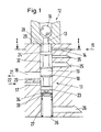
- a slide switch 10 is arranged axially displaceably in a housing channel 11.
- the slide switch 10 is adjusted via an electromagnetic valve 12, the inlet 13 of which is arranged in a continuation of the housing channel 11 and above the same.
- a hydraulic fluid flowing into the pilot control inlet 14 in the direction of the arrow 15 is regulated in its pressure by a ball 16 movable in the electromagnetic valve 12.
- the pressure within the pilot control inlet 14 increases and the slide valve 10 moves downwards in the axial direction.
- a pressure line 17 leading laterally to the housing channel 11 supplies a switching element line 18 arranged above it and leading away from the housing channel 11. The flow rate depends on the position of the slide switch 10.
- the switching element line 18 is provided with a control edge 20 known per se in its lower region, that is, where the control collar 19 first releases a specific cross section.
- the flow directions in the lines 17, 18 shown by the arrows 21, 22 result 14 lying top control collar 24.
- Return lines 25, 26 are provided between the upper control collar 24 and the control collar 19 and below the lower control collar 23 for returning leakage oil to a hydraulic tank (not shown).
- a compression spring 27 is arranged in the housing channel 11 below the slide switch 10 and counteracts the pilot pressure acting on the slide valve 10 from above.
- the slide switch 10 In order to avoid jamming of the slide switch 10, it is rotatably mounted in the housing channel 11.
- the rotational movement is generated by the hydraulic oil flowing in via the pilot control inlet 14 and outflowing via the electromagnetic valve 12 in connection with a special shape of the slide 10 in the area (switching slide head 28) above the upper control collar 24.
- the switching slide head 28 is equipped with blading 29 provided, which sets the slide valve 10 in rotary motion via the inflow from the pilot control inlet 14.
- FIG. 2 shows a cross section of the blading 29. This results from two semicircles 30, 31 which are offset with respect to one another along their half diameter.
- the rotation of the slide switch 10 brings about a hydrodynamic mounting overall. As a result, the so-called stick-and-slip effect is avoided and an even sealing gap is achieved all around. A sticking of dirt particles between the slide switch 10 and the inner wall 32 of the housing channel 11 is avoided and one-sided housing wear is prevented.
- the slide switch 10 is made in one piece with the blading 29.
- the blades 29 are applied to the slide switch 10 after production, e.g. clipped on.
- the blading 29 consists of sheet metal or plastic. Switch slide and blading can be manufactured particularly cheaply.
- the compression spring 27 does not press directly against the lower control collar 23. Rather, a point support is provided in this area, which is achieved by a hemisphere 34 under the lower control collar 23 pressing against a spring plate 33.
- a drain 35 is provided below the pilot control inlet 14. As soon as the upper control collar 24 releases at least part of the cross section of this outlet 35, the pressure acting on the slide valve 10 from above also decreases, so that the downward movement is stopped.
- a stop connected to the spring plate 3 for limiting the stroke of the slide switch 10 is provided instead of the outlet 35.
- the maximum stroke of the slide switch 10 then ends when the stop abuts against the lower end 36 of the housing channel 11.
- the blading 29 described can also be provided on other areas of the slide valve 10 against which the flow is directed, in particular between the lower control collar 23 and the upper control collar 24 for the inflow through the pressure line 17.
- a supply of the hydraulic oil is particularly advantageous, in which the corresponding line is eccentrically in the Housing channel 11 is inserted.
- the pilot control inlet 14 is on the side staggered so that the flow energy can be fully used to generate the rotation. With blading in the area below the control collar 19, such an eccentric supply of the pressure line 17 to the housing channel 11 would also be advantageous.
Landscapes
- Engineering & Computer Science (AREA)
- General Engineering & Computer Science (AREA)
- Mechanical Engineering (AREA)
- Control Of Transmission Device (AREA)
- Multiple-Way Valves (AREA)
- Control Of Fluid Gearings (AREA)
- Gear-Shifting Mechanisms (AREA)
Abstract
Description
- Die Erfindung betrifft eine Vorrichtung zur Volumen- und/oder Drucksteuerung gemäß dem Oberbegriff des Patentanspruchs 1.
- Durch hydraulische Systeme gesteuerte Schaltglieder benötigen einen bestimmten Arbeitsdruck bzw. ein bestimmtes Arbeitsvolumen. Dieses wird zugeführt bzw. geregelt über Schaltvorrichtungen, bei denen beispielsweise ein Schaltschieber in einem Gehäusekanal verschiebbar angeordnet ist und der in Abhängigkeit von seiner axialen Position mit dem Gehäusekanal verbundene Leitungen abschließt oder offenhält. Bekannte Vorrichtungen dieser Art weisen als großen Nachteil den sogenannten Stick-and-Slip-Effekt auf. Der Schaltschieber liegt im Ruhezustand zumindest abschnittsweise an einer Innenwandung des Gehäusekanals an. Zu Beginn einer axialen Bewegung ist aufgrund der vorhandenen Haftreibung eine bestimmte Losbrechkraft erforderlich. Insbesondere bei Einbau der Vorrichtung in einen Regelkreis wird das Regelverhalten durch den beschriebenen Effekt nachteilig beeinflußt.
- Aufgabe der vorliegenden Erfindung ist es, bei einer Vorrichtung der eingangs genannten Art den beschriebenen Effekt zu vermeiden. Die Aufgabe wird gelöst durch die kennzeichnenden Merkmale des Patentanspruchs 1. Die erfindungsgemäß vorgesehene Rotation des Schaltschiebers um seine Längsachse bewirkt eine hydrodynamische Lagerung innerhalb des Gehäusekanals. Der Stick-and-Slip-Effekt wird vermieden, weil zwischen dem Schaltschieber und der Innenwandung des Gehäusekanals allenfalls noch Gleitreibung besteht. Darüber hinaus ergibt sich durch die Rotation des Schaltschiebers ein gleichmäßiger Dichtspalt, durch den zudem ein einseitiger Verschleiß des Schiebers oder des Gehäusekanals vermieden wird. Weiterhin wird durch die Rotation ein Festsetzen von Schmutzpartikeln im Dichtspalt wirksam verhindert.
- Vorteilhafte Ausgestaltungen der Erfindung sind den Unteransprüchen zu entnehmen.
- Eine Ausführungsform der Erfindung wird im folgenden anhand von Zeichnungen näher erlautert. Es zeigen:
- Figur 1:
- eine erfindungsgemäße Vorrichtung mit einem in einem Gehäusekanal angeordneten Schaltschieber im Längsschnitt,
- Figur 2:
- den Schaltschieber im Querschnitt gemäß Figur 1 entlang der Linie I-I.
- Ein bevorzugtes Anwendungsgebiet der Erfindung liegt in der hydraulischen Steuerung von Schaltgliedern für automatische Getriebe, insbesondere von Kraftfahrzeugen.
- Gemäß Figur 1 ist ein Schaltschieber 10 in einem Gehäusekanal 11 axial verschiebbar angeordnet. Eine Verstellung des Schaltschiebers 10 erfolgt über ein elektromagnetisches Ventil 12, dessen Zulauf 13 in Fortsetzung des Gehäusekanals 11 und oberhalb desselben angeordnet ist. Eine in den Vorsteuerzulauf 14 in Richtung des Pfeils 15 einströmende Hydraulikflüssigkeit wird durch eine im elektromagnetischen Ventil 12 bewegliche Kugel 16 in ihrem Druck geregelt. Bei einer elektromagnetisch bewirkten Absenkung der Kugel 16 in Richtung des Schaltschiebers 10 erhöht sich der Druck innerhalb des Vorsteuerzulaufs 14 und der Schaltschieber 10 bewegt sich in axialer Richtung nach unten. Eine seitlich zu dem Gehäusekanal 11 hin führende Druckleitung 17 versorgt eine darüber angeordnete und von dem Gehäusekanal 11 wegführende Schaltgliedleitung 18. Die Durchflußmenge ist abhängig von der Position des Schaltschiebers 10. Dieser weist einen Steuerbund 19 auf, durch den die Schaltgliedleitung 18 während der Abwärtsbewegung des Schaltschiebers 10 verschließbar ist. Zur Erzielung einer optimalen Regelcharakteristik ist die Schaltgliedleitung 18 in ihrem unteren Bereich, das heißt dort, wo der Steuerbund 19 zunächst einen bestimmten Querschnitt freigibt, mit einer an sich bekannten Regelkante 20 versehen. Bei der in der Figur 1 gezeigten Position des Schaltschiebers 10 ergeben sich die durch die Pfeile 21, 22 dargestellten Strömungsrichtungen in den Leitungen 17, 18. Zur Abdichtung gegenüber dem Gehäusekanal 11 weist der Schaltschieber 10 noch einen unteren Steuerbund 23 sowie einen stets unterhalb des Vorsteuerzulaufes 14 liegenden oberen Steuerbund 24 auf.
- Zwischen dem oberen Steuerbund 24 und dem Steuerbund 19, sowie unterhalb des unteren Steuerbundes 23 sind Rückführungsleitungen 25, 26 für eine Rückführung von Lecköl zu einem nicht gezeigten Hydrauliktank vorgesehen. Unterhalb des Schaltschiebers 10 ist im Gehäusekanal 11 eine Druckfeder 27 angeordnet, die dem den Schaltschieber 10 von oben beaufschlagenden Vorsteuerdruck entgegenwirkt.
- Um ein Festsetzen des Schaltschiebers 10 zu vermeiden, ist dieser im Gehäusekanal 11 rotierend gelagert. Die Rotationsbewegung wird erzeugt durch das über den Vorsteuerzulauf 14 anströmende und über das elektromagnetische Ventil 12 abströmende Hydrauliköl in Verbindung mit einer besonderen Formgebung des Schiebers 10 im Bereich (Schaltschieberkopf 28) oberhalb des oberen Steuerbundes 24. Der Schaltschieberkopf 28 ist zu diesem Zweck mit einer Beschaufelung 29 versehen, die über die Anströmung aus dem Vorsteuerzulauf 14 den Schaltschieber 10 in Drehbewegung versetzt. Figur 2 zeigt einen Querschnitt der Beschaufelung 29. Dieser ergibt sich durch zwei längs ihres Halbmessers gegeneinander versetzte Halbkreise 30, 31. Die Rotation des Schaltschiebers 10 bewirkt insgesamt eine hydrodynamische Lagerung. Als Folge daraus wird der sogenannte Stick-and-Slip-Effekt vermieden und rundum ein gleichmäßiger Dichtspalt erzielt. Ein Festsetzen von Schmutzpartikeln zwischen dem Schaltschieber 10 und der Innenwandung 32 des Gehäusekanals 11 wird vermieden und einem einseitigen Gehäuseverschleiß wird vorgebeugt.
- Der Schaltschieber 10 ist mit der Beschaufelung 29 einstückig ausgeführt. In einer weiteren vorteilhaften Ausführungsform ist die Beschaufelung 29 nach der Fertigung des Schaltschiebers 10 auf diesen aufgebracht, z.B. aufgeclipst. Die Beschaufelung 29 besteht dabei aus Blech oder Kunststoff. Schaltschieber und Beschaufelung sind so besonders günstig herstellbar.
- Zur Verminderung entgegen der Rotation wirkender Kräfte drückt die Druckfeder 27 nicht unmittelbar gegen den unteren Steuerbund 23. Vielmehr ist in diesem Bereich eine Punktauflage vorgesehen, die durch eine gegen einen Federteller 33 drückende Halbkugel 34 unter dem unteren Steuerbund 23 erzielt wird.
- Zur exakten und reibungsarmen Begrenzung der Abwärtsbewegung des Schaltschiebers 10 ist unterhalb des Vorsteuerzulaufs 14 ein Ablauf 35 vorgesehen. Sobald der obere Steuerbund 24 zumindest einen Teil des Querschnitts dieses Ablaufs 35 freigibt, geht auch der von oben auf den Schaltschieber 10 wirkende Druck zurück, so daß die Abwärtsbewegung gestoppt wird.
- In einer nicht gezeigten Ausführungsform ist anstelle des Ablaufs 35 ein mit dem Federteller 3 verbundener Anschlag zur Hubbegrenzung des Schaltschiebers 10 vorgesehen. Der maximale Hub des Schaltschiebers 10 endet dann mit Anlage des Anschlags am unteren Ende 36 des Gehäusekanals 11.
- Die beschriebene Beschaufelung 29 kann außerdem an weiteren angeströmten Bereichen des Schaltschiebers 10 vorgesehen sein, insbesondere zwischen dem unteren Steuerbund 23 und dem oberen Steuerbund 24 zur Anströmung durch die Druckleitung 17. Besonders vorteilhaft ist eine Zuführung des Hydrauliköls, bei der die entsprechende Leitung außermittig in den Gehäusekanal 11 hineingeführt wird. Gemäß Figur 2 ist der Vorsteuerzulauf 14 seitlich versetzt angeordnet, so daß die Strömungsenergie zur Erzeugung der Rotation vollständig genutzt werden kann. Bei einer Beschaufelung im Bereich unterhalb des Steuerbundes 19 wäre auch eine derart außermittige Zuführung der Druckleitung 17 zum Gehäusekanal 11 vorteilhaft.
Claims (9)
- Vorrichtung zur Volumen- und/oder Drucksteuerung, insbesondere zur Ansteuerung eines Schaltgliedes für ein Fahrzeuggetriebe, mit einem in einem Kanal innerhalb eines Gehäuses axial verschiebbaren Schaltschieber und zu dem Gehäusekanal hinführenden bzw. von diesem wegführenden (Druck) Leitungen, von denen zumindest eine durch den Schaltschieber verschließbar ist, dadurch gekennzeichnet, daß der Schaltschieber (10) im Gehäusekanal (11) um seine Längsachse rotierend angeordnet ist.
- Vorrichtung nach Anspruch 1, dadurch gekennzeichnet, daß der Schaltschieber (10) eine von einem Fluid anströmbare, eine Rotation bewirkende Formgebung, insbesondere eine Beschaufelung (29) aufweist.
- Vorrichtung nach Anspruch 1 oder 2, dadurch gekennzeichnet, daß der Schaltschieber (10) in einem über einen Vorsteuerzulauf (14) zur Steuerung der Axialbewegung beaufschlagbaren Bereich (Schaltschieberkopf 28) eine Formgebung aufweist, durch die er mittels eines vorzugsweise radial bis tangential anströmenden und axial abströmenden Fluids in Rotation versetzbar ist.
- Vorrichtung nach einem der Ansprüche 1 bis 3, dadurch gekennzeichnet, daß der Schaltschieber (10) durch den über den Vorsteuerzulauf (14) zugeführten Vorsteuerdruck in axialer Richtung bewegbar ist, wobei in einem bestimmten Abstand vom Vorsteuerzulauf (14) ein Ablauf (35) vorgesehen ist, durch den bei einer durchgängigen Verbindung zum Vorsteuerzulauf (14) ein Stillstand der axialen Bewegung bewirkbar ist.
- Vorrichtung nach einem der Ansprüche 1 bis 4, dadurch gekennzeichnet, daß der Schaltschieber (10) in einem Bereich nahe der zum Gehäusekanal (11) hinführenden Druckleitung (17) eine Beschaufelung aufweist.
- Vorrichtung nach einem der Ansprüche 1 bis 5, dadurch gekennzeichnet, daß der Schaltschieber (10) gegen den Vorsteuerdruck federnd gelagert ist, insbesondere durch punktuelle Anlage an einem Federmittel.
- Vorrichtung nach einem der Ansprüche 1 bis 6, dadurch gekennzeichnet, daß der Schaltschieber (10) zusammen mit der Beschaufelung (29) einstückig ausgebildet ist.
- Vorrichtung nach einem der Ansprüche 1 bis 6, dadurch gekennzeichnet, daß die Beschaufelung (29) auf dem Schaltschieber (10) aufgebracht, insbesondere aufgeclipst ist.
- Vorrichtung nach Anspruch 8, dadurch gekennzeichnet, daß die Beschaufelung aus Blech oder Kunststoff gefertigt ist.
Applications Claiming Priority (2)
| Application Number | Priority Date | Filing Date | Title |
|---|---|---|---|
| DE4016068 | 1990-05-18 | ||
| DE4016068 | 1990-05-18 |
Publications (2)
| Publication Number | Publication Date |
|---|---|
| EP0457148A1 true EP0457148A1 (de) | 1991-11-21 |
| EP0457148B1 EP0457148B1 (de) | 1994-12-28 |
Family
ID=6406748
Family Applications (1)
| Application Number | Title | Priority Date | Filing Date |
|---|---|---|---|
| EP91107300A Expired - Lifetime EP0457148B1 (de) | 1990-05-18 | 1991-05-06 | Vorrichtung zur Volumen- und/oder Drucksteuerung mit einem Schaltschieber |
Country Status (3)
| Country | Link |
|---|---|
| EP (1) | EP0457148B1 (de) |
| DE (1) | DE59104018D1 (de) |
| ES (1) | ES2067082T3 (de) |
Cited By (2)
| Publication number | Priority date | Publication date | Assignee | Title |
|---|---|---|---|---|
| FR2718190A1 (fr) * | 1994-04-01 | 1995-10-06 | Snecma | Soupape de régulation d'injection de carburant pour une turbomachine. |
| EP1803981A2 (de) | 2005-12-29 | 2007-07-04 | Eaton Corporation | Druckregelventil |
Citations (3)
| Publication number | Priority date | Publication date | Assignee | Title |
|---|---|---|---|---|
| FR1038055A (fr) * | 1951-06-04 | 1953-09-24 | Valve hydraulique auto-activée | |
| US3051191A (en) * | 1958-06-11 | 1962-08-28 | Daimler Benz Ag | Pressure regulating slide valve, especially for automatic control mechanisms for shifting the gears of motor vehicles |
| DE1945038A1 (de) * | 1969-09-05 | 1971-03-11 | Miele & Cie | Verfahren zum Reinigen von wasserunloeslichen Verschmutzungen in Geschirrspuelmaschinen |
-
1991
- 1991-05-06 ES ES91107300T patent/ES2067082T3/es not_active Expired - Lifetime
- 1991-05-06 EP EP91107300A patent/EP0457148B1/de not_active Expired - Lifetime
- 1991-05-06 DE DE59104018T patent/DE59104018D1/de not_active Expired - Fee Related
Patent Citations (3)
| Publication number | Priority date | Publication date | Assignee | Title |
|---|---|---|---|---|
| FR1038055A (fr) * | 1951-06-04 | 1953-09-24 | Valve hydraulique auto-activée | |
| US3051191A (en) * | 1958-06-11 | 1962-08-28 | Daimler Benz Ag | Pressure regulating slide valve, especially for automatic control mechanisms for shifting the gears of motor vehicles |
| DE1945038A1 (de) * | 1969-09-05 | 1971-03-11 | Miele & Cie | Verfahren zum Reinigen von wasserunloeslichen Verschmutzungen in Geschirrspuelmaschinen |
Cited By (4)
| Publication number | Priority date | Publication date | Assignee | Title |
|---|---|---|---|---|
| FR2718190A1 (fr) * | 1994-04-01 | 1995-10-06 | Snecma | Soupape de régulation d'injection de carburant pour une turbomachine. |
| US5548959A (en) * | 1994-04-01 | 1996-08-27 | Societe Nationale D'etude Et De Construction De Moteurs D'aviation "Snecma" | Adjustment valve for injecting fuel for a turbojet engine |
| EP1803981A2 (de) | 2005-12-29 | 2007-07-04 | Eaton Corporation | Druckregelventil |
| EP1803981A3 (de) * | 2005-12-29 | 2008-03-19 | Eaton Corporation | Druckregelventil |
Also Published As
| Publication number | Publication date |
|---|---|
| ES2067082T3 (es) | 1995-03-16 |
| DE59104018D1 (de) | 1995-02-09 |
| EP0457148B1 (de) | 1994-12-28 |
Similar Documents
| Publication | Publication Date | Title |
|---|---|---|
| EP1760312B1 (de) | Hochdruckpumpe | |
| DE10161131B4 (de) | Flügelpumpe veränderlicher Verdrängung | |
| DE19632099A1 (de) | Luftsteuerventil | |
| DE2808810A1 (de) | Variables riemenscheibengetriebe | |
| DE69217946T2 (de) | Rückführventil | |
| DE102004059119B4 (de) | Elektromagnetventil | |
| EP2848787A1 (de) | Steuerventil für eine Schmiermitteldüse | |
| EP1072796B1 (de) | Verfahren zum Betreiben eines Schraubenverdichters | |
| DE102006061326B4 (de) | Stelleneinrichtung für eine mengenregelbare Zellenpumpe | |
| DE602005003152T2 (de) | Rückschlagventil | |
| EP1148251B1 (de) | Drucksteuerventil | |
| EP2483558B1 (de) | Pumpe für ein hochdruckreinigungsgerät | |
| EP0130306B2 (de) | Verfahren und Vorrichtung zum Steuern eines Rohrtrenners | |
| DE4446152C2 (de) | Heizsystem, insbesondere für Kraftfahrzeuge | |
| DE60024068T2 (de) | Verdichter und verfahren zur schmierung des verdichters | |
| EP0457148B1 (de) | Vorrichtung zur Volumen- und/oder Drucksteuerung mit einem Schaltschieber | |
| EP0278333B1 (de) | Steuervorrichtung für einen Rohrtrenner | |
| DE10219667A1 (de) | Expansionsventil | |
| DE3211948C2 (de) | Regeleinrichtung für eine Verdrängerpumpe, insbesondere Flügelzellenpumpe | |
| WO2020043329A1 (de) | Ventil | |
| DE69202647T2 (de) | Zwei-Geschwindigkeitshubfahrtsteuereinrichtung für einen hydraulischen Aufzug. | |
| DE102005013861B4 (de) | Schrittmotor-Kühleinrichtung und zugehöriges Verfahren für ein stufenloses Riemengetriebe | |
| DE9301796U1 (de) | Hochdruckreinigungsgerät | |
| DE1033469B (de) | Vorrichtung zur selbsttaetigen Regelung der Zufuhr von Schmieroel zu Motoren, Dampfkraftmaschinen oder sonstigen Maschinen mit Druckoelschmierung | |
| EP0323591A2 (de) | Zweipunkt-Spritzversteller |
Legal Events
| Date | Code | Title | Description |
|---|---|---|---|
| PUAI | Public reference made under article 153(3) epc to a published international application that has entered the european phase |
Free format text: ORIGINAL CODE: 0009012 |
|
| AK | Designated contracting states |
Kind code of ref document: A1 Designated state(s): DE ES FR GB IT |
|
| 17P | Request for examination filed |
Effective date: 19920219 |
|
| 17Q | First examination report despatched |
Effective date: 19931021 |
|
| GRAA | (expected) grant |
Free format text: ORIGINAL CODE: 0009210 |
|
| AK | Designated contracting states |
Kind code of ref document: B1 Designated state(s): DE ES FR GB IT |
|
| REF | Corresponds to: |
Ref document number: 59104018 Country of ref document: DE Date of ref document: 19950209 |
|
| REG | Reference to a national code |
Ref country code: ES Ref legal event code: FG2A Ref document number: 2067082 Country of ref document: ES Kind code of ref document: T3 |
|
| ET | Fr: translation filed | ||
| ITF | It: translation for a ep patent filed | ||
| GBT | Gb: translation of ep patent filed (gb section 77(6)(a)/1977) |
Effective date: 19950328 |
|
| PLBE | No opposition filed within time limit |
Free format text: ORIGINAL CODE: 0009261 |
|
| STAA | Information on the status of an ep patent application or granted ep patent |
Free format text: STATUS: NO OPPOSITION FILED WITHIN TIME LIMIT |
|
| 26N | No opposition filed | ||
| PGFP | Annual fee paid to national office [announced via postgrant information from national office to epo] |
Ref country code: GB Payment date: 19960424 Year of fee payment: 6 |
|
| PGFP | Annual fee paid to national office [announced via postgrant information from national office to epo] |
Ref country code: FR Payment date: 19960517 Year of fee payment: 6 |
|
| PGFP | Annual fee paid to national office [announced via postgrant information from national office to epo] |
Ref country code: ES Payment date: 19960531 Year of fee payment: 6 |
|
| PG25 | Lapsed in a contracting state [announced via postgrant information from national office to epo] |
Ref country code: GB Effective date: 19970506 |
|
| PG25 | Lapsed in a contracting state [announced via postgrant information from national office to epo] |
Ref country code: ES Free format text: LAPSE BECAUSE OF NON-PAYMENT OF DUE FEES Effective date: 19970507 |
|
| GBPC | Gb: european patent ceased through non-payment of renewal fee |
Effective date: 19970506 |
|
| PG25 | Lapsed in a contracting state [announced via postgrant information from national office to epo] |
Ref country code: FR Free format text: LAPSE BECAUSE OF NON-PAYMENT OF DUE FEES Effective date: 19980130 |
|
| REG | Reference to a national code |
Ref country code: FR Ref legal event code: ST |
|
| REG | Reference to a national code |
Ref country code: ES Ref legal event code: FD2A Effective date: 19990405 |
|
| PGFP | Annual fee paid to national office [announced via postgrant information from national office to epo] |
Ref country code: DE Payment date: 20000527 Year of fee payment: 10 |
|
| PG25 | Lapsed in a contracting state [announced via postgrant information from national office to epo] |
Ref country code: DE Free format text: LAPSE BECAUSE OF NON-PAYMENT OF DUE FEES Effective date: 20020301 |
|
| PG25 | Lapsed in a contracting state [announced via postgrant information from national office to epo] |
Ref country code: IT Free format text: LAPSE BECAUSE OF NON-PAYMENT OF DUE FEES Effective date: 20050506 |