EP0457200A2 - Méthode pour la mesure des angles et des caractéristiques d'angles utilisant un gyroscope - Google Patents
Méthode pour la mesure des angles et des caractéristiques d'angles utilisant un gyroscope Download PDFInfo
- Publication number
- EP0457200A2 EP0457200A2 EP91107567A EP91107567A EP0457200A2 EP 0457200 A2 EP0457200 A2 EP 0457200A2 EP 91107567 A EP91107567 A EP 91107567A EP 91107567 A EP91107567 A EP 91107567A EP 0457200 A2 EP0457200 A2 EP 0457200A2
- Authority
- EP
- European Patent Office
- Prior art keywords
- gyro
- measurement
- measurements
- measuring
- angle
- Prior art date
- Legal status (The legal status is an assumption and is not a legal conclusion. Google has not performed a legal analysis and makes no representation as to the accuracy of the status listed.)
- Granted
Links
Images



Classifications
-
- G—PHYSICS
- G01—MEASURING; TESTING
- G01M—TESTING STATIC OR DYNAMIC BALANCE OF MACHINES OR STRUCTURES; TESTING OF STRUCTURES OR APPARATUS, NOT OTHERWISE PROVIDED FOR
- G01M5/00—Investigating the elasticity of structures, e.g. deflection of bridges or air-craft wings
- G01M5/0041—Investigating the elasticity of structures, e.g. deflection of bridges or air-craft wings by determining deflection or stress
- G01M5/005—Investigating the elasticity of structures, e.g. deflection of bridges or air-craft wings by determining deflection or stress by means of external apparatus, e.g. test benches or portable test systems
- G01M5/0058—Investigating the elasticity of structures, e.g. deflection of bridges or air-craft wings by determining deflection or stress by means of external apparatus, e.g. test benches or portable test systems of elongated objects, e.g. pipes, masts, towers or railways
-
- G—PHYSICS
- G01—MEASURING; TESTING
- G01C—MEASURING DISTANCES, LEVELS OR BEARINGS; SURVEYING; NAVIGATION; GYROSCOPIC INSTRUMENTS; PHOTOGRAMMETRY OR VIDEOGRAMMETRY
- G01C1/00—Measuring angles
-
- G—PHYSICS
- G01—MEASURING; TESTING
- G01C—MEASURING DISTANCES, LEVELS OR BEARINGS; SURVEYING; NAVIGATION; GYROSCOPIC INSTRUMENTS; PHOTOGRAMMETRY OR VIDEOGRAMMETRY
- G01C19/00—Gyroscopes; Turn-sensitive devices using vibrating masses; Turn-sensitive devices without moving masses; Measuring angular rate using gyroscopic effects
- G01C19/02—Rotary gyroscopes
- G01C19/34—Rotary gyroscopes for indicating a direction in the horizontal plane, e.g. directional gyroscopes
- G01C19/38—Rotary gyroscopes for indicating a direction in the horizontal plane, e.g. directional gyroscopes with north-seeking action by other than magnetic means, e.g. gyrocompasses using earth's rotation
Definitions
- the invention relates to a method for measuring angles and characteristic curves according to the preamble of patent claim 1.
- a fixed base When using optical measuring methods, such as autocollimation, a fixed base must be created in the form of a frame standing on a foundation and a mirror on the deforming object must also be adjusted in the beam path, which usually migrates out of the beam path when under load.
- Inclinometers which are basically accelerometers, are more flexible in this regard. You do not need a fixed base, nor do you need to know an axis of rotation. However, they only measure inclinations with respect to the perpendicular direction and are sensitive to horizontal accelerations in their measurement. This limitation is disadvantageous in many cases.
- Gyroscopes measure rotational speeds in relation to a fixed reference direction, which is known to be defined in every direction.
- the gyro measures rotational speeds with respect to the earth with great precision, from which, with the help of a computer, the angles of rotation can also be determined by integration. Under these conditions, gyroscopes are very flexible angle sensors.
- INS inertial navigation systems
- the angles for the course and position of the aircraft relative to earth-fixed reference directions are determined with three gyros and three accelerometers and a comprehensive digital computer.
- an INS is far too complex for the exclusive measurement of angles and characteristic curves.
- the sensor errors would also have to be corrected in an INS, which happens according to the prior art by using calibration or support methods.
- a method of the generic type is known for so-called pigs for pipelines, which are carried along by the medium to be transported as separating elements between individual batches (US Pat. No. 4,799,391). Like in airplanes, the pigs have an inertial system with three circles, three accelerometers and a digital computer. In addition, a time base is provided for determining the pipe curvature depending on the location of the pig in the pipe. To determine the location by means of the INS, external indicators for INS support are used, for example, the indicators present along the pipeline, such as magnetic anomalies in the form of welded seams or the like.
- the object of the invention is to demonstrate a method with which, with minimal expenditure on equipment, i. with the help of a gyroscope, measurements of angles or angle characteristic curves can be carried out with high accuracy. It should also be possible to determine reference variables which characterize the measuring process and which are clearly related to the angle to be measured.
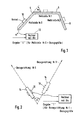
- the measuring points 0, 1, 2 are to be defined at which the gyroscope used for the measurement can be used in a precisely reproducible manner.
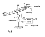
- the gyro 10 which emits a measurement signal ⁇ * for the respective measurement, is connected to a computer 12, which works with a time base. A reference value assigned to this point is entered into the computer for each measuring point.
- the reference quantity is a manually entered numbering of the measuring point or the reference direction with the numbers 0, 1, 2 etc., whereby the number 0 expresses that the angles to be measured relate to this measuring point (FIGS. 1 and 2) .
- the reference variable for the measuring point can of course also be automatically read into the computer by machine recognition Character or feature when touching down or running over.
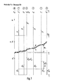
- the gyroscope is arranged in a stationary manner on the bending beam. In both cases, the force is the reference.
- the arrangement according to FIG. 6 shows the implementation of aerodynamic measurements for determining the lifting force 24 with the inflow angle ⁇ set in each case.
- the force is the reference variable.
- the repeated execution of measurements with the same reference values is regarded in the computer as a reference for angular equality, from which the possibility of determining the gyro measurement deviation which is active during the measurement process is described below due to unknown earth rate and gyro drift results with their subsequent correction. This is the decisive difference from the application of the support methods described above.
- the angle and angle characteristic measuring device does not need any external references during the measuring process, but only the information about the equality of reference values.
- the angle ⁇ * obtained by integration from the raw gyro measurements will be briefly referred to below as gyro measurement.
- the measuring program is important for data processing in the computer. It must be designed so that, when using a gyroscope, there is only one rotation around an axis, i.e. the angles to be measured lie in a reference plane fixed to the earth and the gyro measuring axis moves during the measurement not or only to a limited extent with respect to the solder at this reference level. On the other hand, measuring processes with the same reference values have to be repeated at least twice, whereby the conditions for the time differences between measurements explained below must also be observed.
- D ⁇ contains the unknown component of the earth rate plus gyro drift and R ⁇ its time changes.
- this is entered as the 3rd block. Inserted in Eq. (3), the gyro measurement can now be corrected at any time (Fig. 9, 4th block).
- the coefficients D ⁇ and R ⁇ should be determined on the basis of all possible differences ⁇ * i of the gyro measurements.
- the angle measuring device described above can also be used for this application without significant change.
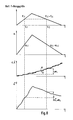
- the computer only needs to be informed that the forces or moments are now the reference values. Since the above-described procedure for processing the gyro measurement data is based on repeated measurements with the same reference values, the measurement program provides for a positive introduction of force or torque up to a maximum value, followed by a return to the initial value (Figs. 3, 4 and 8 ). In the case of aerodynamic measurements, the adjustment angle is used accordingly (FIGS. 6 and 8).
- the coefficient R ⁇ for the temporal change in the gyro drift which is sought for the gyro measurement deviation in the measurement equation (5), can only be determined by the computer if the measurement program considers as a condition for the temporal course of the measurements that (t i2 + t i1 ) also changes significantly.
- the time differences between the measurements in the positive adjustment range must then differ significantly from those in the negative.
- the positive adjustment speed can be chosen, for example, by a factor of 2 higher than the negative or vice versa (FIGS. 7 and 8).
- the scale factor calibration process uses the angle measurement method described above.
- An identifier for this operating mode is entered into the computer.
- the gyro to be calibrated is placed with its sensitive axis perpendicular to the surface and guided to the stop.
- the number 0 is entered into the computer as a reference.
- the gyroscope is now rotated on the surface by an angle of 360 ° and brought back to the stop, after which the number 1 is entered. Measurements after further adjustments in the alternating direction of rotation are marked with consecutive numbers.
- the computer determines the temporally variable measurement deviation as a result of earth rate and gyro drift, taking advantage of the fact that the proportion of a constant scale factor error has been reduced to zero in the gyro measurement after a positive and a negative 360 o rotation.
- the differences between measurements with even-numbered and odd-numbered numbers therefore only contain the above-mentioned gyro measurement deviation ⁇ (t).
- the corrected gyro angle measurements are available in the computer, which must be ⁇ 360 o after each rotation.
- the gyro scale factor error is to be determined from the difference and eliminated by correction.
Landscapes
- Physics & Mathematics (AREA)
- Engineering & Computer Science (AREA)
- General Physics & Mathematics (AREA)
- Radar, Positioning & Navigation (AREA)
- Remote Sensing (AREA)
- Life Sciences & Earth Sciences (AREA)
- Environmental & Geological Engineering (AREA)
- General Life Sciences & Earth Sciences (AREA)
- Geology (AREA)
- Aviation & Aerospace Engineering (AREA)
- Gyroscopes (AREA)
- Length Measuring Devices With Unspecified Measuring Means (AREA)
Applications Claiming Priority (4)
| Application Number | Priority Date | Filing Date | Title |
|---|---|---|---|
| DE4015800 | 1990-05-14 | ||
| DE19904015800 DE4015800A1 (de) | 1990-05-14 | 1990-05-14 | Verfahren zur messung von winkeln und winkelkennlinien mit hilfe eines kreisels |
| DE4021793 | 1990-07-09 | ||
| DE4021793A DE4021793A1 (de) | 1990-05-14 | 1990-07-09 | Verfahren zur messung von winkeln und winkelkennlinien mit hilfe eines kreisels |
Publications (3)
| Publication Number | Publication Date |
|---|---|
| EP0457200A2 true EP0457200A2 (fr) | 1991-11-21 |
| EP0457200A3 EP0457200A3 (en) | 1992-09-30 |
| EP0457200B1 EP0457200B1 (fr) | 1994-09-21 |
Family
ID=25893279
Family Applications (1)
| Application Number | Title | Priority Date | Filing Date |
|---|---|---|---|
| EP91107567A Expired - Lifetime EP0457200B1 (fr) | 1990-05-14 | 1991-05-09 | Méthode pour la mesure des angles et des caractéristiques d'angles utilisant un gyroscope |
Country Status (4)
| Country | Link |
|---|---|
| US (1) | US5283754A (fr) |
| EP (1) | EP0457200B1 (fr) |
| JP (1) | JPH0827192B2 (fr) |
| DE (2) | DE4021793A1 (fr) |
Cited By (2)
| Publication number | Priority date | Publication date | Assignee | Title |
|---|---|---|---|---|
| FR2667143A1 (fr) * | 1990-09-14 | 1992-03-27 | Deutsche Forsch Luft Raumfahrt | Procede pour le mesurage d'angles, de trajectoires, de contours et d'anomalies de gravite au moyen de gyroscopes et de systemes inertiels. |
| DE102006005258A1 (de) * | 2006-02-02 | 2007-08-16 | Litef Gmbh | Verfahren zur Ermittlung von Belastungen/Schäden einer mechanischen Struktur |
Families Citing this family (9)
| Publication number | Priority date | Publication date | Assignee | Title |
|---|---|---|---|---|
| DE4205869A1 (de) * | 1992-02-26 | 1993-09-02 | Teldix Gmbh | Einrichtung zur bestimmung der relativen orientierung eines koerpers |
| US5531115A (en) * | 1995-06-29 | 1996-07-02 | Erdley; Harold F. | Self-calibrating three axis angular rate sensor |
| US5596861A (en) * | 1995-10-24 | 1997-01-28 | Preston; Charles E. | System and method for establishing an absolute reference point for an envelope inserter cycle |
| DE29522352U1 (de) | 1995-12-12 | 2002-07-18 | Prüftechnik Dieter Busch AG, 85737 Ismaning | Lagemeßsonde zum gegenseitigen Ausrichten von Körpern |
| FR2756375B1 (fr) * | 1996-11-22 | 1999-01-22 | Sagem | Procede et dispositif de mesure d'inclinaison d'un axe lie a un porteur |
| DE19918140A1 (de) * | 1999-04-01 | 2000-10-12 | Deutsch Zentr Luft & Raumfahrt | Meßanordnung zur Regelung von Robotern, Werkzeugmaschinen und dergleichen sowie ein mit dieser Meßanordnung durchgeführtes Meßverfahren |
| FR2991048A1 (fr) * | 2012-05-22 | 2013-11-29 | Fbco | Diagnostic non destructif, determination des caracteristiques des ouvrages par enregistrement et decodage du comportement sous un spectre de sollicitations choisi ou impose |
| IL237971A (en) * | 2015-03-26 | 2016-10-31 | Gandelsman Mark | A device and method for determining relative orientation between two different locations |
| CN114894074B (zh) * | 2022-03-31 | 2023-08-08 | 中冶(上海)钢结构科技有限公司 | 用于快速测量超大截面压环梁索耳相对角度偏差的方法 |
Family Cites Families (9)
| Publication number | Priority date | Publication date | Assignee | Title |
|---|---|---|---|---|
| US3442140A (en) * | 1964-12-24 | 1969-05-06 | North American Rockwell | Drift rate compensation for acceleration sensitivity of an inertial navigation platform |
| US4151656A (en) * | 1977-09-12 | 1979-05-01 | Eastman Kodak Company | Manually manipulatable gyroscope-stabilized indicating apparatus and method for its use |
| US4143467A (en) * | 1978-05-01 | 1979-03-13 | Sperry Rand Corporation | Semi-automatic self-contained magnetic azimuth detector calibration apparatus and method |
| US4343035A (en) * | 1980-04-14 | 1982-08-03 | Tanner Walter E | Heading reference system |
| DE3111130A1 (de) * | 1981-03-21 | 1982-09-30 | Teldix Gmbh, 6900 Heidelberg | Betriebsverfahren fuer eine fahrzeugnavigationseinrichtung und anordnungen zur durchfuehrung des verfahrens |
| US4504146A (en) * | 1981-07-06 | 1985-03-12 | Honeywell Inc. | Ring laser gyro system |
| GB2103793B (en) * | 1981-08-20 | 1985-10-30 | Sperry Sun Inc | Instrument for monitoring the direction of a borehole |
| US4799391A (en) * | 1986-12-18 | 1989-01-24 | Atlantic Richfield Company | Method for surveying fluid transmission pipelines |
| WO1988009913A1 (fr) * | 1987-06-12 | 1988-12-15 | Osmond Beissbarth | Procede et dispositif de mesure de la position des roues |
-
1990
- 1990-07-09 DE DE4021793A patent/DE4021793A1/de not_active Withdrawn
-
1991
- 1991-05-09 DE DE59102998T patent/DE59102998D1/de not_active Expired - Fee Related
- 1991-05-09 EP EP91107567A patent/EP0457200B1/fr not_active Expired - Lifetime
- 1991-05-13 US US07/699,481 patent/US5283754A/en not_active Expired - Fee Related
- 1991-05-14 JP JP3107930A patent/JPH0827192B2/ja not_active Expired - Lifetime
Cited By (5)
| Publication number | Priority date | Publication date | Assignee | Title |
|---|---|---|---|---|
| FR2667143A1 (fr) * | 1990-09-14 | 1992-03-27 | Deutsche Forsch Luft Raumfahrt | Procede pour le mesurage d'angles, de trajectoires, de contours et d'anomalies de gravite au moyen de gyroscopes et de systemes inertiels. |
| DE102006005258A1 (de) * | 2006-02-02 | 2007-08-16 | Litef Gmbh | Verfahren zur Ermittlung von Belastungen/Schäden einer mechanischen Struktur |
| CN101379380B (zh) * | 2006-02-02 | 2010-12-01 | 诺思路格鲁曼利特夫有限责任公司 | 确定机械结构载荷/损坏的方法 |
| DE102006005258B4 (de) * | 2006-02-02 | 2011-01-20 | Litef Gmbh | Verfahren zur Ermittlung von Belastungen/Schäden einer mechanischen Struktur |
| US8830477B2 (en) | 2006-02-02 | 2014-09-09 | Northrop Grumman Litef Gmbh | Method for determining loads on a mechanical structure and the resultant damage |
Also Published As
| Publication number | Publication date |
|---|---|
| EP0457200A3 (en) | 1992-09-30 |
| JPH0827192B2 (ja) | 1996-03-21 |
| DE4021793A1 (de) | 1992-02-06 |
| EP0457200B1 (fr) | 1994-09-21 |
| DE59102998D1 (de) | 1994-10-27 |
| JPH04231813A (ja) | 1992-08-20 |
| US5283754A (en) | 1994-02-01 |
Similar Documents
| Publication | Publication Date | Title |
|---|---|---|
| DE4029215C2 (fr) | ||
| DE69314219T2 (de) | Vorrichtung zur Detektion des Fahrzeugkurses | |
| DE10001813C2 (de) | Meßsystem zur Ermittlung von Luftdaten eines Luftfahrzeuges sowie ein Verfahren zur Bestimmung der Luftdaten | |
| EP0557591B1 (fr) | Dispositif pour déterminer l'orientation relative d'un corps | |
| DE60315050T2 (de) | Vorrichtung und verfahren zur messung, kompensation und prüfung eines numerisch gesteuerten werkzeugskopfes und/oder tisches | |
| DE3418081C2 (fr) | ||
| EP2108105B1 (fr) | Procédé de détermination d'une grandeur d'influence sur l'excentricité dans un dispositif de mesure d'angle | |
| EP1279003B1 (fr) | Procede de determination de position et appareil de navigation | |
| DE19858621A1 (de) | Verfahren zum Verbessern der Meßwerte eines inertialen Meßsystems | |
| EP0457200B1 (fr) | Méthode pour la mesure des angles et des caractéristiques d'angles utilisant un gyroscope | |
| DE4034965A1 (de) | System zur messung der fahrtrichtung eines fahrzeugs | |
| EP0186666A1 (fr) | Procede pour determiner la direction de la marche d'un vehicule a l'aide d'un compas electronique. | |
| DE4000781C2 (de) | Verfahren zur Messung der Fahrtrichtung eines Fahrzeugs | |
| DE69416386T2 (de) | System zur Messung dreidimensionaler Verschiebungen | |
| DE4015800C2 (fr) | ||
| EP2581748B1 (fr) | Procédé et dispositif de détermination de grandeurs de mesure d'inertie | |
| EP0468193B1 (fr) | Procédé pour déterminer le nord | |
| DE19636425C1 (de) | Verfahren zur Navigation unter Verwendung unterschiedlicher Meßmethoden | |
| DE2631041A1 (de) | Verfahren und vorrichtung zur abstandsmessung | |
| DE4333032A1 (de) | Vorrichtung zur Bestimmung der Lage und Ausrichtung einer Tunnelvortriebsmaschine | |
| DE3637027A1 (de) | Verfahren zur berechnung des kipp- bzw. rollwinkels eines luftfahrzeugs und schleife zur durchfuehrung des verfahrens | |
| EP1440289B1 (fr) | Systeme de navigation destine a determiner la trajectoire d'un vehicule | |
| EP0247367A1 (fr) | Procédé pour régler une installation magnétique pour l'autoprotection servant à la compensation du champs magnétique perturbateur d'un véhicule, notamment un navire | |
| DE3828410A1 (de) | Verfahren zur verbesserung des nordungsergebnisses | |
| DE4205868A1 (de) | Verfahren und einrichtung zum kalibrieren einer messeinrichtung |
Legal Events
| Date | Code | Title | Description |
|---|---|---|---|
| PUAI | Public reference made under article 153(3) epc to a published international application that has entered the european phase |
Free format text: ORIGINAL CODE: 0009012 |
|
| AK | Designated contracting states |
Kind code of ref document: A2 Designated state(s): DE FR GB |
|
| PUAL | Search report despatched |
Free format text: ORIGINAL CODE: 0009013 |
|
| AK | Designated contracting states |
Kind code of ref document: A3 Designated state(s): DE FR GB |
|
| 17P | Request for examination filed |
Effective date: 19921002 |
|
| 17Q | First examination report despatched |
Effective date: 19931026 |
|
| GRAA | (expected) grant |
Free format text: ORIGINAL CODE: 0009210 |
|
| AK | Designated contracting states |
Kind code of ref document: B1 Designated state(s): DE FR GB |
|
| REF | Corresponds to: |
Ref document number: 59102998 Country of ref document: DE Date of ref document: 19941027 |
|
| ET | Fr: translation filed | ||
| GBT | Gb: translation of ep patent filed (gb section 77(6)(a)/1977) |
Effective date: 19941020 |
|
| PLBE | No opposition filed within time limit |
Free format text: ORIGINAL CODE: 0009261 |
|
| STAA | Information on the status of an ep patent application or granted ep patent |
Free format text: STATUS: NO OPPOSITION FILED WITHIN TIME LIMIT |
|
| 26N | No opposition filed | ||
| PGFP | Annual fee paid to national office [announced via postgrant information from national office to epo] |
Ref country code: DE Payment date: 20000426 Year of fee payment: 10 |
|
| PGFP | Annual fee paid to national office [announced via postgrant information from national office to epo] |
Ref country code: GB Payment date: 20000428 Year of fee payment: 10 |
|
| PGFP | Annual fee paid to national office [announced via postgrant information from national office to epo] |
Ref country code: FR Payment date: 20000517 Year of fee payment: 10 |
|
| PG25 | Lapsed in a contracting state [announced via postgrant information from national office to epo] |
Ref country code: GB Free format text: LAPSE BECAUSE OF NON-PAYMENT OF DUE FEES Effective date: 20010509 |
|
| GBPC | Gb: european patent ceased through non-payment of renewal fee |
Effective date: 20010509 |
|
| PG25 | Lapsed in a contracting state [announced via postgrant information from national office to epo] |
Ref country code: FR Free format text: LAPSE BECAUSE OF NON-PAYMENT OF DUE FEES Effective date: 20020131 |
|
| PG25 | Lapsed in a contracting state [announced via postgrant information from national office to epo] |
Ref country code: DE Free format text: LAPSE BECAUSE OF NON-PAYMENT OF DUE FEES Effective date: 20020301 |