EP0457220A1 - Dispositifs de succion - Google Patents
Dispositifs de succion Download PDFInfo
- Publication number
- EP0457220A1 EP0457220A1 EP91107652A EP91107652A EP0457220A1 EP 0457220 A1 EP0457220 A1 EP 0457220A1 EP 91107652 A EP91107652 A EP 91107652A EP 91107652 A EP91107652 A EP 91107652A EP 0457220 A1 EP0457220 A1 EP 0457220A1
- Authority
- EP
- European Patent Office
- Prior art keywords
- suction
- bore
- conduit
- passage
- handle
- Prior art date
- Legal status (The legal status is an assumption and is not a legal conclusion. Google has not performed a legal analysis and makes no representation as to the accuracy of the status listed.)
- Granted
Links
- 238000011144 upstream manufacturing Methods 0.000 claims abstract description 5
- 230000001419 dependent effect Effects 0.000 claims 1
- 230000000063 preceeding effect Effects 0.000 claims 1
- 239000000523 sample Substances 0.000 abstract description 28
- 230000004048 modification Effects 0.000 abstract description 4
- 238000012986 modification Methods 0.000 abstract description 4
- 239000002991 molded plastic Substances 0.000 abstract 1
- 239000002699 waste material Substances 0.000 description 12
- 239000000463 material Substances 0.000 description 6
- 238000002347 injection Methods 0.000 description 2
- 239000007924 injection Substances 0.000 description 2
- 229920003023 plastic Polymers 0.000 description 2
- 239000004033 plastic Substances 0.000 description 2
- 238000011084 recovery Methods 0.000 description 2
- 210000001015 abdomen Anatomy 0.000 description 1
- NIXOWILDQLNWCW-UHFFFAOYSA-N acrylic acid group Chemical group C(C=C)(=O)O NIXOWILDQLNWCW-UHFFFAOYSA-N 0.000 description 1
- 230000004323 axial length Effects 0.000 description 1
- 239000008280 blood Substances 0.000 description 1
- 210000004369 blood Anatomy 0.000 description 1
- 210000001124 body fluid Anatomy 0.000 description 1
- 239000010839 body fluid Substances 0.000 description 1
- 210000000988 bone and bone Anatomy 0.000 description 1
- 238000004040 coloring Methods 0.000 description 1
- 230000000295 complement effect Effects 0.000 description 1
- 239000012530 fluid Substances 0.000 description 1
- 230000007794 irritation Effects 0.000 description 1
- 238000004519 manufacturing process Methods 0.000 description 1
- 239000002184 metal Substances 0.000 description 1
- 230000001338 necrotic effect Effects 0.000 description 1
- 239000002245 particle Substances 0.000 description 1
- 210000003800 pharynx Anatomy 0.000 description 1
- 210000001519 tissue Anatomy 0.000 description 1
Images
Classifications
-
- A—HUMAN NECESSITIES
- A61—MEDICAL OR VETERINARY SCIENCE; HYGIENE
- A61C—DENTISTRY; APPARATUS OR METHODS FOR ORAL OR DENTAL HYGIENE
- A61C17/00—Devices for cleaning, polishing, rinsing or drying teeth, teeth cavities or prostheses; Saliva removers; Dental appliances for receiving spittle
- A61C17/06—Saliva removers; Accessories therefor
- A61C17/08—Aspiration nozzles
-
- A—HUMAN NECESSITIES
- A61—MEDICAL OR VETERINARY SCIENCE; HYGIENE
- A61M—DEVICES FOR INTRODUCING MEDIA INTO, OR ONTO, THE BODY; DEVICES FOR TRANSDUCING BODY MEDIA OR FOR TAKING MEDIA FROM THE BODY; DEVICES FOR PRODUCING OR ENDING SLEEP OR STUPOR
- A61M1/00—Suction or pumping devices for medical purposes; Devices for carrying-off, for treatment of, or for carrying-over, body-liquids; Drainage systems
- A61M1/71—Suction drainage systems
- A61M1/74—Suction control
- A61M1/741—Suction control with means for varying suction manually
- A61M1/7411—Suction control with means for varying suction manually by changing the size of a vent
-
- A—HUMAN NECESSITIES
- A61—MEDICAL OR VETERINARY SCIENCE; HYGIENE
- A61M—DEVICES FOR INTRODUCING MEDIA INTO, OR ONTO, THE BODY; DEVICES FOR TRANSDUCING BODY MEDIA OR FOR TAKING MEDIA FROM THE BODY; DEVICES FOR PRODUCING OR ENDING SLEEP OR STUPOR
- A61M1/00—Suction or pumping devices for medical purposes; Devices for carrying-off, for treatment of, or for carrying-over, body-liquids; Drainage systems
- A61M1/84—Drainage tubes; Aspiration tips
- A61M1/86—Connectors between drainage tube and handpiece, e.g. drainage tubes detachable from handpiece
-
- Y—GENERAL TAGGING OF NEW TECHNOLOGICAL DEVELOPMENTS; GENERAL TAGGING OF CROSS-SECTIONAL TECHNOLOGIES SPANNING OVER SEVERAL SECTIONS OF THE IPC; TECHNICAL SUBJECTS COVERED BY FORMER USPC CROSS-REFERENCE ART COLLECTIONS [XRACs] AND DIGESTS
- Y10—TECHNICAL SUBJECTS COVERED BY FORMER USPC
- Y10S—TECHNICAL SUBJECTS COVERED BY FORMER USPC CROSS-REFERENCE ART COLLECTIONS [XRACs] AND DIGESTS
- Y10S285/00—Pipe joints or couplings
- Y10S285/924—Vented
-
- Y—GENERAL TAGGING OF NEW TECHNOLOGICAL DEVELOPMENTS; GENERAL TAGGING OF CROSS-SECTIONAL TECHNOLOGIES SPANNING OVER SEVERAL SECTIONS OF THE IPC; TECHNICAL SUBJECTS COVERED BY FORMER USPC CROSS-REFERENCE ART COLLECTIONS [XRACs] AND DIGESTS
- Y10—TECHNICAL SUBJECTS COVERED BY FORMER USPC
- Y10S—TECHNICAL SUBJECTS COVERED BY FORMER USPC CROSS-REFERENCE ART COLLECTIONS [XRACs] AND DIGESTS
- Y10S604/00—Surgery
- Y10S604/902—Suction wands
Definitions
- This invention relates to suction devices and in particular such devices for medical, surgical or dental use.
- Suction devices are used for medical, surgical or dental use to remove foreign matter, fluid, blood, pus, mucous, polyps, bone particles, necrotic and cancerous matter and the like (all of which are hereinafter referred to as "waste matter").
- Such suction devices are normally provided in two types viz a suction nozzle comprising a rigid nozzle or a suction catheter comprising an elongated flexible catheter which can be inserted into the body as desired.
- the nozzle or catheter is normally connected to a suction source via an intermediate member which is connected by connection means to a flexible tube that is connected to the suction source, the connection means being normally in the form of a hollow spigot.
- the intermediate member may comprise a handle that may be integral with the probe.
- a suction port may be provided in the intermediate member leading to the suction passage therethrough and the medical personnel operating the suction device, by obturating the suction port to a greater or lesser extent, can vary the suction at the tip of the probe.
- a suction device comprising a suction member having an internal suction passage terminating at a suction tip at the distal end thereof; and an intermediate member having a connection part for connection to a source of suction, a suction bore that is connectable to the suction passage, to form a suction line through the device, and a controllable suction port and a conduit which is narrow in one dimension, usually no more than 3mm and preferably about 1mm, and which connects the suction port to the suction line.
- the conduit may have its other dimensions being quite large so that its flow area is adequate to permit sufficient air flow therethrough when the suction port is open so that there will be no or very little suction at the tip of the suction member.
- the conduit preferably connects to the suction passage downstream of its connection to the suction port i.e. when the suction port is open there will be air movement in the conduit in the same direction as the movement in the suction passage through the intermediate member.
- the suction member has an end part entering the suction bore and defining therewith the said conduit.
- the end part is preferably a tubular end member that is received in coaxial spaced relationship in the suction bore so as to form an annular conduit between the end part and the bore.
- the suction member is preferably separate from the intermediate member and preferably has a hollow spigot that fits within a reception bore in the intermediate member in such a way that the conduit is formed between the spigot and the bore, the conduit preferably being of annular cross-section.
- the reception bore may form part of the suction passage through the intermediate member.
- the reception bore is conveniently of larger diameter than the suction passage, there being connection opening means between the conduit and the suction passage which opening means also has one dimension that is very small.
- the suction member may comprise a flexible catheter connected to the intermediate member in which case a union is preferably provided on the catheter connecting it to the intermediate member.
- the suction member and the intermediate member are preferably capable of being separated from one another and conveniently the intermediate member has a forward opening provided with internal screw threads and the suction member has a part formed with external screw threads engage the internal screw threads.
- engaging means are provided on the suction and intermediate members which limit the relative members to rotation thereof.
- the free end of the cylindrical end member may be cut off at an incline to the axis thereof.
- the end part may comprise a shield that butts against the suction bore to define therewith the conduit.
- the end of the suction member closer to the intermediate member may have a thickened wall and the controllable suction port is formed in such wall.
- the conduit in this arrangement may includes a plenum chamber also formed in said thickened wall.
- the intermediate member may have a second passage running parallel with a suction bore and having the suction port formed at one end thereof wherein the second passage is connected to the suction bore by the conduit which is preferably connected to the suction bore downstream of the location of the connection between the conduit and the second passage.
- the conduit preferably extends parallel to suction bore.
- the nozzle and the handle preferably comprise different materials.
- probe is provided with a spigot entering a reception bore in the handle, there being an annular or part annular conduit being formed between the spigot and the handle which prevents waste matter moving to the suction port.
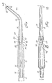
- the nozzle 10 comprises a hollow handle 12 having a suction bore 14 running along its length. At its rear end, the handle 12 has an integral spigot 16 formed thereon through which, the suction bore 14 passes.
- This spigot 16 is generally frusto-conical in shape so as to be able to be received within a flexible suction tube (indicated in chain lines at 17) connected to a hospital's suction apparatus.
- the handle 12 At its front end, the handle 12 is connected to a hollow elongated rigid probe 18 having a suction passage 20 therethrough. At its forward or distal end, the probe 18 ends in a tip 22 with suitable suction openings 24 leading into the passage 20.
- the handle 12 comprises an injection moulded ABS (acrilonitrile-butadiene-styrene) member containing colouring matter to make it opaque.
- the probe 18 is an injection moulded, substantially transparent acrylic member. The precise materials to be used will be apparant to any moulder skilled in the art. I have found that these parts engage and disengage easily and smoothly.
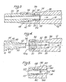
- the front end of the handle 12 has an enlarged reception bore 26 (best shown in Figures 4 and 5) that is coaxial with the suction bore 14 and has a base 28 lying in a plane radial to the axis 26 a of the reception bore.
- the diameter of the bore 26 is 10mm.
- the bore 26 leads to an enlarged entrance section 30 to which it is connected by a frusto-conical part 32.
- the entrance section 30 has internal square section threads 34 formed therein.
- Above the bore 26 there is a shallow finger depression 36 formed in the outer surface of the handle.
- a four millimetre diameter port 38 at the end of a radial passage 39 is provided at the lowest portion of the finger depression.
- Finger grip depressions 40 are provided on either side of depression 36.
- the proximal or rear end of the probe 18 is provided with a spigot 42, there being a radial shoulder 44 between the probe 18 and the spigot.
- the spigot 42 has a short externally threaded cylindrical portion 46 which has a square section thread 48 formed thereon to fit threadedly into the threads 34 in the reception bore 26.
- the thread 48 extends through 540° (five hundred and forty degrees).
- the spigot 42 has a frusto-conical section 50 beyond the threaded portion 48 which is complementary to the portion 32 of the bore 26 and lies flush thereagainst to limit the inward movement of the spigot 42 into the bore 26 and also to seal thereagainst.
- the end of the section 50 is stepped down to a cylindrical end portion 52 of reduced external diameter which is two millimetres smaller than the diameter of the bore 26.
- the end portion 52 lies in spaced co-axial relationship within the reception bore 26 so that there is an annular space or conduit 54 between the end 50 and the bore 26.
- the end face 56 of the spigot 42 is located about one millimetre short of the shoulder 28 between the reception bore 26 and the suction bore 14 and closer to the rear end of the bore 14.
- the cross-sectional area of the annular space 54 is 28,28mm2 and the radial width is one millimetre.
- the cross-sectional area of the opening 58 (which is cylindrical in shape) is also substantial (29,13mm2) while the narrowest dimension, i.e. the axial length of the opening (1mm), is small.
- the axis of the port 38 joins the annular space 54 five millimetres behind the end face 56 of the spigot 42.
- the probe 18 is inserted into the handle 12 by placing the spigot 42 into the bore 26 with the probe 18 located at a position 180° from its normal working position.
- the threads 48 engage in the female threads 34 and the probe 18 is rotated through 540° (i.e. one and a half turns) until it reaches its desired operating position. Further movement of the spigot is prevented by engagement of the frusto-conical surfaces 50 and 32 and by the shoulder 44 of the probe 18 butting against the front end 12 a of the handle.
- suction nozzle 10 When suction is applied to the suction nozzle, air is drawn into suction passage 14 both from the nozzle tip and the suction port 38. When the suction port 38 is open there will be little or no suction at the nozzle tip. As the suction port 38 is obturated to a greater degree by the anaesthetist's finger, the suction at the tip will be increased and of course when the suction port 38 is wholly obturated, the full suction will be applied at the nozzle tip.
- the controllable suction nozzle 10 can be manipulated in conventional manner by an anaesthetist into the mouth or pharynx of a patient so that the suction can be applied to matter to be removed therefrom.
- the suction nozzle 10 operates effectively and well. Furthermore because the connection between the annular conduit 54 to the passage 14 is upstream of opening 56, waste material will not migrate to the port 38. I believe that because of the enlargement of the flow passage at the opening 58, increased suction will be caused - through the conduit 54. This will provide inter alia improved clearing of conduit 54 when the nozzle is connected to suction and the suction port 38 is at least partially open. I believe that the annular conduit 54 also serves as a plenum chamber which also serves to prevent movement of the waste material to the suction port 38. Indeed the air flow through the conduit 58 will move such matter away from the suction port 38 which will normally if not always remain clean in use.
- the suction nozzle 10 is formed in two parts, the mould in which the parts are made can be of significantly less size, as can be the mould insert(s), and consequently is less costly than the moulds for conventional suction nozzles. These nozzles 10 thus can be disposable.
- the probes can be of varying shapes and sizes and tip configurations can be mounted on a handle of one shape, thus reducing still further the costs of manufacture while permitting the anaesthetist considerable scope in the choice of probe to be used.
- the suction noise of the nozzle 10 is much lower than that of conventional suction nozzles. This noise can barely be heard against the noises in the operating theatre and does not cause irritation and distraction in the operating theatre. It is thought that the end member 50 on the spigot 42 serves as a baffle which reduces noise as aforesaid.
- the modified nozzle shown in Figure 5 is generally similar to the embodiment of Figures 1 to 4 (and wherein the reference numbers for identical parts are the same with the addition of 100 to the numbers) save that the end 156 of the spigot 142 is provided with castellations 160 which engage the base 128 of the reception bore 126.
- the opening 158 is formed by a plurality of ports 162 between the castellations 160.
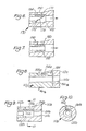
- the nozzle 170 therein shown is substantially identical to the nozzle 10 save that the end member 172 has its front face 176 cut on an incline.
- the passage 178 from the suction port 180 enters the reception bore 182 upstream of the end of the longest portion of the end member which is located directly below the suction port 180 i.e. it enters into a narrow conduit 184 prior to being connected to the reception bore.
- the nozzle 186 has a reception bore 188 is of the same diameter as, and is a continuation of, the suction passage.
- the annular conduit 190 surrounding the end part 192 of the spigot enters into the suction passage through an annular opening without a further change of direction of the air passing therethrough.
- the suction nozzle 110 a has a suction port 138 a that is formed in the proximal end of the probe 116 a which is at this end of relative great wall thickness.
- the nozzle 138 a connects to a narrow conduit 154 a of a few millimetres length and a minimum cross-sectional dimension of one millimetre formed in the wall of the probe 116 a .
- This conduit 154 a leads to a plenum chamber 194 of somewhat greater diameter that is also formed in the nozzle wall and that opens into an annular connecting port 156 a formed by an annular recess in the front face of the handle 112 a .
- This port 156 a connects with the suction bore 114 a .
- the connection between the probe 116 a and the handle112 may be effected as desired and is not illustrated herein.
- the suction nozzle 110 a operates in the same way as the embodiments described above.
- the provision of the plenum chamber 194 and the small conduit 154a prevents waste matter migrating to the suction port 138 a .
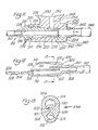
- the suction nozzle 110 b illustrated in Figures 9 and 10 is generally similar to the suction nozzle 10 save that the spigot does not have an annular end 50. Instead the spigot 142 b is provided with a chordal shield 151 b that seals against the walls of the reception bore 126 b (as best shown in Figure 10) to leave an elongated passage 154 b whose radial dimension is small. This passage 154 b connects with the suction port 114 b through a narrow opening 158 b that is located downstream of the suction port 138 b .
- the suction nozzle 110 b operates in the same manner as the embodiments described above.
- the provision of the small conduit 154 b prevents waste matter migrating to the suction port 138 b and contaminating the aneasthetist's finger.
- the device 210 comprises a flexible catheter 212 that extends any desired length and terminates in a suction tip (not shown) at its distal end.
- a connector or union 214 is attached to the proximal end of the catheter.
- the union 214 includes a front spigot 216, a flange 218 leading to a cylindrical body 220 having a frustoconical section 222 that terminates in a smaller end spigot 224.
- Male threads 226 are provided on the body 220.
- a suction passage 228 connected to the bore 230 of the catheter 212 extends through the union 214.
- the union 212 fits into the front end of an intermediate member 232 which has an entrance bore 234 provided with internal threads 235 and leading via a frusto-conical part 236 to a reception bore 238.
- the reception bore 238 has a flat base 240 into which opens a suction passage 242 of smaller dimensions.
- the intermediate member 232 terminates in a spigot 244 which fits into the theatre suction pipe 246.
- a radial boss 248 extends from the central portion of the intermediate member 232 and has at its upper end a finger rest 250.
- a suction port 252 is provided in the finger rest leading to a short bore 254 that extends radially of and into the reception bore 238.
- the union 214 fits the front end of the intermediate member.
- the body 220 fits the entrance bore 234 with the male threads 226 engaging the internal threads 235.
- the frusto-conical section 222 butts and seals against the frusto-conical part 236 of the bore and the end spigot 224 is coaxially received within the reception bore 238 in such a way that there is an annular conduit 256 therebetween.
- the end face 258 of the end spigot 224 is spaced slightly from the base 240 of the reception bore 238.
- the bore 254 enters the conduit 256 upstream of the opening 260.
- FIG. 12 wherein is shown a suction catheter 300 including an intermediate member or handle 302 and a flexible catheter 304 having a tip 306 at its distal end formed with suitable ports 308.
- the handle 302 has a spigot 310 at its proximal end for connection to a tube 312 leading to the hospital suction device. Internally the handle 302 has upper and lower passages 314 and 316 separated by a longitudinally extending cross-piece 318 that terminates somewhat short of the spigot 310. The passage 316 receives a plastic union 319 in which the distal end of the catheter 304 is sealingly received.
- the distal end of the passage 314 has an inclined face 326 to provide a suction port that an anaesthetist can control with his finger to control the suction at the tip 306 of the catheter 304.
- a transverse somewhat arcuate shield 320 is formed integrally with the handle 302 and overlies the distal end of the cross-piece forming therewith a narrow conduit 322 that has a small vertical dimension and that extends in the direction of the handle for a few (about eight) millimetres.
- This conduit 322 connects together the passage 314 with the passage 316 and the suction bore 324 of the spigot 310 downstream from the suction port. It will be noted too that the passage 314 extends beyond the connection between the passage 314 and the conduit 322.
- Extra material is provided at either side of the handle 302 at 328 for improved rigidity.
- waste matter will not foul the suction port. Also the suction noises emitted by this device are minimal.
- the handle may be of any desired shape and size and the probe can be of any desired shape and size.
- the tip of the probe can be shaped or configured as desired.
- the connection between the probe and the handle can be varied as desired and indeed the probe can be permanently secured to the handle.
- Some or all of the finger depressions may be differently shaped or could be omitted.
- the probe and or the handle may comprise different materials with the probe being preferably transparent. Although the materials are preferably plastics materials, one or both of the parts can comprise metal.
- the arrangement with a catheter need not incorporate the boss and finger plate, the suction port being formed directly in the intermediate member.
- the nozzle may of course be used by medical personnel not only in the operating theatre but also in the recovery room or wheresoever medical draining or suction is required.
- the various dimensions given apply to the currently apparatus of the invention. However these dimensions may vary as required save that the narrow dimension of the conduit (54 etc) should be sufficient for the waste member to form a miniscus thereacross i.e. normally up to about 3 mm and preferably about 1 mm.
- the transverse shield in the catheter device 210 can be straight.
- the suctions devices can be put to other uses with or without such suitable modification for such purposes. Thus they may be used for sucking, removing or transfering matter in a controlled manner in industrial or laboratory conditions without the operator having his finger contaminated thereby.
Landscapes
- Health & Medical Sciences (AREA)
- Heart & Thoracic Surgery (AREA)
- Life Sciences & Earth Sciences (AREA)
- Veterinary Medicine (AREA)
- Public Health (AREA)
- General Health & Medical Sciences (AREA)
- Animal Behavior & Ethology (AREA)
- Anesthesiology (AREA)
- Hematology (AREA)
- Biomedical Technology (AREA)
- Engineering & Computer Science (AREA)
- Vascular Medicine (AREA)
- Dentistry (AREA)
- Epidemiology (AREA)
- Surgery (AREA)
- External Artificial Organs (AREA)
- Separation By Low-Temperature Treatments (AREA)
- Feeding, Discharge, Calcimining, Fusing, And Gas-Generation Devices (AREA)
Applications Claiming Priority (2)
| Application Number | Priority Date | Filing Date | Title |
|---|---|---|---|
| ZA903645 | 1990-05-14 | ||
| ZA903645 | 1990-05-14 |
Publications (2)
| Publication Number | Publication Date |
|---|---|
| EP0457220A1 true EP0457220A1 (fr) | 1991-11-21 |
| EP0457220B1 EP0457220B1 (fr) | 1995-05-24 |
Family
ID=25580106
Family Applications (1)
| Application Number | Title | Priority Date | Filing Date |
|---|---|---|---|
| EP91107652A Expired - Lifetime EP0457220B1 (fr) | 1990-05-14 | 1991-05-10 | Dispositifs de succion |
Country Status (7)
| Country | Link |
|---|---|
| US (1) | US5123840A (fr) |
| EP (1) | EP0457220B1 (fr) |
| JP (1) | JPH04231064A (fr) |
| AT (1) | ATE122902T1 (fr) |
| AU (1) | AU646666B2 (fr) |
| CA (1) | CA2042523C (fr) |
| DE (1) | DE69109932T2 (fr) |
Cited By (12)
| Publication number | Priority date | Publication date | Assignee | Title |
|---|---|---|---|---|
| EP0558846A1 (fr) * | 1992-02-26 | 1993-09-08 | Haruo Takase | Tube de succion pour opérations chirurgicales |
| EP0673263A4 (fr) * | 1992-12-11 | 1998-12-23 | American Hydro Surgical Instr | Dispositif d'accouplement a deconnexion rapide pour l'extremite de sonde d'un instrument de laparoscopie. |
| ES2128232A1 (es) * | 1996-03-13 | 1999-05-01 | Fernandez Manuel Sevillano | Separador de cerebro con aspiracion incorporada |
| EP1129735A3 (fr) * | 2000-03-01 | 2002-02-27 | Meddis Limited | Cathéter |
| EP1364665A1 (fr) * | 2002-05-22 | 2003-11-26 | Surgimark, Inc. | Dispositif d'emmanchement pour la fixation d'un manche sur l'extrémité d'un aspirateur chirurgical |
| US7125402B1 (en) * | 2002-05-29 | 2006-10-24 | Surgimark, Inc. | Surgical drain |
| WO2006131155A1 (fr) * | 2005-06-07 | 2006-12-14 | Unomedical A/S | Dispositif chirurgical d'aspiration et procede de fabrication |
| EP1752110A2 (fr) | 2005-08-13 | 2007-02-14 | Dürr-Dental GmbH & Co. KG | Adaptateur pour un système d'aspiration dentaire |
| EP1955672A1 (fr) | 2007-02-06 | 2008-08-13 | Dürr Dental GmbH & Co. KG | Canule d'aspiration pour un dispositif d'aspiration dentaire |
| US7776004B2 (en) | 2002-05-22 | 2010-08-17 | Surgimark, Inc. | Aspirator sleeve and suction handle |
| US10737001B2 (en) | 2016-07-20 | 2020-08-11 | Surgimark, Inc. | Aspirators, components thereof, and associated clearances |
| EP3714837A1 (fr) * | 2019-03-25 | 2020-09-30 | Coltène/Whaledent GmbH + Co. KG | Canule d'aspiration en deux pièces pour traitements médicaux dentaires |
Families Citing this family (70)
| Publication number | Priority date | Publication date | Assignee | Title |
|---|---|---|---|---|
| US5217465A (en) * | 1992-02-28 | 1993-06-08 | Alcon Surgical, Inc. | Flexible and steerable aspiration tip for microsurgery |
| US5250033A (en) * | 1992-10-28 | 1993-10-05 | Interventional Thermodynamics, Inc. | Peel-away introducer sheath having proximal fitting |
| US5425637A (en) * | 1994-03-31 | 1995-06-20 | 601976 Alebrta Ltd. | Method and apparatus for preventing a back flow of oral contaminants in a low volume suction line of a dental saliva ejector |
| US5554155A (en) * | 1994-06-03 | 1996-09-10 | Johns Hopkins University | Fiber optic pick manipulator |
| US5509802A (en) * | 1995-02-03 | 1996-04-23 | White Shield Inc. | Oral suction tip |
| AU5264296A (en) * | 1995-04-07 | 1996-10-23 | White Shield Inc. | Disposable oral suction tip |
| US5876384A (en) * | 1995-10-05 | 1999-03-02 | Dragan; William B. | Micro aspirator |
| US5882197A (en) * | 1995-11-27 | 1999-03-16 | Davis; Warren | Illuminated suction tool with disposable tip |
| US6129547A (en) | 1997-05-06 | 2000-10-10 | Ballard Medical Products | Oral care system |
| US6186422B1 (en) * | 1998-09-30 | 2001-02-13 | Air Techniques | Nozzle assembly for air abrasion system |
| US6083003A (en) * | 1998-10-23 | 2000-07-04 | Kwasnik; Robert J. | Electromagnetically actuated valve for hydraulic motor vehicle brake systems |
| US6406454B1 (en) | 2000-03-14 | 2002-06-18 | Mohammed Ali Hajianpour | Surgical suction probe system with an easily cleaned internal filter |
| US6908455B2 (en) | 2000-03-14 | 2005-06-21 | Mohammed Ali Hajianpour | Surgical suction probe system with an easily cleaned internal filter |
| FR2835585B1 (fr) * | 2002-02-04 | 2004-03-05 | Staubli Sa Ets | Raccord rapide pour la jonction amovible de deux canalisations |
| US8845672B2 (en) | 2002-05-09 | 2014-09-30 | Reshape Medical, Inc. | Balloon system and methods for treating obesity |
| US6875173B2 (en) * | 2003-01-17 | 2005-04-05 | Loubert Suddaby | Laminectomy suction and retraction device |
| CA2433107A1 (fr) | 2003-06-30 | 2004-12-30 | Patrick D. Lemoine | Dispositif casse-vide a faible bruit et appareil d'aspiration reglable utilisant ce dispositif |
| DE102004049509B4 (de) * | 2004-10-11 | 2009-05-14 | Hirte, Liane, Dr. | Speichelsauger |
| US20060200085A1 (en) * | 2005-02-15 | 2006-09-07 | Philip Watts | Tissue transfer cannula and connectors |
| US20070016136A1 (en) * | 2005-05-18 | 2007-01-18 | Opie John C | Suction hand-piece device with variable control off/on valve |
| WO2007005902A2 (fr) * | 2005-07-01 | 2007-01-11 | Bio-Matrix Scientific Group Inc. | Dispositif de serrage de seringue |
| WO2007038433A2 (fr) * | 2005-09-23 | 2007-04-05 | Bio-Matrix Scientific Group Inc. | Manche et systeme de rangement de canule |
| US20070100368A1 (en) | 2005-10-31 | 2007-05-03 | Quijano Rodolfo C | Intragastric space filler |
| US20070225636A1 (en) * | 2006-03-21 | 2007-09-27 | Michael Hahn | Surgical suction device |
| DE102006016211A1 (de) * | 2006-04-03 | 2007-10-04 | Novalung Gmbh | Kupplung für rohrförmige Elemente |
| US8226602B2 (en) * | 2007-03-30 | 2012-07-24 | Reshape Medical, Inc. | Intragastric balloon system and therapeutic processes and products |
| US8070189B2 (en) | 2007-06-20 | 2011-12-06 | Carefusion 303, Inc. | Safety luer connection |
| US8142469B2 (en) * | 2007-06-25 | 2012-03-27 | Reshape Medical, Inc. | Gastric space filler device, delivery system, and related methods |
| US7984934B1 (en) | 2008-09-08 | 2011-07-26 | Blaton David J | Brazing of a special gas delivery system using fittings having purge orifices |
| US9174031B2 (en) * | 2009-03-13 | 2015-11-03 | Reshape Medical, Inc. | Device and method for deflation and removal of implantable and inflatable devices |
| CA2757547A1 (fr) * | 2009-04-03 | 2010-10-07 | Reshape Medical, Inc. | Charges ameliorees de l'espace intragastrique et procedes de preparation, comprenant des tests in vitro |
| EP2456507A4 (fr) | 2009-07-22 | 2013-07-03 | Reshape Medical Inc | Mécanismes de retrait pour dispositifs médicaux implantables |
| EP2456487A4 (fr) | 2009-07-23 | 2017-05-17 | ReShape Medical, Inc. | Mécanismes de gonflage et de dégonflage pour dispositifs médicaux gonflables |
| WO2011011743A2 (fr) * | 2009-07-23 | 2011-01-27 | Reshape Medical, Inc. | Dégonflage et retrait de dispositif médicaux implantables |
| WO2011038270A2 (fr) | 2009-09-24 | 2011-03-31 | Reshape Medical, Inc. | Normalisation et stabilisation de surfaces de ballonnet pour dégonflement |
| EP2533845A4 (fr) | 2010-02-08 | 2016-04-06 | Reshape Medical Inc | Procédés et mécanismes d'aspiration améliorés et perfectionnés pour dispositifs intragastriques |
| EP2533846B1 (fr) | 2010-02-08 | 2018-08-22 | ReShape Medical LLC | Matériaux et procédés pour dispositifs améliorés à ballon intragastrique |
| EP2539011A4 (fr) | 2010-02-25 | 2014-03-26 | Reshape Medical Inc | Procédés d'explantation améliorés et perfectionnés et mécanismes pour dispositifs intragastriques |
| WO2011127205A1 (fr) | 2010-04-06 | 2011-10-13 | Reshape Medical , Inc. | Dispositifs de gonflage pour des dispositifs intragastriques à une fixation et un détachement améliorés et systèmes et procédés associés |
| EP2407103B1 (fr) * | 2010-07-14 | 2013-11-27 | General Electric Company | Connexion de fluide pour réduire le volume de fluide dans la connexion |
| USD683453S1 (en) * | 2012-02-21 | 2013-05-28 | Centrix, Inc. | Dental material dispensing tube |
| US20130164706A1 (en) * | 2011-12-23 | 2013-06-27 | Gsn Products, Inc. | Adjustable suction tips for dental and medical uses |
| USD704024S1 (en) * | 2012-07-10 | 2014-05-06 | 3M Innovative Properties Company | Handle |
| USD704025S1 (en) * | 2012-11-21 | 2014-05-06 | 3M Innovative Properties Company | Handle |
| US9248228B2 (en) | 2013-01-18 | 2016-02-02 | Peter L. Bono | Suction and irrigation apparatus with anti-clogging capability |
| US9713563B2 (en) * | 2013-03-15 | 2017-07-25 | Compression Therapy Concepts, Inc. | Micro bleed hole connector for use in intermittent pneumatic compression devices |
| US10285720B2 (en) | 2014-03-11 | 2019-05-14 | Neuravi Limited | Clot retrieval system for removing occlusive clot from a blood vessel |
| ES2989493T3 (es) | 2014-06-13 | 2024-11-26 | Neuravi Ltd | Dispositivos para eliminar las obstrucciones agudas de los vasos sanguíneos |
| US10792056B2 (en) | 2014-06-13 | 2020-10-06 | Neuravi Limited | Devices and methods for removal of acute blockages from blood vessels |
| US10265086B2 (en) | 2014-06-30 | 2019-04-23 | Neuravi Limited | System for removing a clot from a blood vessel |
| US10463417B2 (en) * | 2014-09-17 | 2019-11-05 | Medtronic Cryocath Lp | Universal adaptor for gas scavenging systems |
| JP6579658B2 (ja) * | 2016-01-19 | 2019-09-25 | ニプロ株式会社 | 吸引ブラシ |
| CN107303398A (zh) * | 2016-04-17 | 2017-10-31 | 周星 | 防溢液口腔护理吸痰管 |
| EP3782562A1 (fr) | 2016-08-17 | 2021-02-24 | Neuravi Limited | Dispositif de récupération de caillot pour éliminer un caillot d'occlusion dans un vaisseau sanguin |
| EP4000540B1 (fr) | 2019-03-04 | 2024-02-14 | Neuravi Limited | Cathéter de récupération de caillot actionné |
| ES2987037T3 (es) | 2019-09-11 | 2024-11-13 | Neuravi Ltd | Catéter bucal expansible |
| US11779364B2 (en) | 2019-11-27 | 2023-10-10 | Neuravi Limited | Actuated expandable mouth thrombectomy catheter |
| US11839725B2 (en) | 2019-11-27 | 2023-12-12 | Neuravi Limited | Clot retrieval device with outer sheath and inner catheter |
| US12539130B2 (en) | 2019-11-27 | 2026-02-03 | Neuravi Limited | Aspiration catheter, systems, and methods thereof |
| US11944327B2 (en) | 2020-03-05 | 2024-04-02 | Neuravi Limited | Expandable mouth aspirating clot retrieval catheter |
| US11633198B2 (en) | 2020-03-05 | 2023-04-25 | Neuravi Limited | Catheter proximal joint |
| US11883043B2 (en) | 2020-03-31 | 2024-01-30 | DePuy Synthes Products, Inc. | Catheter funnel extension |
| US11759217B2 (en) | 2020-04-07 | 2023-09-19 | Neuravi Limited | Catheter tubular support |
| US20210338395A1 (en) * | 2020-05-04 | 2021-11-04 | Stoma Ventures, LLC | Disposable dental aerosol device |
| US20220257356A1 (en) * | 2021-02-12 | 2022-08-18 | M.N. Parchewsky Professional Corporation | Evacuation Apparatus and Method |
| US11872354B2 (en) | 2021-02-24 | 2024-01-16 | Neuravi Limited | Flexible catheter shaft frame with seam |
| US11937839B2 (en) | 2021-09-28 | 2024-03-26 | Neuravi Limited | Catheter with electrically actuated expandable mouth |
| US12011186B2 (en) | 2021-10-28 | 2024-06-18 | Neuravi Limited | Bevel tip expandable mouth catheter with reinforcing ring |
| US12521216B2 (en) * | 2021-11-12 | 2026-01-13 | Stoma Ventures, Llc. | Connector for a dental valve |
| CN117100367B (zh) * | 2023-08-22 | 2024-04-26 | 阜阳市人民医院 | 一种基于3d打印的脑出血穿刺引流装置及其制作方法 |
Citations (4)
| Publication number | Priority date | Publication date | Assignee | Title |
|---|---|---|---|---|
| DE1566561B (de) * | Aesculap Werke AG vorm Jetter & Scheerer, 7200 Tutthngen | Druckeinstellvornchtung für medizi nische Sauginstrumente | ||
| US3610242A (en) * | 1969-02-28 | 1971-10-05 | David S Sheridan | Medico-surgical suction systems |
| US3828780A (en) * | 1973-03-26 | 1974-08-13 | Valleylab Inc | Combined electrocoagulator-suction instrument |
| US4536180A (en) * | 1983-07-22 | 1985-08-20 | Johnson Gerald W | Surgical instrument for suction lipolysis |
Family Cites Families (11)
| Publication number | Priority date | Publication date | Assignee | Title |
|---|---|---|---|---|
| US2531730A (en) * | 1948-09-01 | 1950-11-28 | Gomco Surgical Mfg Corp | Surgical aspirator |
| DE1566561A1 (de) * | 1967-02-09 | 1969-12-11 | Feinmechanik Vormals Jetter & | Druckeinstellvorrichtung fuer medizinische Sauginstrumente |
| US3881254A (en) * | 1974-02-06 | 1975-05-06 | Louis C Epstein | Saliva ejector |
| US3964484A (en) * | 1975-03-03 | 1976-06-22 | Sorenson Research Co., Inc. | Antiocoagulant metering device and method |
| US4430073A (en) * | 1982-05-03 | 1984-02-07 | Bemis Manufacturing Company | Surgical suction probe with reversible valve |
| US4468217A (en) * | 1982-07-09 | 1984-08-28 | Kuzmick Kenneth M | Surgical suction tip with filter |
| USD298461S (en) | 1986-05-06 | 1988-11-08 | Vitalmetrics, Inc | Probe for surgical instrument |
| US4813926A (en) * | 1986-07-02 | 1989-03-21 | Sherwood Medical Company | Medical suction device with air vent and fixed restrictor |
| GB8706958D0 (en) * | 1987-03-24 | 1987-04-29 | Brooke G M | Surgical suction tip |
| US4883426A (en) * | 1987-12-03 | 1989-11-28 | Ferrer Euler R | Dental implement for fluid aspiration and tissue retraction |
| US4878900A (en) * | 1988-07-27 | 1989-11-07 | Sundt Thoralf M | Surgical probe and suction device |
-
1991
- 1991-04-29 AU AU76288/91A patent/AU646666B2/en not_active Ceased
- 1991-05-09 US US07/697,799 patent/US5123840A/en not_active Expired - Fee Related
- 1991-05-10 DE DE69109932T patent/DE69109932T2/de not_active Expired - Fee Related
- 1991-05-10 EP EP91107652A patent/EP0457220B1/fr not_active Expired - Lifetime
- 1991-05-10 AT AT91107652T patent/ATE122902T1/de not_active IP Right Cessation
- 1991-05-14 CA CA002042523A patent/CA2042523C/fr not_active Expired - Fee Related
- 1991-05-14 JP JP3138454A patent/JPH04231064A/ja active Pending
Patent Citations (4)
| Publication number | Priority date | Publication date | Assignee | Title |
|---|---|---|---|---|
| DE1566561B (de) * | Aesculap Werke AG vorm Jetter & Scheerer, 7200 Tutthngen | Druckeinstellvornchtung für medizi nische Sauginstrumente | ||
| US3610242A (en) * | 1969-02-28 | 1971-10-05 | David S Sheridan | Medico-surgical suction systems |
| US3828780A (en) * | 1973-03-26 | 1974-08-13 | Valleylab Inc | Combined electrocoagulator-suction instrument |
| US4536180A (en) * | 1983-07-22 | 1985-08-20 | Johnson Gerald W | Surgical instrument for suction lipolysis |
Cited By (16)
| Publication number | Priority date | Publication date | Assignee | Title |
|---|---|---|---|---|
| EP0558846A1 (fr) * | 1992-02-26 | 1993-09-08 | Haruo Takase | Tube de succion pour opérations chirurgicales |
| EP0673263A4 (fr) * | 1992-12-11 | 1998-12-23 | American Hydro Surgical Instr | Dispositif d'accouplement a deconnexion rapide pour l'extremite de sonde d'un instrument de laparoscopie. |
| ES2128232A1 (es) * | 1996-03-13 | 1999-05-01 | Fernandez Manuel Sevillano | Separador de cerebro con aspiracion incorporada |
| EP1129735A3 (fr) * | 2000-03-01 | 2002-02-27 | Meddis Limited | Cathéter |
| US7794421B2 (en) | 2002-05-22 | 2010-09-14 | Surgimark, Inc. | Aspirator sleeve and tip |
| US7776004B2 (en) | 2002-05-22 | 2010-08-17 | Surgimark, Inc. | Aspirator sleeve and suction handle |
| EP1364665A1 (fr) * | 2002-05-22 | 2003-11-26 | Surgimark, Inc. | Dispositif d'emmanchement pour la fixation d'un manche sur l'extrémité d'un aspirateur chirurgical |
| US7125402B1 (en) * | 2002-05-29 | 2006-10-24 | Surgimark, Inc. | Surgical drain |
| WO2006131155A1 (fr) * | 2005-06-07 | 2006-12-14 | Unomedical A/S | Dispositif chirurgical d'aspiration et procede de fabrication |
| EA013026B1 (ru) * | 2005-06-07 | 2010-02-26 | Уномедикал А/С | Хирургическое отсасывающее устройство и способ его изготовления |
| EP1752110A2 (fr) | 2005-08-13 | 2007-02-14 | Dürr-Dental GmbH & Co. KG | Adaptateur pour un système d'aspiration dentaire |
| EP1752110A3 (fr) * | 2005-08-13 | 2010-03-10 | Dürr Dental AG | Adaptateur pour un système d'aspiration dentaire |
| EP1955672A1 (fr) | 2007-02-06 | 2008-08-13 | Dürr Dental GmbH & Co. KG | Canule d'aspiration pour un dispositif d'aspiration dentaire |
| US10737001B2 (en) | 2016-07-20 | 2020-08-11 | Surgimark, Inc. | Aspirators, components thereof, and associated clearances |
| US10905804B2 (en) | 2016-07-20 | 2021-02-02 | Surgimark, Inc. | Aspirator flow path designs and related geometric structures |
| EP3714837A1 (fr) * | 2019-03-25 | 2020-09-30 | Coltène/Whaledent GmbH + Co. KG | Canule d'aspiration en deux pièces pour traitements médicaux dentaires |
Also Published As
| Publication number | Publication date |
|---|---|
| AU7628891A (en) | 1991-11-14 |
| EP0457220B1 (fr) | 1995-05-24 |
| JPH04231064A (ja) | 1992-08-19 |
| ATE122902T1 (de) | 1995-06-15 |
| DE69109932T2 (de) | 1996-02-15 |
| CA2042523A1 (fr) | 1991-11-15 |
| CA2042523C (fr) | 1995-10-24 |
| DE69109932D1 (de) | 1995-06-29 |
| AU646666B2 (en) | 1994-03-03 |
| US5123840A (en) | 1992-06-23 |
Similar Documents
| Publication | Publication Date | Title |
|---|---|---|
| EP0457220B1 (fr) | Dispositifs de succion | |
| US5295830A (en) | Aseptic dental valves and instruments | |
| US4342315A (en) | Suction catheters with improved suction control valve | |
| US4490138A (en) | Pharyngeal suction device | |
| US6082361A (en) | Endotracheal tube cleaning apparatus | |
| US6494208B1 (en) | Endotracheal tube cleaning apparatus | |
| US5368560A (en) | Suction nozzle | |
| US6318368B1 (en) | Endotracheal tube cleaning apparatus | |
| US4915691A (en) | Aspirator | |
| US4221220A (en) | Surgical suction apparatus | |
| US5236356A (en) | Dental syringe tip and adaptor | |
| EP0611042A1 (fr) | Assemblages des cathéters d'aspiration et vannes | |
| US20200254205A1 (en) | Surgical Airway Device and Method of Use | |
| EP1891997A1 (fr) | Garde souple pour une utilisation avec un instrument d'aspiration | |
| US5423764A (en) | Lavage apparatus | |
| US3703899A (en) | Surgical drainage instrument | |
| US5890516A (en) | Stomach suction pump connector valve | |
| US12440319B2 (en) | Disposable dental aerosol device | |
| HU215563B (hu) | Eszköz testváladékok, főként orrváladék leszívására | |
| EP1894585B1 (fr) | Dispositif d'aspiration réglable | |
| CA1309920C (fr) | Manchon d'aspirateur chirurgical | |
| JP3534058B2 (ja) | 吸引コネクタ、およびそれを用いた吸引カテーテル | |
| US11517694B1 (en) | Yankauer suction device with auxiliary access port | |
| WO2021225873A1 (fr) | Dispositif aérosol dentaire jetable | |
| US20250161011A1 (en) | Disposable dental aerosol device |
Legal Events
| Date | Code | Title | Description |
|---|---|---|---|
| PUAI | Public reference made under article 153(3) epc to a published international application that has entered the european phase |
Free format text: ORIGINAL CODE: 0009012 |
|
| AK | Designated contracting states |
Kind code of ref document: A1 Designated state(s): AT BE CH DE DK ES FR GB GR IT LI LU NL SE |
|
| 17P | Request for examination filed |
Effective date: 19920109 |
|
| 17Q | First examination report despatched |
Effective date: 19920306 |
|
| GRAA | (expected) grant |
Free format text: ORIGINAL CODE: 0009210 |
|
| AK | Designated contracting states |
Kind code of ref document: B1 Designated state(s): AT BE CH DE DK ES FR GB GR IT LI LU NL SE |
|
| PG25 | Lapsed in a contracting state [announced via postgrant information from national office to epo] |
Ref country code: NL Free format text: LAPSE BECAUSE OF FAILURE TO SUBMIT A TRANSLATION OF THE DESCRIPTION OR TO PAY THE FEE WITHIN THE PRESCRIBED TIME-LIMIT Effective date: 19950524 Ref country code: LI Effective date: 19950524 Ref country code: GR Free format text: LAPSE BECAUSE OF FAILURE TO SUBMIT A TRANSLATION OF THE DESCRIPTION OR TO PAY THE FEE WITHIN THE PRESCRIBED TIME-LIMIT Effective date: 19950524 Ref country code: ES Free format text: THE PATENT HAS BEEN ANNULLED BY A DECISION OF A NATIONAL AUTHORITY Effective date: 19950524 Ref country code: DK Effective date: 19950524 Ref country code: CH Effective date: 19950524 Ref country code: BE Effective date: 19950524 Ref country code: AT Effective date: 19950524 |
|
| REF | Corresponds to: |
Ref document number: 122902 Country of ref document: AT Date of ref document: 19950615 Kind code of ref document: T |
|
| REF | Corresponds to: |
Ref document number: 69109932 Country of ref document: DE Date of ref document: 19950629 |
|
| ITF | It: translation for a ep patent filed | ||
| PG25 | Lapsed in a contracting state [announced via postgrant information from national office to epo] |
Ref country code: SE Effective date: 19950824 |
|
| REG | Reference to a national code |
Ref country code: CH Ref legal event code: PL |
|
| ET | Fr: translation filed | ||
| NLV1 | Nl: lapsed or annulled due to failure to fulfill the requirements of art. 29p and 29m of the patents act | ||
| PLBE | No opposition filed within time limit |
Free format text: ORIGINAL CODE: 0009261 |
|
| STAA | Information on the status of an ep patent application or granted ep patent |
Free format text: STATUS: NO OPPOSITION FILED WITHIN TIME LIMIT |
|
| 26N | No opposition filed | ||
| PG25 | Lapsed in a contracting state [announced via postgrant information from national office to epo] |
Ref country code: LU Free format text: LAPSE BECAUSE OF NON-PAYMENT OF DUE FEES Effective date: 19960531 |
|
| PGFP | Annual fee paid to national office [announced via postgrant information from national office to epo] |
Ref country code: FR Payment date: 20000330 Year of fee payment: 10 |
|
| PGFP | Annual fee paid to national office [announced via postgrant information from national office to epo] |
Ref country code: DE Payment date: 20000720 Year of fee payment: 10 |
|
| PGFP | Annual fee paid to national office [announced via postgrant information from national office to epo] |
Ref country code: GB Payment date: 20010305 Year of fee payment: 11 |
|
| REG | Reference to a national code |
Ref country code: GB Ref legal event code: IF02 |
|
| PG25 | Lapsed in a contracting state [announced via postgrant information from national office to epo] |
Ref country code: FR Free format text: LAPSE BECAUSE OF NON-PAYMENT OF DUE FEES Effective date: 20020131 |
|
| PG25 | Lapsed in a contracting state [announced via postgrant information from national office to epo] |
Ref country code: DE Free format text: LAPSE BECAUSE OF NON-PAYMENT OF DUE FEES Effective date: 20020301 |
|
| PG25 | Lapsed in a contracting state [announced via postgrant information from national office to epo] |
Ref country code: GB Free format text: LAPSE BECAUSE OF NON-PAYMENT OF DUE FEES Effective date: 20020510 |
|
| GBPC | Gb: european patent ceased through non-payment of renewal fee |
Effective date: 20020510 |
|
| PG25 | Lapsed in a contracting state [announced via postgrant information from national office to epo] |
Ref country code: IT Free format text: LAPSE BECAUSE OF NON-PAYMENT OF DUE FEES;WARNING: LAPSES OF ITALIAN PATENTS WITH EFFECTIVE DATE BEFORE 2007 MAY HAVE OCCURRED AT ANY TIME BEFORE 2007. THE CORRECT EFFECTIVE DATE MAY BE DIFFERENT FROM THE ONE RECORDED. Effective date: 20050510 |