EP1752110A2 - Adaptateur pour un système d'aspiration dentaire - Google Patents
Adaptateur pour un système d'aspiration dentaire Download PDFInfo
- Publication number
- EP1752110A2 EP1752110A2 EP06016800A EP06016800A EP1752110A2 EP 1752110 A2 EP1752110 A2 EP 1752110A2 EP 06016800 A EP06016800 A EP 06016800A EP 06016800 A EP06016800 A EP 06016800A EP 1752110 A2 EP1752110 A2 EP 1752110A2
- Authority
- EP
- European Patent Office
- Prior art keywords
- adapter
- secondary air
- suction
- adapter part
- arrangement
- Prior art date
- Legal status (The legal status is an assumption and is not a legal conclusion. Google has not performed a legal analysis and makes no representation as to the accuracy of the status listed.)
- Granted
Links
Images
Classifications
-
- A—HUMAN NECESSITIES
- A61—MEDICAL OR VETERINARY SCIENCE; HYGIENE
- A61C—DENTISTRY; APPARATUS OR METHODS FOR ORAL OR DENTAL HYGIENE
- A61C1/00—Dental machines for boring or cutting ; General features of dental machines or apparatus, e.g. hand-piece design
- A61C1/08—Machine parts specially adapted for dentistry
- A61C1/18—Flexible shafts; Clutches or the like; Bearings or lubricating arrangements; Drives or transmissions
-
- A—HUMAN NECESSITIES
- A61—MEDICAL OR VETERINARY SCIENCE; HYGIENE
- A61C—DENTISTRY; APPARATUS OR METHODS FOR ORAL OR DENTAL HYGIENE
- A61C17/00—Devices for cleaning, polishing, rinsing or drying teeth, teeth cavities or prostheses; Saliva removers; Dental appliances for receiving spittle
- A61C17/06—Saliva removers; Accessories therefor
- A61C17/08—Aspiration nozzles
Definitions
- the invention relates to an adapter for a dental suction device according to the preamble of claim 1.
- Adapters are often used to interconnect cables of different diameters or different materials.
- Typical dental suction devices used at a dental workstation to aspirate saliva, water and dental treatment particles from the mouth of a patient typically include a flexible hose connected to a shelf of the work station which, in turn, communicates with the suction machine of the practice is connected, and a suction cannula, which is connected to the free end of the suction hose.
- suction devices keep the patient's mouth free of liquid and allow the dentist good access to the parts of the denture to be treated and a good view of the treatment site.
- suction cannulas are replaced after each treatment.
- suction hose which remains in the workplace between treatments, is contaminated by the mixture extracted in a previous treatment.
- the suction hoses are disinfected but usually only once a day. In case of interruption of the suction air stream could therefore flow back from the interior of the suction hose contaminated liquid under the action of gravity to the suction cannula.
- the object to be solved to prevent backflow of liquid from the suction hose into the suction cannula.
- suction cannula is not directly connected to the suction hose, but rather inserts an adapter between these two parts, which is provided with a secondary air channel arrangement.
- a locking connection as indicated in claim 8, builds very compact and is easy to use.
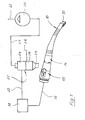
- Fig. 1 is shown by dashed lines at 10 a total of a suction cannula, which has a suction opening 12.
- the suction cannula 10 is connected via a generally designated 14 adapter and a flow control part 15 with a flexible hose 16, which leads to a tray 18.
- the tray 18 is used to hold the tube 16 when it is not needed to work, and other auxiliary equipment that the dentist when working from time to time needed, such. B. a water lance or the like. These details of the tray 18 are not of interest here and therefore not shown in the drawing.
- the tray 18 is connected via a line 20 with a separation unit 22, which consists of a cyclone 24 and a centrifuge 26 arranged thereunder.
- the cyclone 24 separates the air from the inflowing mixture of air, liquid and solid particles and provides them on a clean air line 28, which is connected to the suction side of a suction machine 30. The latter releases the air to the environment via an outlet conduit 32, which in practice is routed via the roof.
- the centrifuge 26 separates the solid particles from the mixture of liquid and solid particles obtained from the cyclone 24 and collects them in a periodically emptied collection container 34.
- the solid particle-free water is provided on a clean water line 36 connected to the public sewer system (not shown) ) connected is.
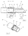
- the adapter 14 will now be described in more detail with reference to FIGS. 2 and 3. It consists of a hose-side adapter part 38 and a cannula-side adapter part 40. These overlap over a in Fig. 2 designated A axial region, wherein an inner nozzle portion 42 of the hose-side adapter part 38 is surrounded by a sleeve portion 44 of the cannula-side adapter part 40. The radial base distance between the nozzle portion 42 and the sleeve portion 44 is just so great that the two adapter parts can be plugged into each other without significant friction.
- the nozzle portion 42 of the adapter part 38 is connected to a slightly larger diameter having coupling portion 46. Received at the crossing point one shoulder 48.
- nozzle portion 42 In the nozzle portion 42 four circumferentially equally distributed flat secondary air channels 50 are provided, which may have a depth of about 0.5 to about 1.0 mm in practice.
- the groove-shaped secondary air channels 50 continue into the coupling section 46 and terminate in ramped deflection surfaces 52.
- the sleeve portion 44 of the adapter part 40 carries a tubular coupling portion 54 of smaller diameter, on which the suction cannula 10 can be pushed.
- a shoulder 56th At the transition point between the sleeve portion 44 and the coupling portion 54 is obtained a shoulder 56th
- a free end surface 58 of the nozzle portion 42 is removed by a small distance from the surface of the shoulder 56, so that one receives between these two surfaces extending in the circumferential direction radial gap 60. This is connected via the secondary air channels 50 and the deflection surfaces 52 in flow communication with the environment.
- a detent skirt 62 is still provided at 62, which is provided in the vicinity of the transition between the sleeve portion 44 and coupling portion 54 and cooperates with a complementary trained locking rib (not shown), which is provided at the rear end of the suction cannula 10.
- the locking skirt 62 is divided by not visible in the drawing axial slots in individual spring fingers, and their locking rib has ramps at both axial ends, so that the suction cannula 10 can detach by pulling the adapter 14 and can lock by pressing axially on this.
- a similar locking connection is provided between the two adapter parts 38 and 40. It comprises four circumferentially equally distributed roof-shaped latching bumps 64 of the adapter part 38 and with these cooperating axial latching fingers 66 of the sleeve portion 44, which are bounded by a plurality of circumferentially distributed axial slots of the sleeve portion 44.
- the latching fingers 66 have, as shown in Fig. 2, on its inside locking grooves, which can cooperate positively with the latching rams 64.
- the sleeve portion 44 On its outer surface, the sleeve portion 44 has four circumferentially distributed depressions 68 which serve as gripping aids to keep the adapter part 40 safe when either the suction cannula 10 is to be withdrawn or the locking connection between the two adapter parts 38, 40 is to be broken.
- the adapter 14 as a whole provides a bleed passage leading to the interior of the hose 16 and is always open. About this secondary air duct but only a limited amount of air is sucked because it has 10 compared to the suction cannula large flow resistance.
- the flow resistance of the secondary air duct is dimensioned such that as much air is sucked into the interior of the hose 16 via the secondary air duct 10 that liquid located on the inner surface of the hose is prevented from flowing under the influence of gravity in the direction of the suction cannister 10 to flow.
- the introduction of the secondary air into the tube 16 is uniform in the circumferential direction, since the secondary air supply via the rotationally symmetric gap 60 takes place, which lies between the end surface 58 and the shoulder 56.
- the gap 62 communicates with the environment via a plurality of circumferentially distributed secondary air channels 50 and inclined inlet portions thereof (deflection surfaces 52), it is ensured that a secondary air flow is not prevented even if the assistant of the dentist one or two of the inlet sections the secondary air channels 50 closes with her finger.
- Throttling the secondary air through small cross-sectional channels does not pose a sanitary risk, as these channels are bounded by surfaces formed on the outer surface of the spigot portion 42 and the inner surface of the sleeve portion 44. These surfaces are freely accessible after separation of the two adapter parts 38, 40 for disinfectant.
- the molded plastic in practice adapter 14 can thus be easily and safely disinfect or sterilize after opening the locking connection between the adapter parts 38, 40 in parts.
Landscapes
- Health & Medical Sciences (AREA)
- Oral & Maxillofacial Surgery (AREA)
- Dentistry (AREA)
- Epidemiology (AREA)
- Life Sciences & Earth Sciences (AREA)
- Animal Behavior & Ethology (AREA)
- General Health & Medical Sciences (AREA)
- Public Health (AREA)
- Veterinary Medicine (AREA)
- Dental Tools And Instruments Or Auxiliary Dental Instruments (AREA)
Applications Claiming Priority (1)
| Application Number | Priority Date | Filing Date | Title |
|---|---|---|---|
| DE102005038636A DE102005038636A1 (de) | 2005-08-13 | 2005-08-13 | Adapter für eine dentale Saugeinrichtung |
Publications (3)
| Publication Number | Publication Date |
|---|---|
| EP1752110A2 true EP1752110A2 (fr) | 2007-02-14 |
| EP1752110A3 EP1752110A3 (fr) | 2010-03-10 |
| EP1752110B1 EP1752110B1 (fr) | 2011-11-16 |
Family
ID=37496550
Family Applications (1)
| Application Number | Title | Priority Date | Filing Date |
|---|---|---|---|
| EP06016800A Not-in-force EP1752110B1 (fr) | 2005-08-13 | 2006-08-11 | Adaptateur pour un système d'aspiration dentaire |
Country Status (2)
| Country | Link |
|---|---|
| EP (1) | EP1752110B1 (fr) |
| DE (1) | DE102005038636A1 (fr) |
Cited By (1)
| Publication number | Priority date | Publication date | Assignee | Title |
|---|---|---|---|---|
| EP1955672A1 (fr) | 2007-02-06 | 2008-08-13 | Dürr Dental GmbH & Co. KG | Canule d'aspiration pour un dispositif d'aspiration dentaire |
Families Citing this family (1)
| Publication number | Priority date | Publication date | Assignee | Title |
|---|---|---|---|---|
| DE202019001370U1 (de) | 2019-03-25 | 2020-06-29 | Coltène/Whaledent GmbH + Co. KG | Zweiteilige Absaugkanüle für dentalmedizinische Behandlungen |
Citations (1)
| Publication number | Priority date | Publication date | Assignee | Title |
|---|---|---|---|---|
| EP0457220A1 (fr) | 1990-05-14 | 1991-11-21 | Colin Dr. Nates | Dispositifs de succion |
Family Cites Families (3)
| Publication number | Priority date | Publication date | Assignee | Title |
|---|---|---|---|---|
| US3881254A (en) * | 1974-02-06 | 1975-05-06 | Louis C Epstein | Saliva ejector |
| US4083115A (en) * | 1976-03-15 | 1978-04-11 | Mckelvey Thomas H | Dental saliva ejector |
| DE8030146U1 (de) * | 1980-11-12 | 1981-03-12 | Hatzfeld, Hermann, 6490 Schlüchtern | Zahnaerztliche absaugkanuele |
-
2005
- 2005-08-13 DE DE102005038636A patent/DE102005038636A1/de not_active Withdrawn
-
2006
- 2006-08-11 EP EP06016800A patent/EP1752110B1/fr not_active Not-in-force
Patent Citations (1)
| Publication number | Priority date | Publication date | Assignee | Title |
|---|---|---|---|---|
| EP0457220A1 (fr) | 1990-05-14 | 1991-11-21 | Colin Dr. Nates | Dispositifs de succion |
Cited By (1)
| Publication number | Priority date | Publication date | Assignee | Title |
|---|---|---|---|---|
| EP1955672A1 (fr) | 2007-02-06 | 2008-08-13 | Dürr Dental GmbH & Co. KG | Canule d'aspiration pour un dispositif d'aspiration dentaire |
Also Published As
| Publication number | Publication date |
|---|---|
| EP1752110B1 (fr) | 2011-11-16 |
| DE102005038636A1 (de) | 2007-02-15 |
| EP1752110A3 (fr) | 2010-03-10 |
Similar Documents
| Publication | Publication Date | Title |
|---|---|---|
| EP3915514B1 (fr) | Dispositif d'aspiration à manche pour une unité de traitement dentaire ainsi que dispositif d'aspiration doté d'un dispositif d'aspiration à manche | |
| EP2723413B1 (fr) | Système destiné à aspirer des fluides hors d'un corps par un effet de dépression | |
| EP3542759B1 (fr) | Espaceur fémorale de l'articulation de la hanche pourvu de dispositif de rinçage | |
| EP2152334B1 (fr) | Unité à pompe de drainage | |
| DE2713321C2 (de) | Verfahren und Vorrichtung zum Abscheiden von flüssigen und festen Bestandteilen aus dem aus dem Mund eines Patienten kommenden Saugmediengemisch | |
| DE3819257C1 (fr) | ||
| DE9017505U1 (de) | Gerät für die Spülung und Drainierung von Wunden | |
| DE2900376A1 (de) | Blasenkatheter-spuelvorrichtung | |
| DE3412667A1 (de) | Vorrichtung zum reinigen von kanaelen in einem endoskop | |
| DE19646584C1 (de) | Einrichtung und Verfahren zum Spülen von Kanälen medizinischer Instrumente | |
| EP1044655B1 (fr) | Dispositif dentaire pour le traitement des tissus préférablement avec oscillations mécaniques à haute fréquence | |
| EP1261390B1 (fr) | Dispositif pour introduire un catheter dans l'uretre | |
| DE69214690T2 (de) | Vorrichtung für die Wäsche, aus therapeutischen oder hygienischen Gründen, von menschlichen oder tierischen internen Leitungen | |
| EP3714837B1 (fr) | Canule d'aspiration en deux pièces pour traitements médicaux dentaires | |
| EP4046671B1 (fr) | Agencement de rinçage | |
| EP1752110B1 (fr) | Adaptateur pour un système d'aspiration dentaire | |
| EP4404868A1 (fr) | Canule dentaire pour une seringue dentaire pour évacuer des substances | |
| AT402148B (de) | Verfahren und vorrichtung zur dosierten einbringung von pflege-, reinigungs- und/oder desinfektionsflüssigkeiten in zahnärztliche absauganlagen | |
| DE3805609C2 (fr) | ||
| EP0633751B1 (fr) | Agencement dans un systeme d'aspiration utilise en medecine dentaire | |
| EP1514575B1 (fr) | Dispositif pour nettoyer des connecteurs de type Luer-Lock | |
| AT402149B (de) | Verfahren und vorrichtung zur pflege, reinigung und/oder desinfektion von absauganlagen in zahnärztlichen praxen | |
| DE102016215633B4 (de) | Melkbecherhülse und modulares Melkbecherhülsensystem | |
| DE19720933C2 (de) | Geschlossenes Urin-Drainagesystem mit wiederverwendbarem Urinauffangbehälter | |
| DE3231693C2 (fr) |
Legal Events
| Date | Code | Title | Description |
|---|---|---|---|
| PUAI | Public reference made under article 153(3) epc to a published international application that has entered the european phase |
Free format text: ORIGINAL CODE: 0009012 |
|
| AK | Designated contracting states |
Kind code of ref document: A2 Designated state(s): AT BE BG CH CY CZ DE DK EE ES FI FR GB GR HU IE IS IT LI LT LU LV MC NL PL PT RO SE SI SK TR |
|
| AX | Request for extension of the european patent |
Extension state: AL BA HR MK YU |
|
| RAP1 | Party data changed (applicant data changed or rights of an application transferred) |
Owner name: DUERR DENTAL AG |
|
| PUAL | Search report despatched |
Free format text: ORIGINAL CODE: 0009013 |
|
| AK | Designated contracting states |
Kind code of ref document: A3 Designated state(s): AT BE BG CH CY CZ DE DK EE ES FI FR GB GR HU IE IS IT LI LT LU LV MC NL PL PT RO SE SI SK TR |
|
| AX | Request for extension of the european patent |
Extension state: AL BA HR MK RS |
|
| 17P | Request for examination filed |
Effective date: 20100910 |
|
| 17Q | First examination report despatched |
Effective date: 20101014 |
|
| AKX | Designation fees paid |
Designated state(s): DE FR IT |
|
| GRAP | Despatch of communication of intention to grant a patent |
Free format text: ORIGINAL CODE: EPIDOSNIGR1 |
|
| RIC1 | Information provided on ipc code assigned before grant |
Ipc: A61C 17/08 20060101AFI20110420BHEP |
|
| GRAS | Grant fee paid |
Free format text: ORIGINAL CODE: EPIDOSNIGR3 |
|
| GRAA | (expected) grant |
Free format text: ORIGINAL CODE: 0009210 |
|
| AK | Designated contracting states |
Kind code of ref document: B1 Designated state(s): DE FR IT |
|
| REG | Reference to a national code |
Ref country code: DE Ref legal event code: R081 Ref document number: 502006010589 Country of ref document: DE Owner name: DUERR DENTAL SE, DE Free format text: FORMER OWNER: DUERR DENTAL GMBH & CO. KG, 74321 BIETIGHEIM-BISSINGEN, DE |
|
| REG | Reference to a national code |
Ref country code: DE Ref legal event code: R096 Ref document number: 502006010589 Country of ref document: DE Effective date: 20120119 |
|
| PLBE | No opposition filed within time limit |
Free format text: ORIGINAL CODE: 0009261 |
|
| STAA | Information on the status of an ep patent application or granted ep patent |
Free format text: STATUS: NO OPPOSITION FILED WITHIN TIME LIMIT |
|
| 26N | No opposition filed |
Effective date: 20120817 |
|
| REG | Reference to a national code |
Ref country code: DE Ref legal event code: R097 Ref document number: 502006010589 Country of ref document: DE Effective date: 20120817 |
|
| REG | Reference to a national code |
Ref country code: FR Ref legal event code: ST Effective date: 20130430 |
|
| PG25 | Lapsed in a contracting state [announced via postgrant information from national office to epo] |
Ref country code: FR Free format text: LAPSE BECAUSE OF NON-PAYMENT OF DUE FEES Effective date: 20120831 |
|
| PGFP | Annual fee paid to national office [announced via postgrant information from national office to epo] |
Ref country code: IT Payment date: 20140826 Year of fee payment: 9 |
|
| PG25 | Lapsed in a contracting state [announced via postgrant information from national office to epo] |
Ref country code: IT Free format text: LAPSE BECAUSE OF NON-PAYMENT OF DUE FEES Effective date: 20150811 |
|
| REG | Reference to a national code |
Ref country code: DE Ref legal event code: R082 Ref document number: 502006010589 Country of ref document: DE Representative=s name: OSTERTAG & PARTNER, PATENTANWAELTE MBB, DE Ref country code: DE Ref legal event code: R081 Ref document number: 502006010589 Country of ref document: DE Owner name: DUERR DENTAL SE, DE Free format text: FORMER OWNER: DUERR DENTAL AG, 74321 BIETIGHEIM-BISSINGEN, DE |
|
| PGFP | Annual fee paid to national office [announced via postgrant information from national office to epo] |
Ref country code: DE Payment date: 20220819 Year of fee payment: 17 |
|
| REG | Reference to a national code |
Ref country code: DE Ref legal event code: R119 Ref document number: 502006010589 Country of ref document: DE |
|
| PG25 | Lapsed in a contracting state [announced via postgrant information from national office to epo] |
Ref country code: DE Free format text: LAPSE BECAUSE OF NON-PAYMENT OF DUE FEES Effective date: 20240301 |