EP0457225A1 - Regelung der Zugabe von Konditionierungsmitteln in Abgasen - Google Patents
Regelung der Zugabe von Konditionierungsmitteln in Abgasen Download PDFInfo
- Publication number
- EP0457225A1 EP0457225A1 EP91107684A EP91107684A EP0457225A1 EP 0457225 A1 EP0457225 A1 EP 0457225A1 EP 91107684 A EP91107684 A EP 91107684A EP 91107684 A EP91107684 A EP 91107684A EP 0457225 A1 EP0457225 A1 EP 0457225A1
- Authority
- EP
- European Patent Office
- Prior art keywords
- flue gas
- conditioning agents
- addition
- conditioning
- electrostatic precipitator
- Prior art date
- Legal status (The legal status is an assumption and is not a legal conclusion. Google has not performed a legal analysis and makes no representation as to the accuracy of the status listed.)
- Granted
Links
Images
Classifications
-
- F—MECHANICAL ENGINEERING; LIGHTING; HEATING; WEAPONS; BLASTING
- F23—COMBUSTION APPARATUS; COMBUSTION PROCESSES
- F23J—REMOVAL OR TREATMENT OF COMBUSTION PRODUCTS OR COMBUSTION RESIDUES; FLUES
- F23J15/00—Arrangements of devices for treating smoke or fumes
- F23J15/02—Arrangements of devices for treating smoke or fumes of purifiers, e.g. for removing noxious material
-
- B—PERFORMING OPERATIONS; TRANSPORTING
- B01—PHYSICAL OR CHEMICAL PROCESSES OR APPARATUS IN GENERAL
- B01D—SEPARATION
- B01D53/00—Separation of gases or vapours; Recovering vapours of volatile solvents from gases; Chemical or biological purification of waste gases, e.g. engine exhaust gases, smoke, fumes, flue gases, aerosols
- B01D53/34—Chemical or biological purification of waste gases
- B01D53/346—Controlling the process
-
- B—PERFORMING OPERATIONS; TRANSPORTING
- B03—SEPARATION OF SOLID MATERIALS USING LIQUIDS OR USING PNEUMATIC TABLES OR JIGS; MAGNETIC OR ELECTROSTATIC SEPARATION OF SOLID MATERIALS FROM SOLID MATERIALS OR FLUIDS; SEPARATION BY HIGH-VOLTAGE ELECTRIC FIELDS
- B03C—MAGNETIC OR ELECTROSTATIC SEPARATION OF SOLID MATERIALS FROM SOLID MATERIALS OR FLUIDS; SEPARATION BY HIGH-VOLTAGE ELECTRIC FIELDS
- B03C3/00—Separating dispersed particles from gases or vapour, e.g. air, by electrostatic effect
- B03C3/01—Pretreatment of the gases prior to electrostatic precipitation
- B03C3/013—Conditioning by chemical additives, e.g. with SO3
-
- Y—GENERAL TAGGING OF NEW TECHNOLOGICAL DEVELOPMENTS; GENERAL TAGGING OF CROSS-SECTIONAL TECHNOLOGIES SPANNING OVER SEVERAL SECTIONS OF THE IPC; TECHNICAL SUBJECTS COVERED BY FORMER USPC CROSS-REFERENCE ART COLLECTIONS [XRACs] AND DIGESTS
- Y10—TECHNICAL SUBJECTS COVERED BY FORMER USPC
- Y10S—TECHNICAL SUBJECTS COVERED BY FORMER USPC CROSS-REFERENCE ART COLLECTIONS [XRACs] AND DIGESTS
- Y10S55/00—Gas separation
- Y10S55/30—Exhaust treatment
Definitions
- coal In a coal-fired power plant, coal is burned to heat air, which in turn boils water to form steam. The steam drives a turbine and thence an electric generator, producing electricity. Besides heat, the burning of the coal produces gaseous pollutants such as sulfur and nitrogen oxides, and a solid particulate known as fly ash.
- gaseous pollutants such as sulfur and nitrogen oxides
- fly ash a solid particulate known as fly ash.
- Environmental protection laws mandate that the amounts of gaseous pollutants and solid particulate emitted from the power plant be maintained at acceptably low levels, and the present invention deals generally with the technology for controlling particulate emissions.
- the flue gas stream with entrained particulate is passed between highly charged electrodes that ionize the particles so that they are attracted to, and deposited upon, a collection electrode.
- the particulate may optionally be charged prior to entry into the precipitator to increase the efficiency of removal.
- the cleaned combustion gases are released to the atmosphere, and the precipitated particulate is removed from the collection electrode.
- a conditioning gas such as sulfur trioxide is injected into the combustion gas stream.
- the sulfur trioxide reacts with moisture in the gas stream to produce sulfuric acid that is deposited upon the surface of the particulate.
- the sulfuric acid reduces the electrical resistance of the particulate, which is equivalent to raising the electrical conductivity of the fly ash particulate, so that the electrostatic precipitation treatment works well.
- Conditioning treatments are routinely used where the sulfur content of the coal burned in the power plant is so low that the electrical resistivity of the resulting particulate is too high to permit the electrostatic precipitators to operate properly.
- ammonia reduces the amount of residual sulfur trioxide in the flue gas by forming ammonium sulfates and bisulfates.
- the ammonium bisulfates have the added beneficial effect of acting as a binder of the deposited fly ash in the electrostatic precipitator, so that there is a decreased likelihood that deposited fly ash can become reentrained in the gas stream to be exhausted through the stack and into the atmosphere.
- the present invention provides a method and apparatus for controlling the addition of conditioning agents to flue gas streams containing particulate matter.
- the approach utilizes measurements of system performance as the basis for feedforward and feedback control of the conditioning agent flow rates. It requires no direct operator input, and therefore is not affected by variations in operator judgment.
- the proper amounts of conditioning agents may be added to reach and maintain optimum or near-optimum system performance.
- apparatus for controlling the addition of conditioning agents to a particulate-containing flue gas stream that subsequently passes through a set of precipitation electrodes of an electrostatic precipitator before being exhausted to the atmosphere comprises a feedforward sensor that senses the flue gas and provides a feedforward signal indicative of the mass flow rate of particulate matter in the flue gas prior to the addition of the conditioning agents; a feedback sensor that senses the flue gas after the addition of the conditioning agents, and produces a feedback signal indicative thereof; and a controller that receives the feedforward signal and the feedback signal, and adjusts the amounts of the conditioning agents added to the flue gas stream based upon the values of the signals.
- the present system is operable when one conditioning agent is used, but its advantages are most effectively realized when two or more conditioning agents are used.
- the "feedforward" signal is one that is measured at a location prior to (upstream of) the point where the conditioning agents are added to the flue gas stream. It preferably is used to indicate the general magnitude, volume, and mass of the particulate matter in the flue gas stream.
- Some typical feedforward signals are the boiler load, which can be measured as the flow rate of the gas stream from the boiler, fuel flow, the heat input to the boiler, or a related signal that can be correlated to boiler load.
- the "feedback” signal is one that is measured at a location subsequent to (downstream from) the point where the conditioning agents are added to the flue gas stream. It is used to indicate the effect of the conditioning agents.
- Typical feedback signals include one or more of the quantities opacity of the stack gas, the residual ammonia level of the effluent gas stream, the residual sulfur trioxide level of the effluent gas stream, and the power consumption of the electrostatic precipitator. Where two or more conditioning agents are used, two or more feedback signals may be used essentially simultaneously.
- a process for controlling the addition of conditioning agents to a stream of a flue gas containing particulate matter in a flue gas cleanup system having a conditioning agent injector, an electrostatic precipitator to which the flue gas passes after the conditioning agent is added, and an exhaust from the electrostatic precipitator comprises the steps of sensing the flue gas prior to the addition of the conditioning agent, and providing a feedforward signal indicative of the mass flow rate of the flue gas; sensing the flue gas after the addition of the conditioning agent, and providing a feedback signal indicative thereof; and controlling the amounts of the conditioning agents added to the flue gas stream based upon the values of the feedforward signal and the feedback signal.
- the required changes in the total flow rates of the conditioning agents are related to the feedforward signal indicative of particulate output. For example, if the feedforward signal were to double within a relatively short time, indicating a doubling of the mass flow rate of flue gas and thence particulate matter, the flow rates of the conditioning agents per unit time would be adjusted accordingly, in a typical case to double their prior values. That is, the flow rates of the conditioning agents in parts per million of flue gas would remain constant, but since the flue gas mass flow per unit time had doubled, the flow rates of the conditioning agents in mass per unit time would also be doubled.
- the present approach provides both a coarse control, the feedforward signal, and a fine control, the feedback signals, for controlling the flow rates of the conditioning agents.
- the feedback signals would be sufficient to attain optimized performance over long periods of time, the nonoptimal performance during the search for the optimum performance control points would result in large amounts of particulate lost to the atmosphere.
- the coarse control using the feedforward signal allows the conditioning flows to be adjusted to reach near-optimum total flows more quickly, reducing the amount of particulate lost to the atmosphere as the optimum point is sought.
- the various feedforward and feedback signals are measured by commercially available sensors, and analyzed by the controller.
- the controller adjusts the mass flow rates per unit time of the conditioning agents in a continuous manner, without the need for human intervention.
- the approach accommodates the peculiarities of gas cleanup systems and their operation, and can be made to reflect the operating behavior of particular power plants. It therefore permits the flue gas composition to be controlled to achieve the best stack gas composition possible.
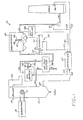
- the present invention is preferably used in conjunction with an apparatus 10 for precipitating particulate from a combustion gas stream, which is depicted in Figure 1.
- a coal-fired power plant coal is burned by a combustor 12, and the resulting hot flue or combustion gas is passed through a boiler 14, where it heats and boils water.
- the resulting steam in a loop 16 flows to a turbine/generator set 18, where electricity for consumption is produced.
- the steam is condensed, and the water flows back through the loop 16.
- the fly ash produced by some types of coal particularly many coals containing a low sulfur content, has too high an electrical resistance to be processed in a collection device such as an electrostatic precipitator, and therefore must be conditioned before entering the precipitator. It is known to inject conditioning agents into the combustion gas stream, as illustrated schematically in Figure 1.
- a first conditioning apparatus 30 injects a first conditioning agent (that may be a gas, a liquid, or a solid, but is preferably a gas) into the flue gas stream 20.
- the first conditioning agent is preferably sulfur trioxide (SO3).
- the preferred first conditioning apparatus 30 therefore includes a source 31 of sulfur trioxide, and a plurality of sulfur trioxide injector nozzles 32 that extend into the flue gas stream 20 to inject the sulfur trioxide directly into the stream 20.
- a flow control device 33 such as a valve that controls the flow of sulfur or other feedstock for producing sulfur trioxide, meters the conditioning gas into the combustion gas stream 20 through the nozzles 32.
- a preferred source 31 is disclosed in US patent 3,993,429, and a preferred construction of the nozzles 32 is disclosed in US patent 4,179,071. The disclosures of both of these patents are incorporated herein by reference.
- the injected sulfur trioxide reacts with moisture in the gas stream 20, and the resulting sulfuric acid deposits upon the particulate in the gas stream to increase its conductivity, or, alternatively stated, to lower its resistivity. More specifically, the sulfur trioxide reacts with the residual moisture in the flue gas stream to form sulfuric acid on the surface of the particulate, which increases the electrical conductivity of the particulate.
- the flue gas 20 optionally passes through an air preheater 38, which is a heat exchanger that removes heat from the flue gas stream and heats the air that is used to burn the fuel in the combustor 12.
- an air preheater 38 which is a heat exchanger that removes heat from the flue gas stream and heats the air that is used to burn the fuel in the combustor 12.
- the sulfur trioxide conditioning agent is injected upstream of the air preheater 38, where the temperature of the flue gas is typically about 400°C.
- a second conditioning agent preferably ammonia
- a second conditioning apparatus 34 for adding ammonia gas includes a source 35 for the gas, a valve 36 that regulates the flow of the gas, and an injector 37 of the same general type as the injector 32.
- the ammonia source 35 is preferably simply a tank of liquid ammonia with a heater to gasify the required amount of liquid, and ammonia is not formed by reaction at the site of the power plant.
- the precipitator 40 may be of any of the many types commercially available and known in the art.
- the precipitator 40 includes a plurality of electrodes 42 charged with a high voltage, and grounded precipitation plates 44.
- the particulate in the gas stream 20 is charged by the electrostatic field established between the electrodes 42 and the plates 44, and is attracted to be deposited as a layer of dust 46 upon the plates 44 for subsequent removal.
- the layer 46 When the layer 46 becomes so thick that its electrical resistivity rises and prevents efficient further removal of the particulate, the layer 46 is removed by "rapping" by rapping hammers (not shown) that physically strike the plates 44 so that the particulate in the layer 46 falls into hoppers 47 below the plates 44. The plates are thereby cleaned and made ready for further collection of particulate.
- rapping hammers (not shown) that physically strike the plates 44 so that the particulate in the layer 46 falls into hoppers 47 below the plates 44.
- the plates are thereby cleaned and made ready for further collection of particulate.
- One particularly troublesome source of particulate in the flue gas leaving the electrostatic precipitator is particulate that is reentrained in the gas stream after having been precipitated electrostatically. Reentrainment can result from a fast moving flue gas stream, and typically is most severe during rapping.
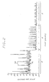
- Figure 2 is an exemplary graph of the measured opacity of the flue gas stream after it has left the electrostatic precipitator.
- the major spikes that occur periodically, indicated by numeral 78, are correlated to rapping events in the precipitator.
- the opacity level between the spikes, numeral 76, corresponds to the passthrough of particulate during normal operation of the electrostatic precipitator.
- Figure 2(c) is the measured opacity when a larger amount (here 17 parts per million) of sulfur trioxide is added to the flue gas stream and a substantial amount (here 17 parts per million) of ammonia is also added.
- the steady state opacity between spikes is reduced further as compared with Figures 2(a) and 2(b), and, significantly, the opacity spikes are greatly reduced in magnitude as compared with either Figure 2(a) or Figure 2(b).
- Proper additions of sulfur trioxide and ammonia can therefore have a beneficial effect upon the power plant emissions.
- the present invention relates to the control of the amount of conditioning agents added by the apparatus 30 and 34, to achieve the most acceptable combination of gaseous emission and particulate levels in the flue gas as it leaves the electrostatic precipitator and passes up the stack for release to the atmosphere.
- the following paragraphs provide a brief summary of the chemical and physical interactions resulting from the injection of the conditioning agents.
- ammonium bisulfate on the surface of the particulate may act in the manner of a binding agent, binding the particulate together in the electrostatic precipitator. This binding action desirably reduces the tendency for reentrainment of the particulate after deposition in the dust layer 46, and particularly during rapping, thereby reducing the emitted particulate in the stack gas.
- the ammonium sulfate can also have an effect upon the efficiency of the electrostatic precipitator by modifying the space charge within the collecting elements.
- a controller 60 receives feedforward and feedback signals indicative of the state of the flue gas stream 20, and adjusts the flow rates of the conditioning agents responsive to particular control procedures within the controller 60.
- the preferred feedforward signal is a boiler load signal 62, sent to the controller 60 from a boiler load sensor 64.
- the boiler load sensor 64 which is preferably a flow meter, measures the rate at which fuel is burned within the combustor 12, as a measure of the total volume or mass of flue gas and particulate that must be conditioned.
- the heat produced, the flow rate of flue gas, the flow rate of water in the boiler, the electrical output of the plant, or other acceptable factors could provide this indication of the total flue gas and particulate loading that must be conditioned.
- the power consumption of the electrostatic precipitator 40 is provided as a power consumption signal 66 from the electrostatic precipitator controller 48 to the injection controller 60.
- the power consumption of the electrostatic precipitator is the power, voltage times current, flowing between the electrodes 42 and the plates 44. Since electrostatic deposition fundamentally occurs by the conduction of charge by the particulate matter deposited in the layer 46, when more power is consumed by the precipitator 40, more particulate is removed from the flue gas stream 20.
- the power consumption of the electrostatic precipitator is a numerical value readily available from all modern commercial controllers 48, and therefore no new instrumentation is required.
- a third preferred type of feedback signal is a stack gas opacity signal 72, which is measured by a stack gas opacity sensor 74 and provided to the controller 60.
- the sensor 74 measures the transmission of a beam of light through the stack gas (as the flue gas is termed after it leaves the electrostatic precipitator).
- the opacity is most directly responsive to the particulate level in the stack gas.
- Acceptable opacity analyzers that may be used as the sensor 74, are available commercially and include the Lear Siegler Model RM 41.
- the various feedforward and feedback signals are indicated in Figure 1 as being provided to the controller 60.
- the signals are provided automatically, as with a digital readout of the sensor or through an analog-to-digital conversion of an analog readout of the sensor. Equivalently, the signal can be hand-fed to the controller 60, as by typing in the signal value.
- An automatic input is preferred, as it permits the taking of many samples and building a statistical data base, without the need for human intervention.
- feedforward and feedback signals are utilized by the controller 60 to determine and control the optimum flow rates of the conditioning agents.
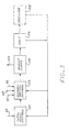
- the general procedure for the operation of the controller is illustrated in Figure 3.
- the feedforward signal 62 is provided to a total flow control function 120, which determines the total flow rates of each of the conditioning agents, in units such as pounds injected per unit time.
- the total flow control function 120 may be based upon a simple linear relation between boiler load and total flow rates, for example. Under such a linear relationship, if for example the total flow rate of flue gas in mass per unit time as measured by the feedforward signal 62 is doubled, the mass flow rate of conditioning agents in mass per unit time, injected by apparatus 30 and 34, is also doubled. More complex relationships may also be used, as appropriate for a particular power plant. That is, it may be known from experience that in certain operating regimes the relation between flow rate of conditioning agents and flow rate of flue gas is nonlinear, and this experience is programmed into the controller 60.
- control function 122 includes the capability to introduce such delays where necessary. For example, depending upon the construction of a particular system, there may be a delay of as much as several hours between an increase in the sulfur trioxide injection concentration and an increase in one of the feedback signals whose origin can be traced to the increased sulfur trioxide injection. Such time delays are measured during initial calibration of the power plant and the control system, and incorporated into the programming.
- Figure 3 shows in dashed lines a perturb block 128 that may be utilized in the control procedure. Because at this time there is not a complete scientific understanding of all of the chemical and physical interactions occurring in the system, it is not possible to know whether true optimum values of the flow rates of the conditioning agents have been reached, or whether a particular set of operating values may be a local optimum resulting from the nature of the interactions. In the future, some complete closed form or parametric understanding of the interactions may be discovered, but that is not available now. Therefore, to test the effect of changes in the flow rate of one of the conditioning agents upon the overall system performance, that flow rate can be forced to a value which the control functions 120 and 122 did not select.
- the total flow rate in mass per unit time of each of the conditioning agents is determined from the feedforward boiler load signal 62 and a linear relation or calibration curve for the plant.
- the ratio of the two conditioning agents is determined in one of four ways.
- a portion of the total flow of the sulfur trioxide and ammonia conditioning agents is established according to a preselected ratio.
- the preselected ratio is determined for the power plant during calibration as its best performance characteristic.
- a second portion of conditioning agents is added to these amounts, and typically the second portion is additional sulfur trioxide.
- the relative amount of the first portion is established responsive to the opacity signal 72, to minimize particulate loss to the stack gas.
- the relative amount of the second portion is established responsive to the electrostatic precipitator power consumption signal 66, to maximize that value.
- the relative amount of the second portion can also be controlled responsive to the residual sulfur signal 68, to minimize that value.
- the total flow rate of sulfur trioxide is adjusted responsive to the electrostatic power consumption signal 66 or the residual sulfur signal 68, as just described for the second portion under the first embodiment.
- the total flow rate of injected ammonia is adjusted to minimize the opacity signal 72, since the ammonia can increase the adherence of the particulate to resist reentrainment.
- the flow rate of ammonia is controlled in response to the opacity signal 72.
- the sulfur trioxide is adjusted according to a preset ratio with the ammonia.
- the sulfur trioxide and the ammonia flows can be adjusted independently, as long as the total flow of the conditioning agents is that required by the total flow computation based upon the feedforward signal.
- the functional operation of this embodiment will be described by way of illustration of the optimization and perturbation processes.
- the sulfur trioxide injection flow rate increases from below an optimum value, the power consumption of the electrostatic precipitator increases and the opacity spikes during rapping increase.
- the ammonia content can then be increased relative to the sulfur trioxide content, which reduces the effective sulfur trioxide content as a result of the ammonium bisulfate reaction.
- the precipitator power may decrease so that the total capture of particulate decreases, but at the same time the deposition of ammonium bisulfate on the particulate matter results in smaller opacity spikes during rapping.
- minima in emissions or optimal values can be discerned.
- the selected operating values may not be the mathematical joint minimal values, due to environmental laws that are more stringent for some emissions than for others and economic considerations such as the difficulty in selling recovered fly ash that is high in ammonia content.
- Such legal constraints are provided to the controller in the form of constraints or weighting factors for decision making.
- the perturbation function can optionally be used to intentionally change a flow rate away from the solution to ascertain the effect on the other flow rates.
- the system will find a new set of flow rates which may be even better than the prior solution, and the system then adopts that solution. If at a later time the feedforward signal changes, indicating a change, in total flue gas flow and thence particulate flow, the optimization procedure is repeated.
- Each optimal set of operating conditions is stored in the computer memory, and the control functions 120 and 122 check these values during optimization. In this way, prior experience is used to reduce the time needed to reach the best combination of conditioning agents for any particular operating conditions. The reduction in the search time to reach the desired combination reduces the time that the system operates in a non-optimal condition with higher emissions.
- the present invention thus provides a general apparatus and method for controlling the flow rates of additions of conditioning agents to flue gas streams of power plants. While general in form, the control process is particularized to an individual power plant, its operational characteristics, the type of coal used, and individual restrictions in the environmental laws, through calibration of the control system with actual power plant performance information.
Landscapes
- Engineering & Computer Science (AREA)
- Chemical & Material Sciences (AREA)
- Chemical Kinetics & Catalysis (AREA)
- General Chemical & Material Sciences (AREA)
- Health & Medical Sciences (AREA)
- Environmental & Geological Engineering (AREA)
- Biomedical Technology (AREA)
- Analytical Chemistry (AREA)
- General Engineering & Computer Science (AREA)
- Oil, Petroleum & Natural Gas (AREA)
- Mechanical Engineering (AREA)
- Treating Waste Gases (AREA)
- Electrostatic Separation (AREA)
Applications Claiming Priority (2)
| Application Number | Priority Date | Filing Date | Title |
|---|---|---|---|
| US07/523,311 US5029535A (en) | 1990-05-14 | 1990-05-14 | Control of addition of conditioning agents to flue gas |
| US523311 | 1990-05-14 |
Publications (2)
| Publication Number | Publication Date |
|---|---|
| EP0457225A1 true EP0457225A1 (de) | 1991-11-21 |
| EP0457225B1 EP0457225B1 (de) | 1995-09-06 |
Family
ID=24084493
Family Applications (1)
| Application Number | Title | Priority Date | Filing Date |
|---|---|---|---|
| EP91107684A Expired - Lifetime EP0457225B1 (de) | 1990-05-14 | 1991-05-11 | Regelung der Zugabe von Konditionierungsmitteln in Abgasen |
Country Status (7)
| Country | Link |
|---|---|
| US (1) | US5029535A (de) |
| EP (1) | EP0457225B1 (de) |
| AT (1) | ATE127365T1 (de) |
| AU (1) | AU631313B2 (de) |
| CA (1) | CA2042506A1 (de) |
| DE (1) | DE69112702D1 (de) |
| ES (1) | ES2080852T3 (de) |
Cited By (1)
| Publication number | Priority date | Publication date | Assignee | Title |
|---|---|---|---|---|
| CN110652845A (zh) * | 2019-09-12 | 2020-01-07 | 常熟浦发第二热电能源有限公司 | 一种垃圾焚烧炉烟气脱酸反应塔前馈控制方法 |
Families Citing this family (34)
| Publication number | Priority date | Publication date | Assignee | Title |
|---|---|---|---|---|
| US5032154A (en) * | 1989-04-14 | 1991-07-16 | Wilhelm Environmental Technologies, Inc. | Flue gas conditioning system |
| US5350441A (en) * | 1990-03-15 | 1994-09-27 | Wilhelm Environmental Technologies, Inc. | Flue gas conditioning system |
| US5196038A (en) * | 1990-03-15 | 1993-03-23 | Wright Robert A | Flue gas conditioning system |
| PL168065B1 (pl) * | 1990-08-17 | 1995-12-30 | Fritz Schoppe | Sposób i urzadzenie do calkowitego suchego odsiarczania gazów spalinowych PL |
| ATE121311T1 (de) * | 1991-01-30 | 1995-05-15 | Stadt Landshut Vertreten Durch | Verfahren zur rauchgasreinigung von feuerungsanlagen, insbesondere müllverbrennungsanlagen. |
| US5176088A (en) * | 1992-01-10 | 1993-01-05 | The Babcock & Wilcox Company | Furnace ammonia and limestone injection with dry scrubbing for improved simultaneous SOX and NOX removal |
| US5356597A (en) * | 1992-04-07 | 1994-10-18 | Wilhelm Environmental Technologies, Inc. | In-duct flue gas conditioning system |
| US5288303A (en) * | 1992-04-07 | 1994-02-22 | Wilhelm Environmental Technologies, Inc. | Flue gas conditioning system |
| US5240470A (en) * | 1992-04-07 | 1993-08-31 | Wilhelm Environmental Technologies, Inc. | In-duct flue gas conditioning system |
| WO1993019852A1 (en) * | 1992-04-07 | 1993-10-14 | Wilhelm Environmental Technologies, Inc. | Flue gas conditioning system |
| US5244642A (en) * | 1992-06-18 | 1993-09-14 | The Chemithon Corporation | Method for conditioning flue gas |
| US5567226A (en) * | 1992-10-09 | 1996-10-22 | Lookman; Aziz A. | Apparatus and method for enhancing the performance of a particulate collection device |
| DE4234163A1 (de) * | 1992-10-09 | 1994-04-14 | Siemens Ag | Schwel-Brenn-Verfahren sowie Schwel-Brenn-Anlage mit Drucksteuerung |
| US5370720A (en) * | 1993-07-23 | 1994-12-06 | Welhelm Environmental Technologies, Inc. | Flue gas conditioning system |
| USD364946S (en) | 1993-08-18 | 1995-12-05 | Stenovich Donald A | Emissions scrubber for wood burning units |
| DE4344112C2 (de) * | 1993-12-23 | 1998-10-22 | Metallgesellschaft Ag | Verfahren zur Steuerung der Sorptionsleistung eines Filtrationsabscheiders |
| US5553555A (en) * | 1994-04-28 | 1996-09-10 | Dasibi Environmental Corporation | System and method for flue gas purification for thermal power units |
| US5795548A (en) * | 1996-03-08 | 1998-08-18 | Mcdermott Technology, Inc. | Flue gas desulfurization method and apparatus |
| RU2123619C1 (ru) * | 1998-06-25 | 1998-12-20 | Белевич Алексей Игоревич | Парожидкостный струйный аппарат с давлением жидкости на выходе, превышающим давление рабочего газа |
| US6233526B1 (en) * | 1998-07-16 | 2001-05-15 | Micro Motion, Inc. | Vibrating conduit parameter sensors and methods of operation therefor utilizing spatial integration |
| US6093380A (en) * | 1998-10-16 | 2000-07-25 | Siirtec Nigi, S.P.A. | Method and apparatus for pollution control in exhaust gas streams from fossil fuel burning facilities |
| US6152053A (en) * | 1999-07-30 | 2000-11-28 | Abb Alstom Power Inc. | Method and assembly for converting waste water accumulated in a fossil fuel-fired power generation system |
| US20030143501A1 (en) * | 2002-01-31 | 2003-07-31 | Ferrigan James J. | Method and apparatus for sulfur trioxide flue gas conditioning |
| US7574968B2 (en) * | 2002-10-08 | 2009-08-18 | Energy & Environmental Research Center | Method and apparatus for capturing gas phase pollutants such as sulfur trioxide |
| US20040191709A1 (en) * | 2003-03-26 | 2004-09-30 | Miller Eric S. | Economizer bypass with ammonia injection |
| CA2521584C (en) * | 2003-04-11 | 2012-07-31 | Stockhausen, Inc. | A reduced-emissions fossil-fuel-fired system |
| US8079845B2 (en) * | 2005-05-10 | 2011-12-20 | Environmental Energy Services, Inc. | Processes for operating a utility boiler and methods therefor |
| US20080267837A1 (en) * | 2007-04-27 | 2008-10-30 | Phelps Calvin E | Conversion of urea to reactants for NOx reduction |
| US8955763B2 (en) * | 2007-10-04 | 2015-02-17 | Consolidated Edison Company Of New York, Inc. | Building heating system and method of operation |
| US20100292934A1 (en) * | 2009-05-15 | 2010-11-18 | Baker Hughes Incorporated | Emissions analyzer and methods of using same |
| US9028751B2 (en) * | 2009-07-09 | 2015-05-12 | Odotech Inc. | System and method for dynamically controlling odor emission |
| US7931881B2 (en) * | 2009-09-25 | 2011-04-26 | Babcock Power Environmental Inc. | Integrated boiler and air pollution control systems |
| JP5260585B2 (ja) * | 2010-03-12 | 2013-08-14 | 株式会社日立製作所 | 石炭火力発電プラント及び石炭火力発電プラントの運転方法 |
| AU2013245311B2 (en) * | 2012-04-04 | 2015-11-12 | General Electric Technology Gmbh | Flue gas conditioning system and method |
Citations (5)
| Publication number | Priority date | Publication date | Assignee | Title |
|---|---|---|---|---|
| DE3430016A1 (de) * | 1984-08-16 | 1986-03-20 | Metallgesellschaft Ag, 6000 Frankfurt | Optimierung der Rauchgaskonditionierung |
| EP0274132A2 (de) * | 1987-01-06 | 1988-07-13 | The Chemithon Corporation | S03-Konditionierungssystem für Abgase |
| EP0295173A1 (de) * | 1987-06-02 | 1988-12-14 | Societe Nationale Elf Aquitaine (Production) | Vorrichtung zur Regelung der Betriebsweise einer chemischen Behandlungsanlage zur Verbesserung des Wirkungsgrades durch Verminderung der Variation der Beeinflussungsparameter |
| US4872887A (en) * | 1988-09-12 | 1989-10-10 | Electric Power Research Institute, Inc. | Method for flue gas conditioning with the decomposition products of ammonium sulfate or ammonium bisulfate |
| EP0408772A1 (de) * | 1989-02-07 | 1991-01-23 | Ebara Corporation | Reinigungsverfahren für auspuffgase |
Family Cites Families (2)
| Publication number | Priority date | Publication date | Assignee | Title |
|---|---|---|---|---|
| US3993429A (en) * | 1974-10-29 | 1976-11-23 | Wahlco, Inc. | Gas conditioning means |
| US4793268A (en) * | 1987-11-27 | 1988-12-27 | Apollo Technologies Int'l | Method for controlling additive feed in a boiler system |
-
1990
- 1990-05-14 US US07/523,311 patent/US5029535A/en not_active Expired - Fee Related
-
1991
- 1991-05-11 ES ES91107684T patent/ES2080852T3/es not_active Expired - Lifetime
- 1991-05-11 DE DE69112702T patent/DE69112702D1/de not_active Expired - Lifetime
- 1991-05-11 AT AT91107684T patent/ATE127365T1/de not_active IP Right Cessation
- 1991-05-11 EP EP91107684A patent/EP0457225B1/de not_active Expired - Lifetime
- 1991-05-14 CA CA002042506A patent/CA2042506A1/en not_active Abandoned
- 1991-05-14 AU AU77047/91A patent/AU631313B2/en not_active Ceased
Patent Citations (5)
| Publication number | Priority date | Publication date | Assignee | Title |
|---|---|---|---|---|
| DE3430016A1 (de) * | 1984-08-16 | 1986-03-20 | Metallgesellschaft Ag, 6000 Frankfurt | Optimierung der Rauchgaskonditionierung |
| EP0274132A2 (de) * | 1987-01-06 | 1988-07-13 | The Chemithon Corporation | S03-Konditionierungssystem für Abgase |
| EP0295173A1 (de) * | 1987-06-02 | 1988-12-14 | Societe Nationale Elf Aquitaine (Production) | Vorrichtung zur Regelung der Betriebsweise einer chemischen Behandlungsanlage zur Verbesserung des Wirkungsgrades durch Verminderung der Variation der Beeinflussungsparameter |
| US4872887A (en) * | 1988-09-12 | 1989-10-10 | Electric Power Research Institute, Inc. | Method for flue gas conditioning with the decomposition products of ammonium sulfate or ammonium bisulfate |
| EP0408772A1 (de) * | 1989-02-07 | 1991-01-23 | Ebara Corporation | Reinigungsverfahren für auspuffgase |
Cited By (1)
| Publication number | Priority date | Publication date | Assignee | Title |
|---|---|---|---|---|
| CN110652845A (zh) * | 2019-09-12 | 2020-01-07 | 常熟浦发第二热电能源有限公司 | 一种垃圾焚烧炉烟气脱酸反应塔前馈控制方法 |
Also Published As
| Publication number | Publication date |
|---|---|
| US5029535A (en) | 1991-07-09 |
| AU7704791A (en) | 1991-11-14 |
| ES2080852T3 (es) | 1996-02-16 |
| DE69112702D1 (de) | 1995-10-12 |
| CA2042506A1 (en) | 1991-11-15 |
| ATE127365T1 (de) | 1995-09-15 |
| AU631313B2 (en) | 1992-11-19 |
| EP0457225B1 (de) | 1995-09-06 |
Similar Documents
| Publication | Publication Date | Title |
|---|---|---|
| EP0457225B1 (de) | Regelung der Zugabe von Konditionierungsmitteln in Abgasen | |
| McElroy et al. | Size distribution of fine particles from coal combustion | |
| US4987839A (en) | Removal of particulate matter from combustion gas streams | |
| EP0274132B1 (de) | S03-Konditionierungssystem für Abgase | |
| US4969408A (en) | System for optimizing total air flow in coal-fired boilers | |
| US20070156288A1 (en) | Model based control and estimation of mercury emissions | |
| WO1991013685A1 (en) | Flue gas conditioning system | |
| US5567226A (en) | Apparatus and method for enhancing the performance of a particulate collection device | |
| US20030108470A1 (en) | Fly ash conditioning systems | |
| EP0450357B1 (de) | Regelungssystem zur Rauchgaskonditionierung | |
| CN117214056A (zh) | 电除尘器颗粒物浓度和运行电压精准预测及智能控制方法 | |
| CN120522045B (zh) | 一种基于大数据的智能测控系统 | |
| JPS5936559A (ja) | 電気集塵機の制御方法 | |
| Canadas et al. | Parametric testing of coal electrostatic precipitator performance | |
| JPH09303714A (ja) | ボイラ装置及びその運転方法 | |
| JP3449060B2 (ja) | 燃焼排ガス中の硫黄酸化物の除去方法 | |
| CN114067933B (zh) | 一种水泥sncr智慧运维方法及系统 | |
| Altman et al. | Resistivity conditioning of AFBC Generated Ash | |
| CN212999110U (zh) | 一种烟气除尘系统及烟气除尘控制系统 | |
| JP3731471B2 (ja) | 高イオウ油焚きボイラの排煙処理方法 | |
| Darby | Criteria for designing electrostatic precipitators | |
| Sparks et al. | Performance of a steam-ejector scrubber | |
| CN114662046A (zh) | 一种基于电厂实时数据的入炉煤硫分在线计算方法 | |
| Atkins et al. | Keeping fly ash out of the stack | |
| Kim et al. | Electrostatic precipitability of the coal fly-ash by the pilot scale test |
Legal Events
| Date | Code | Title | Description |
|---|---|---|---|
| PUAI | Public reference made under article 153(3) epc to a published international application that has entered the european phase |
Free format text: ORIGINAL CODE: 0009012 |
|
| AK | Designated contracting states |
Kind code of ref document: A1 Designated state(s): AT BE CH DE DK ES FR GB GR IT LI LU NL SE |
|
| 17P | Request for examination filed |
Effective date: 19920425 |
|
| 17Q | First examination report despatched |
Effective date: 19940323 |
|
| GRAA | (expected) grant |
Free format text: ORIGINAL CODE: 0009210 |
|
| AK | Designated contracting states |
Kind code of ref document: B1 Designated state(s): AT BE CH DE DK ES FR GB GR IT LI LU NL SE |
|
| PG25 | Lapsed in a contracting state [announced via postgrant information from national office to epo] |
Ref country code: IT Free format text: LAPSE BECAUSE OF FAILURE TO SUBMIT A TRANSLATION OF THE DESCRIPTION OR TO PAY THE FEE WITHIN THE PRE;WARNING: LAPSES OF ITALIAN PATENTS WITH EFFECTIVE DATE BEFORE 2007 MAY HAVE OCCURRED AT ANY TIME BEFORE 2007. THE CORRECT EFFECTIVE DATE MAY BE DIFFERENT FROM THE ONE RECORDED.SCRIBED TIME-LIMIT Effective date: 19950906 Ref country code: LI Effective date: 19950906 Ref country code: FR Effective date: 19950906 Ref country code: GR Free format text: LAPSE BECAUSE OF FAILURE TO SUBMIT A TRANSLATION OF THE DESCRIPTION OR TO PAY THE FEE WITHIN THE PRESCRIBED TIME-LIMIT Effective date: 19950906 Ref country code: NL Free format text: LAPSE BECAUSE OF FAILURE TO SUBMIT A TRANSLATION OF THE DESCRIPTION OR TO PAY THE FEE WITHIN THE PRESCRIBED TIME-LIMIT Effective date: 19950906 Ref country code: DK Effective date: 19950906 Ref country code: CH Effective date: 19950906 Ref country code: AT Effective date: 19950906 Ref country code: BE Effective date: 19950906 |
|
| REF | Corresponds to: |
Ref document number: 127365 Country of ref document: AT Date of ref document: 19950915 Kind code of ref document: T |
|
| REF | Corresponds to: |
Ref document number: 69112702 Country of ref document: DE Date of ref document: 19951012 |
|
| PG25 | Lapsed in a contracting state [announced via postgrant information from national office to epo] |
Ref country code: SE Effective date: 19951206 |
|
| PG25 | Lapsed in a contracting state [announced via postgrant information from national office to epo] |
Ref country code: DE Effective date: 19951207 |
|
| NLV1 | Nl: lapsed or annulled due to failure to fulfill the requirements of art. 29p and 29m of the patents act | ||
| EN | Fr: translation not filed | ||
| REG | Reference to a national code |
Ref country code: CH Ref legal event code: PL |
|
| REG | Reference to a national code |
Ref country code: ES Ref legal event code: FG2A Ref document number: 2080852 Country of ref document: ES Kind code of ref document: T3 |
|
| PG25 | Lapsed in a contracting state [announced via postgrant information from national office to epo] |
Ref country code: LU Free format text: LAPSE BECAUSE OF NON-PAYMENT OF DUE FEES Effective date: 19960531 |
|
| PLBE | No opposition filed within time limit |
Free format text: ORIGINAL CODE: 0009261 |
|
| STAA | Information on the status of an ep patent application or granted ep patent |
Free format text: STATUS: NO OPPOSITION FILED WITHIN TIME LIMIT |
|
| 26N | No opposition filed | ||
| PGFP | Annual fee paid to national office [announced via postgrant information from national office to epo] |
Ref country code: GB Payment date: 19980403 Year of fee payment: 8 |
|
| PGFP | Annual fee paid to national office [announced via postgrant information from national office to epo] |
Ref country code: ES Payment date: 19980522 Year of fee payment: 8 |
|
| PG25 | Lapsed in a contracting state [announced via postgrant information from national office to epo] |
Ref country code: GB Free format text: LAPSE BECAUSE OF NON-PAYMENT OF DUE FEES Effective date: 19990511 |
|
| PG25 | Lapsed in a contracting state [announced via postgrant information from national office to epo] |
Ref country code: ES Free format text: LAPSE BECAUSE OF NON-PAYMENT OF DUE FEES Effective date: 19990512 |
|
| GBPC | Gb: european patent ceased through non-payment of renewal fee |
Effective date: 19990511 |
|
| REG | Reference to a national code |
Ref country code: ES Ref legal event code: FD2A Effective date: 20010503 |