EP0457249A2 - Attelage de remorque mot clef: dispositif antiperte avec distance de sécurité - Google Patents
Attelage de remorque mot clef: dispositif antiperte avec distance de sécurité Download PDFInfo
- Publication number
- EP0457249A2 EP0457249A2 EP91107736A EP91107736A EP0457249A2 EP 0457249 A2 EP0457249 A2 EP 0457249A2 EP 91107736 A EP91107736 A EP 91107736A EP 91107736 A EP91107736 A EP 91107736A EP 0457249 A2 EP0457249 A2 EP 0457249A2
- Authority
- EP
- European Patent Office
- Prior art keywords
- clamping nut
- tie rod
- trailer coupling
- coupling according
- coupling body
- Prior art date
- Legal status (The legal status is an assumption and is not a legal conclusion. Google has not performed a legal analysis and makes no representation as to the accuracy of the status listed.)
- Granted
Links
Images

Classifications
-
- B—PERFORMING OPERATIONS; TRANSPORTING
- B60—VEHICLES IN GENERAL
- B60D—VEHICLE CONNECTIONS
- B60D1/00—Traction couplings; Hitches; Draw-gear; Towing devices
- B60D1/01—Traction couplings or hitches characterised by their type
- B60D1/02—Bolt or shackle-type couplings
Definitions
- the invention relates to a trailer coupling for a motor vehicle, in which a coupling body is combined with a pull rod, this tie rod is received in a hole in a tie rod bearing, the tie rod is axially clamped with a tie rod bearing, possibly with the engagement of at least one elastic pressure ring, namely that a support surface of the coupling body is supported axially against an end of the tie rod bearing on the side of the coupling body, that a clamping nut is screwed and secured onto a threaded end section of the pull rod remote from the coupling body, and that this clamping nut acts directly or indirectly on the end of the pull rod bearing remote from the coupling body.
- the clamping nut is formed by a crown nut and the crown nut is secured by a split pin, which passes through the threaded section of the drawbar and engages with at least one crown notch. After a prescribed tightening torque has been reached, this split pin is set.
- the cotter pin can only be set if the respective crown notch is aligned with a through hole in the threaded section of the tie rod. This can lead to the fact that in order to be able to set the split pin at all, the prescribed tightening torque of the clamping nut must be exceeded or undershot, which is in any case impractical.
- the pin lock is at best effective as an anti-loss device, but is not able to absorb a corresponding loosening torque, if necessary, since the split pin can shear off under the effect of such a loosening torque.
- the coupling in the tie rod bearing is simultaneously subjected to a tensile load and a torsional load, so that the crown nut is prevented from rotating on the tie rod bearing and the tie rod rotates in the crown nut. Then the split pin is sheared off and the captive lock is overridden. The crown nut can then loosen the thread of the pull rod in a relatively short time, so that There is hardly a chance to detect the loosening before the complete loss of connection during regular inspections.
- the invention has for its object to ensure in a trailer coupling of the type mentioned that failure of the connection between the tie rod and tie rod bearing is avoided.
- the invention proposes that a releasable securing element is arranged at such a distance from the clamping nut on an end portion of the pull rod remote from the coupling that, in the event of a loosening of the clamping nut before or when it comes into contact with the securing element, the coupling body is loosened without essential Aid is noticeable.
- loosening of the coupling body can occur if or before the clamping nut comes into contact with the securing element. Once this system has been reached, this system causes a considerable delay in further loosening of the clamping nut. It is therefore to be expected that the loosening of the coupling body can be recognized and remedied, for example, by a wiggling test carried out on the coupling body by regular checks.
- the type of securing according to the invention is of particular interest when an elastic pressure ring between the tie rod bearing on the one hand and the coupling body or the clamping nut on the other hand is switched on.
- Such a known elastic pressure ring leads to the fact that even with considerable loosening of the clamping nut, no loosening of the coupling body that can be determined by hand is initially discernible.
- the distance between this locking element and the clamping nut can be selected so that the elastic pressure ring or the elastic pressure rings on the locking element are largely relaxed during or before the clamping nut starts up, and then the coupling body is loosened for the controller without a wiggle attempt further is recognizable.
- the securing element provided according to the invention can be formed by a securing ring which is fastened to the end of the coupling rod remote from the coupling body, for example is received in an annular groove in the end section of the pull rod.
- a circlip can, for example, be divided and elastically expandable.
- the securing element be arranged directly adjacent to the end of the threaded section remote from the coupling body.
- the clamping nut presses a thrust washer with an inner cone extended towards the coupling body against a complementary outer cone of the pull rod, while the thrust washer acts axially on the end of the pull rod bearing remote from the coupling body.
- a defined tightening torque can be set, regardless of the compression hardness of any elastic pressure rings. It is therefore possible to achieve the basic securing of the clamping nut by its elastic bracing with the thrust washer and with the outer cone of the tie rod, wherein the setting of a predetermined elastic preload can still be achieved in that the clamping nut and / or the pressure ring is designed to be compression-elastic in itself will.
- clamping nut is secured against twisting in that the clamping nut is secured against twisting in that at least one of the mutual contact surfaces of the clamping nut and the pressure plate is provided with ribbing.
- a solution is particularly advantageous in which two ribs are attached to the thrust washer, namely ribs on the inner cone and ribs on the contact surface facing the clamping nut.
- the particular advantage of this solution is that the two devices can be manufactured on the thrust washer in one operation.
- the tie rod bearing can be fastened in a known manner to a carrier of the respective motor vehicle or can be designed for fastening to this carrier.
- the clamping nut is secured against loosening from its position determined by the tightening torque by bracing with the tie rod, possibly by means of a thrust washer and possibly using one or more system devices, and where, on the other hand, there is an additional ring-shaped securing element at such a distance from the properly tightened clamping nut that, at the latest when it comes into contact between the loosening clamping nut and the ring-shaped securing element, the loosening of the coupling body has progressed to such an extent that it either results from the driving behavior or from a wiggle attempt on the coupling body can be determined.
- this solution allows an exact setting of the prescribed tightening torque without being obstructed by a crown nut, on the other hand creates redundancy protection for the case of a loosening of the tensioning nut, which is not to be expected anyway with the correct setting of the groove torque, namely a redundancy protection that lasts at least as long that loosening can be determined with a reasonably regular inspection, and thirdly it is easy to manufacture, because it is much easier to attach a seat for the retaining ring, for example in the form of an annular groove, to the tie rod, which is in any case manufactured as a turned part, than a pin bearing hole through the tie rod to accomplish.
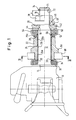
- a coupling body is designated 10.
- a tie rod 12 connects to this coupling body 10 in one piece.
- a support surface 14 is formed in the transition between the coupling body 10 and the pull rod 12.
- a threaded section 16 is formed, to which an outer cone 18 connects to the coupling body 10; this outer cone 18 merges into a cylindrical section 20 of the tie rod 12.
- the tie rod 12 is received by a tie rod bearing 22 in its cylindrical inner bore 24.
- a two-part chuck 26a, 26b is received between the inner bore 24 and the pull rod 12.
- the chuck part 26b has a radial flange 26c which bears against an end surface 28 of the tie rod bearing 22.
- a rubber spring is inserted, which is supported by a spring plate 34.
- the spring plate 34 sits on a centering collar 36 of the tie rod bearing 22.
- a clamping nut 38 is screwed onto the threaded section 16. This clamping nut 38 acts with a contact surface 40 against a contact surface 39 of a thrust washer 42.
- the thrust washer 42 has an inner cone 44, which is pressed by the clamping nut 38 against the outer cone 18 with pretension.
- the clamping nut 38 is designed with an annular groove 46, so that only the contact surface 40 rests against the thrust washer 42.
- a rubber spring 52 bears against the contact surface 50 of the thrust washer 42.
- This rubber spring 52 is supported by a spring plate 54 which is centered on a centering collar 56 of the lining part 26b.
- the rubber springs 32 and 52 are clamped together with their spring plates 34 and 54 and with the tie rod bearing 22 between the support surface 14 of the clutch body and the contact surface 50 of the pressure plate 42 under prestress.
- only a small part of the total force applied by the clamping nut 38 lies in the sequence of parts 32, 34, 22, 26c, 52, 54.
- the largest part of the tension applied is effective between the outer cone 18 and the clamping nut 38.
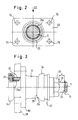
- a first ribbing 60 is attached to the contact surface 39 of the thrust washer 42 (FIG. 4), the profile of which can be seen from FIG. 7.
- a second ribbing 62 is attached to the inner cone 44, the profile of which also corresponds to FIG. 7.
- the ribs 60, 62 of the thrust washer 42 ensure a tight fit both on the outer cone 18 of the pull rod 12 and on the contact surface 39 of the nut 38.
- the nut 38 is also secured against rotation relative to the tie rod 12.
- the tie rod bearing 22 is provided with a mounting flange 66 which is connected to a carrier, i.e. with a cross member 68, is screwed by screws, which pass through holes 70 of the flange 66.
- the threaded section 16 is followed by an end section 71 of the pull rod 12.
- an annular groove 72 is incorporated at the end of the threaded section 16, which receives a locking ring 74 in the form of a simply divided and elastically expandable metal ring.
- This ring 74 is arranged at such a distance a from the clamping nut 38 that, if the clamping nut 38 is not expected to loosen, the rubber springs 32, 52 are substantially completely relaxed before the clamping nut 38 comes to rest against the locking ring 74. If this loosening has occurred, the tie rod 12 begins to shake axially and / or radially in the tie rod bearing 22.
- the locking ring 74 can be dimensioned as desired in its immersion depth in the end section 71 and in its axial width be without the necessary strength of the connection between the end portion 71 and tie rod 12 is impaired. Therefore, the securing ring 74 can in any case temporarily absorb the tensile forces occurring on the drawbar until the wobble is determined and remedial action taken after the next inspection at the latest. This is in contrast to securing with a split pin in conjunction with a tension nut designed as a crown nut.
- the locking ring 74 compared to a crown nut pin lock is that the locking ring 74 can not be subjected to any shear loads caused by torsion.
- the locking ring should be dimensioned in such a way that it offers a resistance of at least 700 Nm when the clamping nut is turned further.
Landscapes
- Engineering & Computer Science (AREA)
- Transportation (AREA)
- Mechanical Engineering (AREA)
- Mechanical Operated Clutches (AREA)
- Mutual Connection Of Rods And Tubes (AREA)
- Clamps And Clips (AREA)
Applications Claiming Priority (2)
| Application Number | Priority Date | Filing Date | Title |
|---|---|---|---|
| DE4015473A DE4015473A1 (de) | 1990-05-14 | 1990-05-14 | Anhaengerkupplung, stichwort: verliersicherung mit wackelabstand |
| DE4015473 | 1990-05-14 |
Publications (3)
| Publication Number | Publication Date |
|---|---|
| EP0457249A2 true EP0457249A2 (fr) | 1991-11-21 |
| EP0457249A3 EP0457249A3 (en) | 1993-01-20 |
| EP0457249B1 EP0457249B1 (fr) | 1995-09-06 |
Family
ID=6406380
Family Applications (1)
| Application Number | Title | Priority Date | Filing Date |
|---|---|---|---|
| EP91107736A Expired - Lifetime EP0457249B1 (fr) | 1990-05-14 | 1991-05-13 | Attelage de remorque mot clef: dispositif antiperte avec distance de sécurité |
Country Status (2)
| Country | Link |
|---|---|
| EP (1) | EP0457249B1 (fr) |
| DE (2) | DE4015473A1 (fr) |
Cited By (6)
| Publication number | Priority date | Publication date | Assignee | Title |
|---|---|---|---|---|
| DE102004045254B4 (de) * | 2004-09-17 | 2009-12-24 | Jost-Werke Gmbh & Co. Kg | Anhängerkupplung mit Zugstangenbefestigung |
| CN105711359A (zh) * | 2016-01-22 | 2016-06-29 | 安徽江淮汽车股份有限公司 | 一种牵引钩装置 |
| CN106696617A (zh) * | 2016-12-16 | 2017-05-24 | 约斯特(中国)汽车部件有限公司 | 牵引钩及牵引装置 |
| CN106739883A (zh) * | 2016-12-16 | 2017-05-31 | 约斯特(中国)汽车部件有限公司 | 牵引钩及牵引装置 |
| CN106739882A (zh) * | 2016-12-16 | 2017-05-31 | 约斯特(中国)汽车部件有限公司 | 牵引钩及牵引装置 |
| CN107053975A (zh) * | 2016-12-16 | 2017-08-18 | 约斯特(中国)汽车部件有限公司 | 牵引钩及牵引装置 |
Family Cites Families (6)
| Publication number | Priority date | Publication date | Assignee | Title |
|---|---|---|---|---|
| DE511434C (de) * | 1929-12-05 | 1930-10-30 | Rudolf Ernesti | Anhaengerkupplung fuer Kraftfahrzeuge |
| GB467185A (en) * | 1935-12-11 | 1937-06-11 | Reginald William Neate | Improvements in and relating to mountings for coupling devices |
| US3904226A (en) * | 1973-09-04 | 1975-09-09 | Carl J Smalley | Hitch |
| DE2732610C3 (de) * | 1977-07-19 | 1980-12-04 | Johann Rockinger Spezialfabrik Fuer Anhaengerkupplungen, 8000 Muenchen | Lagerung für eine Zugstange einer Anhängerkupplung |
| FR2568194B1 (fr) * | 1984-07-30 | 1989-05-26 | Lemoine Mecano Soudure | Systeme d'attelage a amortisseur. |
| DE3842271A1 (de) * | 1988-12-15 | 1990-06-28 | Rockinger Spezial Fab Joh | Anhaengerkupplung |
-
1990
- 1990-05-14 DE DE4015473A patent/DE4015473A1/de not_active Ceased
-
1991
- 1991-05-13 DE DE59106396T patent/DE59106396D1/de not_active Expired - Fee Related
- 1991-05-13 EP EP91107736A patent/EP0457249B1/fr not_active Expired - Lifetime
Cited By (8)
| Publication number | Priority date | Publication date | Assignee | Title |
|---|---|---|---|---|
| DE102004045254B4 (de) * | 2004-09-17 | 2009-12-24 | Jost-Werke Gmbh & Co. Kg | Anhängerkupplung mit Zugstangenbefestigung |
| CN105711359A (zh) * | 2016-01-22 | 2016-06-29 | 安徽江淮汽车股份有限公司 | 一种牵引钩装置 |
| CN105711359B (zh) * | 2016-01-22 | 2017-12-12 | 安徽江淮汽车集团股份有限公司 | 一种牵引钩装置 |
| CN106696617A (zh) * | 2016-12-16 | 2017-05-24 | 约斯特(中国)汽车部件有限公司 | 牵引钩及牵引装置 |
| CN106739883A (zh) * | 2016-12-16 | 2017-05-31 | 约斯特(中国)汽车部件有限公司 | 牵引钩及牵引装置 |
| CN106739882A (zh) * | 2016-12-16 | 2017-05-31 | 约斯特(中国)汽车部件有限公司 | 牵引钩及牵引装置 |
| CN107053975A (zh) * | 2016-12-16 | 2017-08-18 | 约斯特(中国)汽车部件有限公司 | 牵引钩及牵引装置 |
| CN106739882B (zh) * | 2016-12-16 | 2023-10-03 | 约斯特(中国)汽车部件有限公司 | 牵引钩及牵引装置 |
Also Published As
| Publication number | Publication date |
|---|---|
| EP0457249B1 (fr) | 1995-09-06 |
| DE59106396D1 (de) | 1995-10-12 |
| EP0457249A3 (en) | 1993-01-20 |
| DE4015473A1 (de) | 1991-11-21 |
Similar Documents
| Publication | Publication Date | Title |
|---|---|---|
| DE69522439T2 (de) | Blindbefestigungselement mit verformbarer hülse | |
| DE3831948C2 (fr) | ||
| EP0487890A1 (fr) | Jonction d'élément, en particulier d'un joint à brides | |
| EP0501149A1 (fr) | Serrure pour fixation d'un manchon d'accouplement | |
| EP3565976B1 (fr) | Dispositif de limitation de couple comportant trois brides | |
| EP3096963B1 (fr) | Attache de composant avec surface de support supportant les forces transversales | |
| DE102014008166A1 (de) | Hochfeste Befestigungsvorrichtung | |
| DE19906168C1 (de) | Konusschraubverbindung für Lamellenpaket-Wellenkupplungen | |
| DE3835543C1 (en) | Fastening element | |
| EP0457249B1 (fr) | Attelage de remorque mot clef: dispositif antiperte avec distance de sécurité | |
| DE102023207479A1 (de) | Vorrichtung zum Ausgleichen von Toleranzen | |
| EP0406801B1 (fr) | Dispositif de fixation | |
| DE102013213514A1 (de) | Sicherungsvorrichtung zum Sichern einer Mutter gegen ungewolltes Losdrehen, sowie Lageranordnung einer Welle | |
| WO2001038747A1 (fr) | Ecrou dote d'une rondelle | |
| DE10008597A1 (de) | Sicherungsaufbau für eine Mutter | |
| EP3736464A1 (fr) | Entretoise pour un agencement de fixation, agencement de fixation doté d'une telle entretoise ainsi que procédé de fixation d'une pièce de montage sur une pièce de support | |
| DE19944131B4 (de) | Klemmring | |
| DE10109660B4 (de) | Sicherungsring und Befestigungsvorrichtung für eine Welle-Nabe-Verbindung | |
| EP1277892B1 (fr) | Manchon pour lier des ronds à béton | |
| DE2139869A1 (de) | Befestigungselement | |
| DE3525948C2 (fr) | ||
| DE3410868A1 (de) | Wiederverwendbare formschluessige muttersicherung | |
| DE3610283A1 (de) | Gelenkverbindung | |
| DE3842271C2 (fr) | ||
| DE102009057389A1 (de) | Schraube |
Legal Events
| Date | Code | Title | Description |
|---|---|---|---|
| PUAI | Public reference made under article 153(3) epc to a published international application that has entered the european phase |
Free format text: ORIGINAL CODE: 0009012 |
|
| AK | Designated contracting states |
Kind code of ref document: A2 Designated state(s): CH DE ES FR IT LI NL SE |
|
| PUAL | Search report despatched |
Free format text: ORIGINAL CODE: 0009013 |
|
| AK | Designated contracting states |
Kind code of ref document: A3 Designated state(s): CH DE ES FR IT LI NL SE |
|
| 17P | Request for examination filed |
Effective date: 19930428 |
|
| 17Q | First examination report despatched |
Effective date: 19940617 |
|
| GRAA | (expected) grant |
Free format text: ORIGINAL CODE: 0009210 |
|
| AK | Designated contracting states |
Kind code of ref document: B1 Designated state(s): CH DE ES FR IT LI NL SE |
|
| PG25 | Lapsed in a contracting state [announced via postgrant information from national office to epo] |
Ref country code: ES Free format text: THE PATENT HAS BEEN ANNULLED BY A DECISION OF A NATIONAL AUTHORITY Effective date: 19950906 |
|
| ITF | It: translation for a ep patent filed | ||
| REF | Corresponds to: |
Ref document number: 59106396 Country of ref document: DE Date of ref document: 19951012 |
|
| ET | Fr: translation filed | ||
| PG25 | Lapsed in a contracting state [announced via postgrant information from national office to epo] |
Ref country code: LI Effective date: 19960531 Ref country code: CH Effective date: 19960531 |
|
| PLBE | No opposition filed within time limit |
Free format text: ORIGINAL CODE: 0009261 |
|
| STAA | Information on the status of an ep patent application or granted ep patent |
Free format text: STATUS: NO OPPOSITION FILED WITHIN TIME LIMIT |
|
| 26N | No opposition filed | ||
| REG | Reference to a national code |
Ref country code: CH Ref legal event code: PL |
|
| PGFP | Annual fee paid to national office [announced via postgrant information from national office to epo] |
Ref country code: NL Payment date: 20020430 Year of fee payment: 12 |
|
| PGFP | Annual fee paid to national office [announced via postgrant information from national office to epo] |
Ref country code: SE Payment date: 20020502 Year of fee payment: 12 |
|
| PGFP | Annual fee paid to national office [announced via postgrant information from national office to epo] |
Ref country code: DE Payment date: 20020511 Year of fee payment: 12 |
|
| PGFP | Annual fee paid to national office [announced via postgrant information from national office to epo] |
Ref country code: FR Payment date: 20020513 Year of fee payment: 12 |
|
| PG25 | Lapsed in a contracting state [announced via postgrant information from national office to epo] |
Ref country code: SE Free format text: LAPSE BECAUSE OF NON-PAYMENT OF DUE FEES Effective date: 20030514 |
|
| PG25 | Lapsed in a contracting state [announced via postgrant information from national office to epo] |
Ref country code: NL Free format text: LAPSE BECAUSE OF NON-PAYMENT OF DUE FEES Effective date: 20031201 |
|
| PG25 | Lapsed in a contracting state [announced via postgrant information from national office to epo] |
Ref country code: DE Free format text: LAPSE BECAUSE OF NON-PAYMENT OF DUE FEES Effective date: 20031202 |
|
| EUG | Se: european patent has lapsed | ||
| PG25 | Lapsed in a contracting state [announced via postgrant information from national office to epo] |
Ref country code: FR Free format text: LAPSE BECAUSE OF NON-PAYMENT OF DUE FEES Effective date: 20040130 |
|
| NLV4 | Nl: lapsed or anulled due to non-payment of the annual fee |
Effective date: 20031201 |
|
| REG | Reference to a national code |
Ref country code: FR Ref legal event code: ST |
|
| PG25 | Lapsed in a contracting state [announced via postgrant information from national office to epo] |
Ref country code: IT Free format text: LAPSE BECAUSE OF NON-PAYMENT OF DUE FEES;WARNING: LAPSES OF ITALIAN PATENTS WITH EFFECTIVE DATE BEFORE 2007 MAY HAVE OCCURRED AT ANY TIME BEFORE 2007. THE CORRECT EFFECTIVE DATE MAY BE DIFFERENT FROM THE ONE RECORDED. Effective date: 20050513 |