EP0487890A1 - Jonction d'élément, en particulier d'un joint à brides - Google Patents
Jonction d'élément, en particulier d'un joint à brides Download PDFInfo
- Publication number
- EP0487890A1 EP0487890A1 EP91117785A EP91117785A EP0487890A1 EP 0487890 A1 EP0487890 A1 EP 0487890A1 EP 91117785 A EP91117785 A EP 91117785A EP 91117785 A EP91117785 A EP 91117785A EP 0487890 A1 EP0487890 A1 EP 0487890A1
- Authority
- EP
- European Patent Office
- Prior art keywords
- clamping sleeve
- clamping
- component connection
- connection according
- bore
- Prior art date
- Legal status (The legal status is an assumption and is not a legal conclusion. Google has not performed a legal analysis and makes no representation as to the accuracy of the status listed.)
- Granted
Links
Images




Classifications
-
- F—MECHANICAL ENGINEERING; LIGHTING; HEATING; WEAPONS; BLASTING
- F16—ENGINEERING ELEMENTS AND UNITS; GENERAL MEASURES FOR PRODUCING AND MAINTAINING EFFECTIVE FUNCTIONING OF MACHINES OR INSTALLATIONS; THERMAL INSULATION IN GENERAL
- F16B—DEVICES FOR FASTENING OR SECURING CONSTRUCTIONAL ELEMENTS OR MACHINE PARTS TOGETHER, e.g. NAILS, BOLTS, CIRCLIPS, CLAMPS, CLIPS OR WEDGES; JOINTS OR JOINTING
- F16B21/00—Means for preventing relative axial movement of a pin, spigot, shaft or the like and a member surrounding it; Stud-and-socket releasable fastenings
- F16B21/06—Releasable fastening devices with snap-action
- F16B21/065—Releasable fastening devices with snap-action with an additional locking element
-
- F—MECHANICAL ENGINEERING; LIGHTING; HEATING; WEAPONS; BLASTING
- F16—ENGINEERING ELEMENTS AND UNITS; GENERAL MEASURES FOR PRODUCING AND MAINTAINING EFFECTIVE FUNCTIONING OF MACHINES OR INSTALLATIONS; THERMAL INSULATION IN GENERAL
- F16D—COUPLINGS FOR TRANSMITTING ROTATION; CLUTCHES; BRAKES
- F16D1/00—Couplings for rigidly connecting two coaxial shafts or other movable machine elements
- F16D1/02—Couplings for rigidly connecting two coaxial shafts or other movable machine elements for connecting two abutting shafts or the like
- F16D1/033—Couplings for rigidly connecting two coaxial shafts or other movable machine elements for connecting two abutting shafts or the like by clamping together two faces perpendicular to the axis of rotation, e.g. with bolted flanges
-
- F—MECHANICAL ENGINEERING; LIGHTING; HEATING; WEAPONS; BLASTING
- F16—ENGINEERING ELEMENTS AND UNITS; GENERAL MEASURES FOR PRODUCING AND MAINTAINING EFFECTIVE FUNCTIONING OF MACHINES OR INSTALLATIONS; THERMAL INSULATION IN GENERAL
- F16B—DEVICES FOR FASTENING OR SECURING CONSTRUCTIONAL ELEMENTS OR MACHINE PARTS TOGETHER, e.g. NAILS, BOLTS, CIRCLIPS, CLAMPS, CLIPS OR WEDGES; JOINTS OR JOINTING
- F16B19/00—Bolts without screw-thread; Pins, including deformable elements; Rivets
- F16B19/04—Rivets; Spigots or the like fastened by riveting
- F16B19/08—Hollow rivets; Multi-part rivets
- F16B19/10—Hollow rivets; Multi-part rivets fastened by expanding mechanically
- F16B19/1027—Multi-part rivets
- F16B19/1036—Blind rivets
- F16B19/1081—Blind rivets fastened by a drive-pin
-
- F—MECHANICAL ENGINEERING; LIGHTING; HEATING; WEAPONS; BLASTING
- F16—ENGINEERING ELEMENTS AND UNITS; GENERAL MEASURES FOR PRODUCING AND MAINTAINING EFFECTIVE FUNCTIONING OF MACHINES OR INSTALLATIONS; THERMAL INSULATION IN GENERAL
- F16B—DEVICES FOR FASTENING OR SECURING CONSTRUCTIONAL ELEMENTS OR MACHINE PARTS TOGETHER, e.g. NAILS, BOLTS, CIRCLIPS, CLAMPS, CLIPS OR WEDGES; JOINTS OR JOINTING
- F16B2200/00—Constructional details of connections not covered for in other groups of this subclass
- F16B2200/40—Clamping arrangements where clamping parts are received in recesses of elements to be connected
-
- F—MECHANICAL ENGINEERING; LIGHTING; HEATING; WEAPONS; BLASTING
- F16—ENGINEERING ELEMENTS AND UNITS; GENERAL MEASURES FOR PRODUCING AND MAINTAINING EFFECTIVE FUNCTIONING OF MACHINES OR INSTALLATIONS; THERMAL INSULATION IN GENERAL
- F16B—DEVICES FOR FASTENING OR SECURING CONSTRUCTIONAL ELEMENTS OR MACHINE PARTS TOGETHER, e.g. NAILS, BOLTS, CIRCLIPS, CLAMPS, CLIPS OR WEDGES; JOINTS OR JOINTING
- F16B2200/00—Constructional details of connections not covered for in other groups of this subclass
- F16B2200/50—Flanged connections
- F16B2200/506—Flanged connections bolted or riveted
-
- F—MECHANICAL ENGINEERING; LIGHTING; HEATING; WEAPONS; BLASTING
- F16—ENGINEERING ELEMENTS AND UNITS; GENERAL MEASURES FOR PRODUCING AND MAINTAINING EFFECTIVE FUNCTIONING OF MACHINES OR INSTALLATIONS; THERMAL INSULATION IN GENERAL
- F16D—COUPLINGS FOR TRANSMITTING ROTATION; CLUTCHES; BRAKES
- F16D3/00—Yielding couplings, i.e. with means permitting movement between the connected parts during the drive
- F16D3/16—Universal joints in which flexibility is produced by means of pivots or sliding or rolling connecting parts
- F16D3/26—Hooke's joints or other joints with an equivalent intermediate member to which each coupling part is pivotally or slidably connected
- F16D3/38—Hooke's joints or other joints with an equivalent intermediate member to which each coupling part is pivotally or slidably connected with a single intermediate member with trunnions or bearings arranged on two axes perpendicular to one another
- F16D3/382—Hooke's joints or other joints with an equivalent intermediate member to which each coupling part is pivotally or slidably connected with a single intermediate member with trunnions or bearings arranged on two axes perpendicular to one another constructional details of other than the intermediate member
- F16D3/387—Fork construction; Mounting of fork on shaft; Adapting shaft for mounting of fork
-
- Y—GENERAL TAGGING OF NEW TECHNOLOGICAL DEVELOPMENTS; GENERAL TAGGING OF CROSS-SECTIONAL TECHNOLOGIES SPANNING OVER SEVERAL SECTIONS OF THE IPC; TECHNICAL SUBJECTS COVERED BY FORMER USPC CROSS-REFERENCE ART COLLECTIONS [XRACs] AND DIGESTS
- Y10—TECHNICAL SUBJECTS COVERED BY FORMER USPC
- Y10T—TECHNICAL SUBJECTS COVERED BY FORMER US CLASSIFICATION
- Y10T403/00—Joints and connections
- Y10T403/49—Member deformed in situ
- Y10T403/4949—Deforming component is inserted section
-
- Y—GENERAL TAGGING OF NEW TECHNOLOGICAL DEVELOPMENTS; GENERAL TAGGING OF CROSS-SECTIONAL TECHNOLOGIES SPANNING OVER SEVERAL SECTIONS OF THE IPC; TECHNICAL SUBJECTS COVERED BY FORMER USPC CROSS-REFERENCE ART COLLECTIONS [XRACs] AND DIGESTS
- Y10—TECHNICAL SUBJECTS COVERED BY FORMER USPC
- Y10T—TECHNICAL SUBJECTS COVERED BY FORMER US CLASSIFICATION
- Y10T403/00—Joints and connections
- Y10T403/49—Member deformed in situ
- Y10T403/4966—Deformation occurs simultaneously with assembly
Definitions
- the invention relates to a component connection, in particular a flange connection for the connection of a fastening flange of a propeller shaft to the counter flange in a motor vehicle, with clamping elements arranged in mutually arranged and correspondingly arranged bores of the two flanges and supported on contact surfaces of the flanges.
- the clamping elements are designed as hollow rivets, the interlocking shafts of which are brought together by widening in a fixed contact. A targeted axial preload cannot be achieved in this way.
- FR-PS 70 34381 publication number 2 109 088
- a component connection is known in which a slotted clamping sleeve with a clamping bolt insertable therein is used as the clamping element.
- the adapter sleeve has a collar that bears against one of the components.
- the end of the adapter sleeve that protrudes through the holes in the components is brought into contact with the edge of the bore of the second component when the tensioning pin is inserted and is held in place by the conical design. A targeted axial preload cannot be achieved by this either.
- Screws are used to connect a mounting flange of a propeller shaft to the counter flange in a motor vehicle. These are intended to achieve a specific prestressing of the components to be connected to one another.
- the disadvantage of such a design is that the space available in the vehicle for installation is only small. Attaching the wrench, however, requires a certain amount of space. In addition, screw connections are not favorable for automation of the assembly.
- the invention is therefore based on the object of providing a flange connection in which a specific pretension can be achieved in automated assembly and which moreover requires only a small amount of space for assembly and permits a more compact design of the flanges.
- the clamping elements consist of an axially slotted clamping sleeve starting from their introducer and an insertable clamping pin therein that the clamping sleeve has a collar at its end facing away from the introducer, with its contact surface it is supported on a contact surface of the flange , and at the insertion end has a further collar with a support surface which, after radial expansion by the clamping bolt, bears against an abutment surface of the other flange, and that the free axial length of the clamping sleeve between the contact surface of the collar and the support surface of the further collar is smaller before assembly is the distance between the contact surface and the abutment surface of the adjacent flanges.
- the clamping sleeve When the clamping bolt is inserted, the clamping sleeve is in stretched to the desired dimensions in order to achieve the necessary preload. The clamping bolt remains in the clamping sleeve and thus prevents the connection from becoming loose.
- the slotted design allows an easy insertion of the clamping sleeve initially without the clamping bolt in order to achieve a pre-centering of the components to be connected. In normal cases, it is expedient to design the axial length so that it is a certain amount less than the distance between the flange contact surfaces, which corresponds at least to the elastic expansion and is below the elongation at break of the clamping sleeve.
- the support surface is inclined at an angle to the longitudinal axis of the locking sleeve, which deviates from the right angle.
- the angle is preferably 60 °.
- the abutment surface is also expediently also arranged with an inclination which corresponds to that of the support surface of the clamping sleeve.
- the clamping bolt is dimensioned shorter than the clamping sleeve.
- its length can also correspond to that of the adapter sleeve or can be made larger than the length thereof.
- clamping bolts that are the same length or longer than the clamping sleeve to provide them with a head.
- the clamping bolt is preferably secured against pulling out relative to the clamping sleeve by a locking ring. This can be achieved by providing a groove for the insertion of a locking ring for a clamping bolt with a head, at the end of which protrudes from the clamping sleeve after assembly.
- the retaining ring can be seated in the grooves of the adapter sleeve and locking pin.
- the clamping bolt is provided at its ends with locking lugs which, after passing through the bore of the clamping sleeve, bear against the end face of the clamping sleeve closest to the supporting surface.
- the clamping sleeve and the clamping bolt with a micro-toothing, which interlock after assembly.
- gluing is also conceivable.
- a combined formation of bonding and micro-toothing can also be represented.
- one of the components can be micro-serrated, while the other component contains a microencapsulated adhesive that is activated when the micro-serrated layer is reached.
- the counter flange has an annular edge in its bore towards the abutment surface.
- the clamping sleeve can be provided according to a further proposal to provide its outer section adjacent to the collar and into the bore of the flange with a thickening holding the adapter sleeve pre-assembled.
- the adapter sleeve is then pre-assembled on the flange, which facilitates final assembly with the counter flange.
- the clamping sleeve For dismantling, it is proposed to provide the clamping sleeve in its bore with an annular surface as a support base for an extrusion tool.
- the ring surface is arranged in the direction of the insertion of the clamping sleeve.
- the pressing takes place in the direction of the introducer.
- the segments of the clamping sleeve are acted upon by the extrusion tool until they tear off.
- the annular surface is part of a bore step starting from the collar of the clamping sleeve.
- the edge of the recess pointing towards the introduction and the clamping bolt can be used as a support base for the extrusion tool.
- the clamping bolt can also be provided with a continuous threaded hole in an embodiment of the invention.
- a screw for pulling out can be inserted into this.
- the pulling out of the clamping sleeve is further facilitated in that the clamping sleeve has a start-up shoulder on both sides in its bore for the retracted clamping bolt.
- Another alternative to breaking the connection is to destroy the adapter sleeve or the segments.
- the Clamping sleeve can be released by means of a mandrel which is pressed into the bore from the side of the collar and which destroys the segments.
- the adapter sleeve is provided with a tapered bore that runs through the collar and extends to the segments.
- Destruction of the segments can also be achieved by exerting a high tensile force on the clamping sleeve.
- the bore of the clamping sleeve in the region of the federal government is designed as a threaded bore for a pull-out pin.
- the segments can be destroyed by twisting the clamping sleeve.
- the collar of the clamping sleeve is designed as a hexagon key for attacking a key. Another key can be used to take the other fret.
- the segments are destroyed by turning the two bundles against each other using the attacking keys.
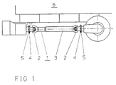
- FIG. 1 shows a propeller shaft 1 installed in a partially shown vehicle 6.
- This consists of two joints 2 which are arranged at a distance from one another and are connected to one another by an intermediate shaft 3.
- flanges 4 are attached, which are connected to corresponding counter flanges 5 of the vehicle drive train.
- one end of the propeller shaft 1 is connected to the counter flange 5, which is attached to the transmission output, while the flange 4 attached to the other end is connected to the counter flange 5 of the axle drive.
- the design of the flange connection is shown as detail Y on an enlarged scale in the further Figures 2 to 23 and explained below.
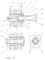
- the flange denoted by 4 which belongs to the propeller shaft 1, has a toothing 7 on a radial surface which engages with a corresponding counter toothing of the counter flange 5.
- the two flanges 4, 5 have circumferentially distributed bores 8, 9 which correspond to one another.
- an adapter sleeve 10 is inserted into the corresponding bores 8, 9.
- the clamping sleeve 10 has a bore 12 with the axis 11.
- the clamping sleeve 10 is provided with a collar 16 at one end. The other end is designed as an introductory 15.
- the clamping sleeve 10 is slotted for this purpose.
- the slots are designated 13.
- segments 14 are formed, which can spring onto the axis 11 when the clamping sleeve 10 is inserted into the bores 8, 9.
- a further collar 19 is attached, which has a larger outer diameter than the bore 9.
- This collar 19 is provided with a support surface 20 which, in the assembled state, as shown in FIG. 2 below, engages behind the flange 5 and rests with its support surface 20 on the abutment surface 21 of the flange 5.
- the collar 16 is also provided with a contact surface 17, which can be brought into contact with a contact surface 18 of the flange 4 when the clamping sleeve 10 is inserted into the bore 8, 9.
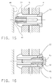
- the state during assembly can be seen from FIG. 2 above. It can be seen that the free length of the clamping sleeve 10 between the contact surface 17 and the support surface 20, which is denoted by L, is smaller than the distance between the two contact surfaces or the contact surface 18 of the flange 4 to the abutment surface 21 of the counter flange 5 , which is labeled X. From Figure 2 above it can be seen that a clamping bolt 22 is partially inserted into the bore 12 of the clamping sleeve 10.
- This clamping bolt 22 has an outer surface 26 with a diameter which is adapted to that of the bore 12. It has a head 23 at one end and a conical surface 25 at the other end.
- the introducer 19 or the segments 14 are shown spring-loaded onto one another. They are still inside the bore 9.
- the clamping bolt 22 is acted upon in the insertion direction, for example by a hydraulic tool, the clamping sleeve 10, in particular its segments 14, is progressively stretched over the cone surface 25 during insertion.
- the further collar 19 with the support surface 20 slides out of the bore 9 and is moved radially outward with its support surface 20 in contact with the abutment surface 21 in the further course of the insertion of the clamping bolt 22. It can be seen that the support surface 20 is arranged at an angle of inclination to the axis 11 which corresponds to the right angle. Due to the stretching, a prestress in the axial direction of the two flanges 4, 5 towards one another is achieved.
- the support surface 20 of the clamping sleeve 10 is not at right angles, but inclined at an acute angle to axis 11. An inclination with an angle of 60 ° is preferably provided.
- the abutment surface 21 is designed accordingly as a chamfer for the bore 9 of the flange 5. The stretching of the clamping sleeve 10 is facilitated by the oblique course when the clamping bolt 22 is pressed in. The press-in forces to achieve the desired preload are correspondingly lower.
- the difference in length is preferably designed such that an elongation lies in the range of the plastic deformation.
- Another advantage of the oblique course is that tolerances of dimension X can be bridged, with the desired prestress between the two flanges 4, 5.
- a further advantage is that after the pre-assembly of the clamping sleeve 10 but before the clamping bolt 22 is pressed in, the edge of the support surface 20a engages behind the edge 21a of the abutment surface 21 of the counter flange, thereby already axially fixing the flange 4 and counter flange 5. This is advantageous, for example, when mounting the cardan shaft in a motor vehicle.
- the resilient segments 14 can allow insertion by hand.
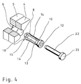
- the clamping bolt 22 does not have a head.
- the clamping bolt 22 only has conical surfaces 25 at its two ends.
- the length of the clamping bolt 22 corresponds to that of the clamping sleeve 10.
- FIG. 1 A further embodiment of the clamping bolt 22 is shown in FIG.
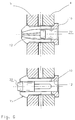
- the clamping bolt 22 has a length that is less than that of the clamping sleeve 10. It is advantageous that, for example, the bore 12 in the clamping sleeve 10 can be used to guide a tool for inserting the clamping bolt 22.
- the design of the clamping sleeve 10 corresponds to that described in connection with FIGS. 3 and 4.
- the clamping bolt 22 remains in the position shown below in FIG. 6 in order to support the collar, which is formed in the region of the insertion end 15 of the clamping sleeve 10, radially outwards.
- the deformation of the clamping sleeve 10 in the axial direction, ie its longitudinal expansion is preferably in the range of the plastic deformation, it is expedient that the clamping bolts 22 remain in the bore 12 of the clamping sleeve 10.
- Various securing options can be selected to secure their position under all operating conditions.
- Various examples are shown in Figures 7 to 11.
- a clamping bolt 22 which is axially longer than the clamping sleeve 10 that is to say axially protrudes therefrom in the assembled state
- securing is possible via a locking ring 27 which is inserted into a groove 24 in the clamping bolt 22.
- Fig. 7 a is another axial securing option of the clamping bolt 22 shown.
- the clamping bolt 22 is provided with a groove 24 in which a locking ring 27 is located.
- a groove 43 is also machined into the bore of the segments 14, in which the retaining ring 27 can spring open when the end position of the clamping bolt 22 is reached during the pressing in.
- a safety device as shown in FIG. 8 can also be used.
- the end of the clamping bolt 22 protruding from the clamping sleeve 10 is provided with one or more circumferentially distributed locking lugs 28 which can be supported axially on an end face 32 of the clamping sleeve 10.
- the bore 12 of the clamping sleeve 10 is provided with a slight indentation in which an adhesive layer 31 is embedded.
- a micro toothing 29 is provided in the bore 12 of the clamping sleeve 10 over a certain axial length in the area of the insertion end 15 and cooperates with a correspondingly positioned micro toothing 30 on the outer surface of the clamping bolt 22.
- the bore 12 of the clamping sleeve 10 is provided with a recess 33 in the region of the insertion end 15. Their axial length corresponds to that of the clamping bolt 22. After the clamping bolt 22 has been pressed in, the latter is latched between the shoulders 34 and 35 of the recess 33. This can be used for disassembly. By the action of a tool on the clamping bolt 22 in the direction of the introducer 15, this causes it to be supported against the shoulder 34 and, when a sufficiently large pressing force is exerted, tear off the segments 14 of the clamping sleeve 10.
- a bore step 36 is provided for dismantling the connection, which starts from the collar 16 and forms an annular surface 37 as a contact surface for the end face 39 of a pressing tool 38.
- FIG. 13 shows a further design option which enables the two flanges 4, 5 to be pre-fixed in relation to one another before the final connection is established by pressing the clamping bolts 22 into the bore of the clamping sleeve.
- the counter flange 5 starting from its abutment surface, is provided with a recess 40 which is larger in diameter than the bore 9 and which forms an annular edge 41 in the transition to the bore 9.
- This ring edge 41 can be used to bring about a provisional fixation and axial fixing of the clamping sleeve 10 with respect to the counter flange 5.
- the support surface 20 engages behind the ring edge 41 and holds the flange 4 and the counter flange 5 in an approximate axial contact with one another.
- FIG. 14 An alternative that enables the pre-assembly of the clamping sleeve 10 relative to the flange 4 can be seen in FIG. 14.
- the clamping sleeve 10 is enlarged on its outer surface adjoining the collar 16 with a thickening 42. With this thickening 42, the clamping sleeve 10 is fixed in the bore 8 of the flange 4.
- the thickened area 42 can extend both over the entire circumference of the clamping sleeve 10 and also over individual segments 14 in the form of humps.
- the clamping sleeve 10 is axially secured in the bore 8 of the flange 4 by pressing.
- the bracing can also be effected by partially pressing in the clamping bolt 22. During the final assembly, the clamping bolt is moved further in the direction of the introducer 15.
- the clamping bolt 22 is provided with a threaded bore 44, which enables the clamping bolt 22 to be pulled out of the clamping sleeve.
- This disassembly option has the advantage in limited space that the clamping bolt 22 does not have to be struck by the clamping sleeve 10.
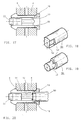
- 16 shows a possible disassembly of the clamping bolt 22, which was pulled into the shank region of the clamping sleeve 10 by means of a commercially available screw 45, the head 49 of which is supported against a support disk 46 lying against the collar 16. The clamping sleeve 10 can then be pulled out.
- the clamping sleeve 10 is provided with a conical bore 51, into which a stepped mandrel (Fig. 18/19) can penetrate and a support surface is created by chip formation in order to tear off the segments 14. (see Fig. 20).
- the mandrel 51 is graduated with at least one step 52, 53 so that a low squeezing force is achieved.
- the steps 52, 53 penetrate the segments 14 one after the other when they are pressed out and tear them off one after the other. As a result, only the tear-off force required for the segments 14 that are currently loaded is required.
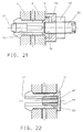
- Fig. 21 shows a disassembly option by destroying the segments 14.
- the clamping sleeve 10 is provided with an internal thread 54 into which a pull-out grub screw 55 can be screwed.
- a force which is generated by tightening a pull-out nut 57 can be supported via a bushing 56 until the segments 14 tear off and the clamping sleeve 10 is destroyed in order to disassemble the flanges 4 and 5.
- the clamping sleeve 10 is provided with a run-on shoulder 47 in the region of the bore 12 and the clamping bolt 22 is provided with a threaded bore 44.
- the threaded bore 44 in the clamping bolt 22 enables the clamping bolt 22 to to be withdrawn with the aid of a suitable dismantling tool to the start-up shoulder 47 of the clamping sleeve 10.
- a further pull on the clamping bolt 22 enables the clamping sleeve 10 to be pulled out and thus a dismantling of the flange connection.
- the collar 16 of the clamping sleeve 10 is provided with a suitable wrench surface 58 on which a commercially available tool, such as a ring spanner for hexagon screws, can engage.
- a key 59 as shown in the drawing on the right, can be placed on the collar 19 and is provided with lugs 60 which engage in the slots 13.
- a typical embodiment for such a flange connection the following dimensions are provided in millimeters (mm): X thickness of the two flanges 28 mm L length of the sleeve 27 mm Diameter of the clamping bolt 22 10 mm Bore of the adapter sleeve 10 10 mm Shaft / diameter of the adapter sleeve 15 mm Bore 8.9 of the flanges 17 mm Outside diameter of the collar 16 of the adapter sleeve 21 mm 41Cr4 can be used as a material.
Landscapes
- Engineering & Computer Science (AREA)
- General Engineering & Computer Science (AREA)
- Mechanical Engineering (AREA)
- Clamps And Clips (AREA)
- Mutual Connection Of Rods And Tubes (AREA)
- Connection Of Plates (AREA)
- Flanged Joints, Insulating Joints, And Other Joints (AREA)
- Insertion Pins And Rivets (AREA)
- Motor Power Transmission Devices (AREA)
Applications Claiming Priority (2)
| Application Number | Priority Date | Filing Date | Title |
|---|---|---|---|
| DE4034129 | 1990-10-26 | ||
| DE4034129A DE4034129C1 (fr) | 1990-10-26 | 1990-10-26 |
Publications (2)
| Publication Number | Publication Date |
|---|---|
| EP0487890A1 true EP0487890A1 (fr) | 1992-06-03 |
| EP0487890B1 EP0487890B1 (fr) | 1994-09-28 |
Family
ID=6417132
Family Applications (1)
| Application Number | Title | Priority Date | Filing Date |
|---|---|---|---|
| EP91117785A Expired - Lifetime EP0487890B1 (fr) | 1990-10-26 | 1991-10-18 | Jonction d'élément, en particulier d'un joint à brides |
Country Status (6)
| Country | Link |
|---|---|
| US (1) | US5259689A (fr) |
| EP (1) | EP0487890B1 (fr) |
| JP (1) | JP2552975B2 (fr) |
| AT (1) | ATE112368T1 (fr) |
| DE (1) | DE4034129C1 (fr) |
| ES (1) | ES2061146T3 (fr) |
Cited By (2)
| Publication number | Priority date | Publication date | Assignee | Title |
|---|---|---|---|---|
| WO1997013076A1 (fr) * | 1995-10-04 | 1997-04-10 | Deutsches Zentrum Für Luft- Und Raumfahrt | Procede et dispositif de transmission de forces entre deux pieces d'assemblage |
| EP0958957A1 (fr) * | 1998-05-16 | 1999-11-24 | Johnson Controls GmbH | Dispositif de retenue d'un siège de véhicule |
Families Citing this family (68)
| Publication number | Priority date | Publication date | Assignee | Title |
|---|---|---|---|---|
| JP2707011B2 (ja) * | 1991-11-26 | 1998-01-28 | 株式会社国盛化学 | 板状体の固着方法 |
| FR2697301B1 (fr) * | 1992-10-23 | 1995-01-13 | Socapex Amphenol | Dispositif de rivet à force d'insertion nulle. |
| US5848469A (en) * | 1996-09-26 | 1998-12-15 | The Budd Company | Vehicle frame with side/cross member joint |
| US6389684B1 (en) | 1997-05-05 | 2002-05-21 | Seagate Technology Llc | Swaging flexures to E-block arms |
| US6269532B1 (en) * | 1997-05-05 | 2001-08-07 | Seagate Technology Llc | Device for detaching swaged components in a disc drive |
| WO1999065409A1 (fr) * | 1998-06-10 | 1999-12-23 | Advanced Bypass Technologies, Inc. | Systemes d'anastomose sans suture |
| DE19840014C1 (de) * | 1998-09-02 | 1999-12-30 | Siemens Ag | Bauteil aus Kunststoff mit einem Spreizniet zur spielfreien Befestigung auf einer gelochten Platte |
| GB9822995D0 (en) * | 1998-10-22 | 1998-12-16 | Britax Wingard Ltd | Vehicle exterior mirror |
| US6238127B1 (en) * | 1998-12-17 | 2001-05-29 | Western Sky Industries, Inc. | Pivot apparatus including a fastener and bushing assembly |
| GB2347619B (en) * | 1999-03-10 | 2002-11-13 | Nmi Safety Systems Ltd | Improvements in or relating to a seat support |
| US6126663A (en) * | 1999-04-15 | 2000-10-03 | Hair; John Hunter | Expandable bone connector |
| WO2003001073A2 (fr) * | 2001-06-21 | 2003-01-03 | Black & Decker Inc. | Procede et appareil permettant de fixer une charpente metallique a l'aide de clous |
| WO2003001074A1 (fr) * | 2001-06-21 | 2003-01-03 | Black & Decker Inc. | Procede et appareil de fixation d'elements d'une structure en acier |
| AU2002315399A1 (en) * | 2001-06-21 | 2003-01-08 | Black And Decker Inc. | Method and apparatus for fastening steel framing by crimping |
| US7077613B2 (en) * | 2001-06-21 | 2006-07-18 | Black & Decker Inc. | Method and apparatus for fastening steel framing using helical features |
| US7008157B2 (en) * | 2001-06-21 | 2006-03-07 | Black & Decker Inc. | Explosive assisted expanding fastener |
| US20030047946A1 (en) * | 2001-09-07 | 2003-03-13 | Harout Ohanesian | Joint system for water well conduit assemblies |
| DE20115159U1 (de) * | 2001-09-13 | 2002-01-03 | Klann Tools Ltd., Didcot, Oxfordshire | Arretiervorrichtung für Motorwellen |
| ES2704151T3 (es) * | 2002-02-15 | 2019-03-14 | Centrix Inc | Sistema de anclaje de collar expansible |
| US6945728B2 (en) | 2002-06-07 | 2005-09-20 | Orchid Automation, Llc | Mechanical fastener |
| US7413424B2 (en) * | 2003-06-03 | 2008-08-19 | Brueninghaus Hydromatik Gmbh | Gear pump and holding element therefor |
| JP2005249111A (ja) * | 2004-03-05 | 2005-09-15 | Nifco Inc | 連結軸具、および、電子機器 |
| CN2770041Y (zh) * | 2004-12-22 | 2006-04-05 | 鸿富锦精密工业(深圳)有限公司 | 光盘驱动器 |
| US20080202179A1 (en) * | 2005-01-21 | 2008-08-28 | Nowicky David A | Lock Mechanism for an Enclosure and a Mold Device and Method for Forming a Lock Bore |
| DE202005005827U1 (de) * | 2005-04-11 | 2005-06-16 | Igus Gmbh | Gleitlager und Gleitlagersystem |
| US20070237605A1 (en) * | 2005-10-13 | 2007-10-11 | Northern Hydraulic Cylinder Engineers Limited | Pin |
| DE102006005183B4 (de) * | 2006-02-06 | 2014-12-24 | Robert Bosch Gmbh | Baueinheit mit einem Steuergerätegehäuse und einem Pumpengehäuse |
| JP4729445B2 (ja) * | 2006-06-27 | 2011-07-20 | トヨタ自動車株式会社 | 等速継手 |
| DE102007015590B3 (de) * | 2007-03-29 | 2008-10-02 | Zf Friedrichshafen Ag | Schwingungsdämpfer |
| US7686387B2 (en) * | 2007-08-28 | 2010-03-30 | Ford Global Technologies, Llc | Reinforcing sleeve for a tubular beam |
| GB0721325D0 (en) * | 2007-10-31 | 2007-12-12 | Rolls Royce Plc | fastener arrangements |
| AU2008100459B4 (en) * | 2008-05-19 | 2009-02-19 | Sandvik Intellectual Property Ab | A guide |
| DE102008032495A1 (de) | 2008-07-05 | 2010-01-07 | Daimler Ag | Kombination aus zwei Verrastungselementen zur Befestigung von Bauteilen mit definierter räumlicher Verschiebung |
| US8918974B2 (en) * | 2008-12-15 | 2014-12-30 | Michelin Recherche Et Technique S.A. | Method and apparatus for adjusting axle alignment |
| DE102009032682A1 (de) * | 2009-07-09 | 2011-01-13 | Läpple AG | Vorrichtung zum Verbinden mindestens zweier Teile |
| CN102192220B (zh) * | 2010-03-12 | 2014-12-24 | 鸿富锦精密工业(深圳)有限公司 | 锁扣装置 |
| TWI507613B (zh) * | 2010-04-13 | 2015-11-11 | Hon Hai Prec Ind Co Ltd | 鎖扣裝置 |
| GB201012987D0 (en) * | 2010-08-03 | 2010-09-15 | Airbus Operations Ltd | Single-sided fitting |
| US9367848B2 (en) | 2010-12-27 | 2016-06-14 | Stubhub, Inc. | Dynamic interactive seat map |
| US20130043714A1 (en) * | 2011-08-19 | 2013-02-21 | Raphael Schlanger | Vehicle wheel spoke connection |
| US9500218B2 (en) * | 2011-11-14 | 2016-11-22 | Illinois Tool Works Inc. | Anchoring fastener assembly |
| US9065307B2 (en) | 2012-08-03 | 2015-06-23 | Kohler Co. | Apparatus for facilitating attachment of fan and flywheel in an internal combustion engine |
| EP2906844B1 (fr) * | 2012-09-30 | 2021-05-05 | Saint-Gobain Performance Plastics Corporation | Ensemble de palier |
| US9297408B2 (en) * | 2014-01-30 | 2016-03-29 | GM Global Technology Operations LLC | Coupling spacer, assembly, and method |
| DE102014206255A1 (de) * | 2014-04-02 | 2015-10-08 | Mahle International Gmbh | Baugruppe mit Clipverbindung |
| FR3020098B1 (fr) * | 2014-04-22 | 2017-05-05 | A Raymond Et Cie | Dispositif de fixation par cramponnage |
| WO2016019920A1 (fr) * | 2014-08-08 | 2016-02-11 | 杨东佐 | Structure de liaison à fixation à expansion et procédé de liaison, et ensemble de liaison à fixation à expansion |
| WO2016019917A1 (fr) * | 2014-08-08 | 2016-02-11 | 杨东佐 | Ensemble de raccordement à fixation du type à contraction et expansion et structure de raccordement à fixation du type à contraction et expansion et procédé de raccordement |
| CN107076210B (zh) * | 2014-09-30 | 2019-09-17 | 株式会社Ihi | 轴承结构及增压器 |
| US10214861B2 (en) * | 2015-04-10 | 2019-02-26 | MOW Equipment Solutions, Inc. | Railway tie plate retention devices and methods to facilitate railway tie replacement |
| GB2533834B (en) * | 2015-07-17 | 2017-11-08 | Devetta Michael | Locator |
| JP6030196B1 (ja) * | 2015-08-07 | 2016-11-24 | 株式会社パックプラス | 口栓 |
| DE102015117784A1 (de) * | 2015-10-19 | 2017-04-20 | Kathrein-Werke Kg | Spreiznietverbindung und Verfahren zur Montage derselben |
| US11549538B2 (en) | 2018-04-12 | 2023-01-10 | Stephen M. Hill | Pressure lock retention fastener |
| DE102018205929A1 (de) * | 2018-04-18 | 2019-10-24 | Fidlock Gmbh | Befestigungsvorrichtung mit einem Basisteil und einem Sperrteil |
| DE102018129339A1 (de) * | 2018-11-21 | 2020-05-28 | Wittenstein Se | Einrichtung zur drehfesten Verbindung eines Verzahnungsteils mit einer Welle, Verfahren Herstellen einer solchen Einrichtung und Winkelgetriebe |
| CN110293492A (zh) * | 2019-06-28 | 2019-10-01 | 嘉兴迈拓精工科技有限公司 | 一种槽钢压板组合件 |
| CN110206802A (zh) * | 2019-07-05 | 2019-09-06 | 殷永升 | 一种自锁机械连接件 |
| WO2021231426A1 (fr) | 2020-05-12 | 2021-11-18 | Sky Climber Fasteners LLC | Dispositif de fixation de store |
| CN121993476A (zh) * | 2020-06-29 | 2026-05-08 | 酷码科技股份有限公司 | 结合组件 |
| US11795987B2 (en) | 2020-07-20 | 2023-10-24 | Bpc Lg 2, Llc | Rivetless nut plate |
| KR102234192B1 (ko) * | 2020-11-05 | 2021-04-01 | (주) 상용이엔지 | 편심 및 편각 동시 보상이 가능한 디스크 커플링 |
| CN112682104B (zh) * | 2020-12-25 | 2022-11-18 | 福建福清核电有限公司 | 一种核电厂汽轮机联轴器螺栓安装方法 |
| EP4119757A1 (fr) * | 2021-07-13 | 2023-01-18 | dormakaba Deutschland GmbH | Élément pour fixer thermiquement de maniere amovible, en particulier pour fixer un actionneur de porte |
| WO2023014964A1 (fr) | 2021-08-06 | 2023-02-09 | Sky Climber Fasteners LLC | Élément de fixation de panneau |
| EP4310347B1 (fr) * | 2022-07-21 | 2025-03-12 | Airbus Operations GmbH | Kit de pièces d'accouplement pour un agencement de montage pour monter une sous-structure intérieure sur une structure primaire d'un coussin d'air |
| US12276304B2 (en) * | 2022-12-07 | 2025-04-15 | Goodrich Corporation | Self-locking bushings |
| EP4467821A1 (fr) * | 2023-05-24 | 2024-11-27 | Airbus Operations GmbH | Élément de fixation ayant un corps qui est sélectivement extensible |
Citations (4)
| Publication number | Priority date | Publication date | Assignee | Title |
|---|---|---|---|---|
| DE2139869A1 (de) * | 1970-08-10 | 1972-02-17 | Vsi Corp | Befestigungselement |
| FR2109088A5 (fr) * | 1968-02-23 | 1972-05-26 | Mac Kenzie James | |
| DE2201186B2 (de) * | 1972-01-12 | 1975-04-24 | Brown, Boveri & Cie Ag, 6800 Mannheim | Aus Nieten gebildete mechanische Verbindung |
| DE2827031B2 (de) * | 1977-06-22 | 1980-10-09 | Hartwell Corp., Placentia, Calif. (V.St.A.) | Befestigungseinrichtung |
Family Cites Families (12)
| Publication number | Priority date | Publication date | Assignee | Title |
|---|---|---|---|---|
| US1131073A (en) * | 1914-08-05 | 1915-03-09 | Samuel M Mosher | Cross-head pin. |
| US1700354A (en) * | 1927-01-24 | 1929-01-29 | Merchant & Kilgore | Emergency rivet |
| US2941439A (en) * | 1957-01-30 | 1960-06-21 | Illinois Tool Works | Rivet and integral expander pin connected thereto by area of limited cross section |
| US3393599A (en) * | 1966-08-17 | 1968-07-23 | Illinois Tool Works | Fastening device |
| US3962843A (en) * | 1970-04-30 | 1976-06-15 | King John O Jun | Resilient sleeve joint construction |
| US4022536A (en) * | 1976-04-05 | 1977-05-10 | Caterpillar Tractor Co. | Hinge pin construction |
| FR2431060A1 (fr) * | 1978-07-13 | 1980-02-08 | Itw De France | Piece de fixation imperdable et reutilisable |
| US4405272A (en) * | 1981-03-11 | 1983-09-20 | Phillips Plastics Corporation | Two-piece fastener with front shoulder |
| JPS58130128U (ja) * | 1982-02-26 | 1983-09-02 | 日立造船株式会社 | 軸カツプリング結合治具 |
| DE3818464C1 (fr) * | 1988-05-31 | 1989-10-19 | Daimler-Benz Aktiengesellschaft, 7000 Stuttgart, De | |
| DE3927529C1 (fr) * | 1989-08-21 | 1991-03-07 | A. Raymond Kg, 7850 Loerrach, De | |
| US5065490A (en) * | 1990-05-31 | 1991-11-19 | Combustion Engineering, Inc. | Threaded insert for repairing a nuclear assembly |
-
1990
- 1990-10-26 DE DE4034129A patent/DE4034129C1/de not_active Expired - Lifetime
-
1991
- 1991-10-18 ES ES91117785T patent/ES2061146T3/es not_active Expired - Lifetime
- 1991-10-18 AT AT91117785T patent/ATE112368T1/de not_active IP Right Cessation
- 1991-10-18 EP EP91117785A patent/EP0487890B1/fr not_active Expired - Lifetime
- 1991-10-24 US US07/785,415 patent/US5259689A/en not_active Expired - Lifetime
- 1991-10-28 JP JP3307210A patent/JP2552975B2/ja not_active Expired - Lifetime
Patent Citations (4)
| Publication number | Priority date | Publication date | Assignee | Title |
|---|---|---|---|---|
| FR2109088A5 (fr) * | 1968-02-23 | 1972-05-26 | Mac Kenzie James | |
| DE2139869A1 (de) * | 1970-08-10 | 1972-02-17 | Vsi Corp | Befestigungselement |
| DE2201186B2 (de) * | 1972-01-12 | 1975-04-24 | Brown, Boveri & Cie Ag, 6800 Mannheim | Aus Nieten gebildete mechanische Verbindung |
| DE2827031B2 (de) * | 1977-06-22 | 1980-10-09 | Hartwell Corp., Placentia, Calif. (V.St.A.) | Befestigungseinrichtung |
Cited By (3)
| Publication number | Priority date | Publication date | Assignee | Title |
|---|---|---|---|---|
| WO1997013076A1 (fr) * | 1995-10-04 | 1997-04-10 | Deutsches Zentrum Für Luft- Und Raumfahrt | Procede et dispositif de transmission de forces entre deux pieces d'assemblage |
| US6045291A (en) * | 1995-10-04 | 2000-04-04 | Deutsches Zentrum Fuer Luft- Und Raumfahrt E.V. | Method and device for transmission of forces between two joined parts |
| EP0958957A1 (fr) * | 1998-05-16 | 1999-11-24 | Johnson Controls GmbH | Dispositif de retenue d'un siège de véhicule |
Also Published As
| Publication number | Publication date |
|---|---|
| US5259689A (en) | 1993-11-09 |
| EP0487890B1 (fr) | 1994-09-28 |
| ATE112368T1 (de) | 1994-10-15 |
| JPH051719A (ja) | 1993-01-08 |
| DE4034129C1 (fr) | 1992-05-07 |
| JP2552975B2 (ja) | 1996-11-13 |
| ES2061146T3 (es) | 1994-12-01 |
Similar Documents
| Publication | Publication Date | Title |
|---|---|---|
| EP0487890B1 (fr) | Jonction d'élément, en particulier d'un joint à brides | |
| DE69522439T2 (de) | Blindbefestigungselement mit verformbarer hülse | |
| DE19749219B4 (de) | Nicht-wiederabnehmbare Befestigungsvorrichtung | |
| DE2514799C2 (de) | Blindniet | |
| DE2008035B2 (de) | Blindniet | |
| EP0678679A1 (fr) | Elément à montage par rivetage dans une pièce en tôle | |
| EP0501149A1 (fr) | Serrure pour fixation d'un manchon d'accouplement | |
| EP1026416B1 (fr) | Raccord fileté cônique pour accouplement d'arbres au moyen de disques métalliques | |
| DE102023102863A1 (de) | Spreizbolzen, Verbindungsanordnung sowie Verfahren zum Erstellen einer solchen Verbindungsanordnung | |
| WO2018127336A1 (fr) | Dispositif de régulation de couple à trois organes de liaison | |
| DE69501636T2 (de) | Einsatzmutter und Befestigungselement | |
| EP1664564B1 (fr) | Systeme pour relier un arbre a une articulation | |
| EP0790423A1 (fr) | Méthode de fabrication d'un dispositif de connection pour des extrémités d'arbres cannelés destiné à la transmission d'un couple | |
| EP2484924A1 (fr) | Liaison bout à bout et procédé de développement d'une liaison bout à bout | |
| EP3074643B1 (fr) | Dispositif de fixation ajustable et procédé de fabrication d'un module préfabriqué à partir d'au moins un dispositif de fixation ajustable et d'une pièce | |
| DE4210488A1 (de) | Verbindungseinrichtung für ein insbesondere rohrförmiges Bauteil | |
| DE102009025151B4 (de) | Befestigungsanordnung und Verfahren zur Befestigung eines Schwungrads oder Schwungradteils an einer Kurbelwelle einer Brennkraftmaschine | |
| DE102013213514A1 (de) | Sicherungsvorrichtung zum Sichern einer Mutter gegen ungewolltes Losdrehen, sowie Lageranordnung einer Welle | |
| DE60026946T2 (de) | Mittel zum Andrücken einer Welle an einen Gabelkopf einer Lenkvorrichtung | |
| EP4495470B1 (fr) | Ecrou de boulon et son procede de fabrication | |
| DE102011014656A1 (de) | Befestigungseinheit | |
| EP3736464A1 (fr) | Entretoise pour un agencement de fixation, agencement de fixation doté d'une telle entretoise ainsi que procédé de fixation d'une pièce de montage sur une pièce de support | |
| DE19734539C2 (de) | Bauteilverbindung | |
| DE19912068B4 (de) | Wellen- oder Stellmutter und Verfahren zu ihrer Herstellung | |
| EP0457249B1 (fr) | Attelage de remorque mot clef: dispositif antiperte avec distance de sécurité |
Legal Events
| Date | Code | Title | Description |
|---|---|---|---|
| PUAI | Public reference made under article 153(3) epc to a published international application that has entered the european phase |
Free format text: ORIGINAL CODE: 0009012 |
|
| AK | Designated contracting states |
Kind code of ref document: A1 Designated state(s): AT BE DE ES FR GB IT NL SE |
|
| 17P | Request for examination filed |
Effective date: 19920507 |
|
| 17Q | First examination report despatched |
Effective date: 19930325 |
|
| RBV | Designated contracting states (corrected) |
Designated state(s): AT BE ES FR GB IT NL SE |
|
| REG | Reference to a national code |
Ref country code: DE Ref legal event code: 8566 |
|
| GRAA | (expected) grant |
Free format text: ORIGINAL CODE: 0009210 |
|
| AK | Designated contracting states |
Kind code of ref document: B1 Designated state(s): AT BE ES FR GB IT NL SE |
|
| REF | Corresponds to: |
Ref document number: 112368 Country of ref document: AT Date of ref document: 19941015 Kind code of ref document: T |
|
| ITF | It: translation for a ep patent filed | ||
| GBT | Gb: translation of ep patent filed (gb section 77(6)(a)/1977) |
Effective date: 19941019 |
|
| ET | Fr: translation filed | ||
| EAL | Se: european patent in force in sweden |
Ref document number: 91117785.5 |
|
| ITPR | It: changes in ownership of a european patent |
Owner name: FUSIONI;GKN AUTOMOTIVE AG |
|
| REG | Reference to a national code |
Ref country code: FR Ref legal event code: TP |
|
| REG | Reference to a national code |
Ref country code: ES Ref legal event code: PC2A Owner name: GKN AUTOMOTIVE AG |
|
| PLBE | No opposition filed within time limit |
Free format text: ORIGINAL CODE: 0009261 |
|
| STAA | Information on the status of an ep patent application or granted ep patent |
Free format text: STATUS: NO OPPOSITION FILED WITHIN TIME LIMIT |
|
| NLS | Nl: assignments of ep-patents |
Owner name: GKN AUTOMOTIVE AG |
|
| 26N | No opposition filed | ||
| REG | Reference to a national code |
Ref country code: GB Ref legal event code: 732E |
|
| PGFP | Annual fee paid to national office [announced via postgrant information from national office to epo] |
Ref country code: GB Payment date: 19960930 Year of fee payment: 6 |
|
| PGFP | Annual fee paid to national office [announced via postgrant information from national office to epo] |
Ref country code: FR Payment date: 19961016 Year of fee payment: 6 |
|
| PGFP | Annual fee paid to national office [announced via postgrant information from national office to epo] |
Ref country code: SE Payment date: 19961021 Year of fee payment: 6 Ref country code: BE Payment date: 19961021 Year of fee payment: 6 Ref country code: AT Payment date: 19961021 Year of fee payment: 6 |
|
| PGFP | Annual fee paid to national office [announced via postgrant information from national office to epo] |
Ref country code: NL Payment date: 19961029 Year of fee payment: 6 |
|
| PGFP | Annual fee paid to national office [announced via postgrant information from national office to epo] |
Ref country code: ES Payment date: 19961031 Year of fee payment: 6 |
|
| PG25 | Lapsed in a contracting state [announced via postgrant information from national office to epo] |
Ref country code: GB Free format text: LAPSE BECAUSE OF NON-PAYMENT OF DUE FEES Effective date: 19971018 Ref country code: AT Free format text: LAPSE BECAUSE OF NON-PAYMENT OF DUE FEES Effective date: 19971018 |
|
| PG25 | Lapsed in a contracting state [announced via postgrant information from national office to epo] |
Ref country code: SE Free format text: LAPSE BECAUSE OF NON-PAYMENT OF DUE FEES Effective date: 19971019 |
|
| PG25 | Lapsed in a contracting state [announced via postgrant information from national office to epo] |
Ref country code: ES Free format text: LAPSE BECAUSE OF THE APPLICANT RENOUNCES Effective date: 19971020 |
|
| PG25 | Lapsed in a contracting state [announced via postgrant information from national office to epo] |
Ref country code: FR Free format text: THE PATENT HAS BEEN ANNULLED BY A DECISION OF A NATIONAL AUTHORITY Effective date: 19971031 Ref country code: BE Free format text: LAPSE BECAUSE OF NON-PAYMENT OF DUE FEES Effective date: 19971031 |
|
| BERE | Be: lapsed |
Owner name: GKN AUTOMOTIVE A.G. Effective date: 19971031 |
|
| PG25 | Lapsed in a contracting state [announced via postgrant information from national office to epo] |
Ref country code: NL Free format text: LAPSE BECAUSE OF NON-PAYMENT OF DUE FEES Effective date: 19980501 |
|
| GBPC | Gb: european patent ceased through non-payment of renewal fee |
Effective date: 19971018 |
|
| NLV4 | Nl: lapsed or anulled due to non-payment of the annual fee |
Effective date: 19980501 |
|
| EUG | Se: european patent has lapsed |
Ref document number: 91117785.5 |
|
| REG | Reference to a national code |
Ref country code: FR Ref legal event code: ST |
|
| REG | Reference to a national code |
Ref country code: ES Ref legal event code: FD2A Effective date: 20001009 |
|
| PG25 | Lapsed in a contracting state [announced via postgrant information from national office to epo] |
Ref country code: IT Free format text: LAPSE BECAUSE OF NON-PAYMENT OF DUE FEES;WARNING: LAPSES OF ITALIAN PATENTS WITH EFFECTIVE DATE BEFORE 2007 MAY HAVE OCCURRED AT ANY TIME BEFORE 2007. THE CORRECT EFFECTIVE DATE MAY BE DIFFERENT FROM THE ONE RECORDED. Effective date: 20051018 |