EP0457376A2 - Crochet à rotation complète - Google Patents
Crochet à rotation complète Download PDFInfo
- Publication number
- EP0457376A2 EP0457376A2 EP91200401A EP91200401A EP0457376A2 EP 0457376 A2 EP0457376 A2 EP 0457376A2 EP 91200401 A EP91200401 A EP 91200401A EP 91200401 A EP91200401 A EP 91200401A EP 0457376 A2 EP0457376 A2 EP 0457376A2
- Authority
- EP
- European Patent Office
- Prior art keywords
- bobbin case
- bobbin
- cylindrical portion
- case holder
- holder
- Prior art date
- Legal status (The legal status is an assumption and is not a legal conclusion. Google has not performed a legal analysis and makes no representation as to the accuracy of the status listed.)
- Granted
Links
Images





Classifications
-
- D—TEXTILES; PAPER
- D05—SEWING; EMBROIDERING; TUFTING
- D05B—SEWING
- D05B57/00—Loop takers, e.g. loopers
- D05B57/08—Loop takers, e.g. loopers for lock-stitch sewing machines
- D05B57/10—Shuttles
- D05B57/14—Shuttles with rotary hooks
Definitions
- the present invention relates to a full rotary hook of a sewing machine.
- An object of the invention is to provide a full rotary hook which enables to increase the quantity of bobbin thread wound on a bobbin.
- Another object of the invention is to provide a full rotary hook which enables to increase the quantity of bobbin thread wound on a bobbin and to simplify the assembling operation of the constitution of installing the bobbin case by latching thereof in the bobbin case holder.
- Another object of the invention is to provide a full rotary hook which enables it to increase the quantity of bobbin thread wound on bobbin and to improve the sewing performance by making it possible for the looped needle thread to pass smoothly between the bobbin case holder rotation restraining notch and the rotation restraining member which is fitted in the notch.
- the invention provides a full rotary hook comprising; a bobbin case holder being increased a inner diameter which a portion in a circumferential direction of the bobbin case holder between a thread separating portion and a thread releasing portion being formed thinner than remainder portion in the circumferential direction.
- the invention provides a full rotary hook providing a bobbin case wherein an outward flange is formed to guide a needle thread loop and control slackness thereof to a small amount and a latch member installed freely movably in a radial direction of the bobbin case by guiding both sides of the latch member along a pair of opposing guide grooves of the bobbin case, thereby latching the latch member into a stud of a bobbin case holder characterized in that a portion near to flange of a guide portion which forms one guide groove on under side of a central axis of the bobbin case of the pair of guide grooves is recessed on other side so as to become far from another guide groove.
- the invention also provides a full rotary hook characterized in that a cylindrical portion of a bobbin case holder and a cylindrical portion of a bobbin case partially overlap on each other in an axial direction, and the cylindrical portion of the bobbin case is provided with an outward flange formed thereon to guide a needle thread loop and control its slackness to a small amount.
- the invention further provides a full rotary hook characterized in that a cylindrical portion of a bobbin case holder and a cylindrical portion of a bobbin case are partially overlapped in an axial direction, an end of the cylindrical portion of the bobbin case holder at upstream side in a hook body rotating direction and an end of the cylindrical portion of the bobbin case at downstream side in the hook body rotating direction being opposingly disposed near a rotation restraining notch of the bobbin case holder, and the end of the cylindrical portion of the bobbin case holder is located outside of an end of the cylindrical portion of the bobbin case in the radial direction.
- the bobbin in the bobbin case holder and moreover the inner diameter of the cylindrical portion which houses the bobbin case can be increased and thereby the outer diameter of the bobbin flange can be increased, thereby the quantity of bobbin thread wound on a bobbin drum can be increased.
- Thickness of the remainder portion in the circumferential direction of the bobbin case holder cylindrical portion is increased so that a desired strength can be obtained, and no needle thread exists between the outer periphery of the remainder in the circumferential direction of the bobbin case holder cylindrical portion and the inner periphery of the hook body. Therefore desired strength can be obtained as described above by increasing the thickness of the remainder of the circumferential portion.
- the quantity of bobbin thread wound on a bobbin drum can be increased without decreasing the strength of the bobbin case holder.
- the invention enables it to obtain sufficient strength of the bobbin case holder and at the same time to increase the quantity of bobbin thread wound on a bobbin drum.
- the cylindrical portion of the bobbin case holder and the cylindrical portion of the bobbin case are made to overlap on each other in the axial direction partially along the circumference, thereby it is enabled to make the inner diameter of the bobbin housing space of the bobbin case coincide with the inner diameter of the cylindrical portion of the bobbin case holder, so that the inner diameter of the bobbin case, and therefore the outer diameter of the bobbin flange can be increased.
- an outward flange is formed which guides the needle thread loop and controls the slackness to a small amount, to improve the sewing performance.
- both sides of the latch member which is freely movable in the radial direction of the bobbin case are guided along the pair of opposing guide groves of the bobbin case, thereby enabling it to latch the latch member at the end of the stud of the bobbin case holder, preventing the bobbin case from escaping from the bobbin case holder under the above conditions.
- the latch member When taking the bobbin case out of the bobbin case holder, the latch member is moved from the latched state to unlatch.
- the latch member is provided with a bent tail portion at its end, with the tail portion passing through a hole formed in the outward flange of the bobbin case and entering the inside of the bobbin case.
- the tail portion thereof holds the bobbin flange and therefore the bobbin case and the bobbin can be taken out together when taking out the bobbin case.
- the latch member has a spring receiving piece which projects outward on the side , with a spring being interposed between the spring receiving piece and the bobbin case holder, and the spring forces the latch member outwardly in the radial direction, namely in such a direction as to latch it.
- the latch member when fitting the latch member, whereon a tail portion which projects toward the inside of the bobbin case in formed, so that it is guided along the pair of guide grooves of the bobbin case, a part near to the hole of the guiding part which forms one guide groove is recessed on the side so that it becomes far from another guide groove, that is , the guiding part forming the one guide groove is partially broken away. Therefore, with the tail portion fitted in the hole, one side of the latch member including the spring receiving piece is exposed from the one guide groove and another side of the latch member where the spring receiving piece is not formed is fitted in the another guide groove, and it is possible to install the spring receiving piece in the bobbin case.
- the spring piece which projects outwardly on the side of the latch member can be moved while being fitted in one of the guide grooves, and therefore the latch member can be move stably along the guide groove.
- the cylindrical portion of the bobbin case holder and the cylindrical portion of the bobbin case are overlapped in the axial direction partially along the circumference and consequently outer diameter of the bobbin flange which is housed in the bobbin case can be increased near to the inner periphery of the bobbin case holder cylindrical portion, thereby enabling it to increase the quantity of bobbin thread wound around the bobbin.
- Fig.1 is a fragmentary perspective view of an embodiment of the invention.
- Fixed on a shaft 1 which is driven to rotate is a hook body 2 wherein a bobbins case holder 3 is housed, and a bobbin case 5 which houses a bobbin 4 is housed in the bobbin case holder 3.
- Fig.2 is a plan view of the bobbin case holder 3
- Fig.3 is a rear view of the bobbin case holder 3
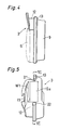
- Fig.4 is a side view of the bobbin case holder 3
- Fig.5 is a plan view of the bobbin case holder and
- Fig.6 is a sectional view of Fig.5 in the direction V1-V1.
- Cross portion of a horizontal axis full rotary hook which has such bobbin case holder 3 is shown in Fig.7.
- the bobbin 4 has a winding drum 7 of a straight cylinder shape whereon bobbin thread is wound, and flanges 8 which are fixed on both ends in the axial direction of the winding drum 7.
- a stud 10 which passes through the winding drum 7 of the bobbin 4.
- a bobbin case holder rib 13 which fits in a hook groove 14 formed in the hook body 2.
- a rotation restraining member 66 Fitted in a rotation restraining notch 15 of the bobbin case holder 3 is a rotation restraining member 66 which is fixed to the body of the sewing machine.
- the cylindrical portion 12 has the bobbin case holder rib 13 which has a thread hook portion 21 for the needle thread loop and a thread releasing portion 22 formed thereon.
- outer diameter of the flange 8 is increased.
- wall thickness of the cylindrical portion 12 of the bobbin case holder 3 must be decreased.
- thickness t1 of a part 12a in circumferential direction in W1 between the thread hook portion 21 and the thread releasing portion 22 is made less than the thickness t2 of the remainder portion 12b.
- Inner diameters of the portions 12a, 12b are uniform around the axial line of the stud 10, while the thickness t1 of the portion 12a is made less than the thickness t2 of the portion 12b of the remainder portion by ⁇ t in the peripheral portion. Because the needle thread exists in the zone W1 and thickness t1 is made smaller in the portion 12a, the needle thread does not receive undesirably large friction force in the space between the outer periphery of the portion 12a and the inner periphery of the hook body 2.
- the remainder portion 12b has thickness t2 which is enough to maintain the strength and therefore strength of the cylindrical portion 12 does not decrease.
- inner diameter 2R of the cylindrical portion 12 of the bobbin case holder 3 is made greater than the inner diameter of the conventional bobbin case holder by 0.6mm
- the outer diameter of the portion 12a is made equal to the outer diameter of the cylindrical portion of the conventional bobbin case holder
- outer diameter of the remainder portion 12b is made greater than the outer diameter of the cylindrical portion of the conventional bobbin case holder by 0.6mm.
- Fig.8 is a fragmentary perspective view of the bobbin case 5 of the invention
- Fig.9 is a front view showing the assembled condition of the bobbin case5.
- the cylindrical portion 12 of the bobbin case holder 3 and the cylindrical portion 23 of the bobbin case 5 overlap on each other in the axial direction (lateral direction in Fig.7) partially along the circumferential direction.
- An end 26 at the upstream in the hook body rotating direction 16 of the cylindrical portion 12 of the bobbin case holder 3 and the end 27 at the downstream in the hook body rotating direction 16 of the cylindrical portion 23 of the bobbin case 5 are opposingly disposed near the rotation restraining notch 15 of the bobbin case holder 3.
- an outward flange 29 is formed to guide the needle thread loop and control the slackness of the needle thread to a small amount.
- a pair of opposing guide grooves 31, 32 are formed by guide portions 33, 34.
- the guide grooves 31, 32 extend parallel in the radial direction of the bobbin case 5, and both sides of the latch member 35 are fitted in the guide grooves 31, 32 to be freely movable.
- Formed at the end of the latch member 35 is a bent tail portion 36 which passes through a hole 37 formed in the body 28 of the bobbin case 5 and enters the bobbin case 5 in the axial direction of the body 28.
- the hole 37 extends in the radial direction of the bobbin case 5.
- the tail portion 36 contacts the outer periphery of one of the flanges 8 which is disposed at the open end side of the bobbin 4, and works to take out the bobbin case 5 and the bobbin 4 at the same time, under the condition that the latter is locked in the former, from the bobbin case holder 3.
- a through hole 39 to form a hinge 38 therewith, by bending a part of the latch member 35.
- a through hole 41 to form the hinge 40 therewith, by bending the operating piece 40.
- a hinge pin 42 passes from one through hole 39 of the latch member 35 through the through hole 41 of the operating piece 40 and passes through another through hole 39, thereby the latch member 35 and the operating piece 40 are connected to be capable of making angular displacement around the axis of the hinge pin 42.
- Formed on the latch member 35 is a spring receiving piece 43 which projects outwardly on the side.
- the through hole 39, 41 of the hinge pin 42 are formed in the supports 44, 45.
- the latch member 35 has also a latch hole 46 formed therein in the longitudinal direction. An end 46a of the latch hole 46 is fastened in the small diameter 47 side formed at the end of the stud 10, to be in latched thereby. The latched status is released by the movement of the latch member 35.
- the guide groove 31 formed by the guide portion 33 is parallel to a diameter line 48 of the bobbin case 5.
- the guide portion 34 has a part 34a which is near the hole 37 and a part 34b which is far from the hole 37, and accordingly the guide groove 32 has a part 32a which is near the hole 37 and a part 32b which is far from the hole 37.
- the guide grooves 32a, 32b have a step 50 formed there between.
- Fig.10 is a sectional view of Fig.9 in the direction X-X.
- Installed in the guide groove 32a is a coil spring 51 one end thereof being in contact of the step 50 and other end thereof is in contact with the spring receiving piece 43.
- the spring 51 forces the latch member 35 in the direction of arrow 52 in Fig.9(1) and (2), namely outwardly in the radial direction of the body 28 of the bobbin case 5.
- the part 34a of the guide portion 34 near he hole 37 is formed by recessing sideways (rightward in Fig.9(1) and (2)) so that it is far from another guide groove 31.
- the operating piece 40 has a cam 54 formed at an end thereof.
- the cam 54 pulls the latch member 35 in the direction of an arrow 55 in Fig.12(1) against the force of the spring 51 as shown in Fig.12(1), when the operating piece 40 makes an angular displacement in the direction of an arrow 57a.
- the bobbin case 5 which houses the bobbin 4 is latched in the bobbin case holder 3, and escapement thereof is prevented.
- the operating piece 40 makes an angular displacement in the direction of an arrow 57.
- the spring 51 always gives the operating piece 40 a force to make an angular displacement in the direction of the arrow 57. Therefore in the condition shown in Fig.12(1), as shown in Fig.9(2), the spring receiving piece 43 is in the guide groove portion 32a and one side of the latch member 43 is in the guide groove portion 32b, another side of the latch member 35 is in the guide groove 31, and thereby the latch member 35 can stably move along the guide grooves 31, 32.
- the operating piece 40 When the operating piece 40 is released from a hand, the operating piece 40 make an angular displacement in the direction of the arrow 57 by the spring force of the spring 51, and makes an angular displacement from the state shown in Fig.12(3) to the state shown in Fig.12(4), with the end 46a of the latch hole 46 of the latch member 35 fastened in the small diameter latching portion 47 of the stud 10, entering latched state.
- the latch member 35 has a stopper 62 formed thereon. Displacement of the latch member 35 in the direction of an arrow 59 is restricted by the stopper 62 coming into contact with an end 37a of the hole 37.
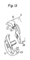
- Fig.13 is a perspective view of a part of the bobbin case holder 3 and the bobbin case 5.
- Fig.14 is a front view of the bobbin case holder 3 housing the bobbin case 5.
- the end 26 the bobbin case holder cylindrical portion 12 and the end 27 of the bobbin case 5 cylindrical portion 23 oppose to each other as described before.
- the end 26 of the bobbin case holder 3 cylindrical portion 12 is located at an outer position in the radial direction of the bobbin case holder 3 than the end 27 of the bobbin case 5 cylindrical portion 23, that is a step d1 is formed between the end 26 and the end 27.
- Fig.15 is an enlarged front view of the vicinity of the ends 26 and 27.
- the needle thread loop is in the condition as indicated by reference code 63 in Fig.14, where the needle thread loop is guided by the outward flange 29 and controlled so that slackness of the needle thread loop is decreased.
- the needle thread loop 63 is lifted by the upward motion of a thread take-up lever not shown in the figure to be in the condition indicated by the reference code 64, the needle thread passes over the outer periphery of the flange 29, and comes into contact with a part 26a of the end 26 which is exposed near the ends 26, 27.
- the needle thread 64 When the needle thread 64 is further pulled by the thread take-up lever in this condition, the needle thread passes through between the rotation restraining notch 15 of the bobbin case holder 3 and the rotation restraining member 66. In this manner, when the hook body 2 is rotating at a low speed, in particular, the needle thread loop 14 is hooked on the part 26a of the end 26 and then the needle thread 64 passes through between the rotation restraining notch 15 and the rotation restraining member 66. Therefore the motion of passing through is made smoothly without the needle thread being touching other parts or being caught, with the needle thread tension being stabilized, and the sewing performance can be improved.
- the ends 26, 27 are parallel to the direction of diameter 48 (refer to Fig.8) of the bobbin case holder 3.
- the end 26a formed on the bobbin case holder 3 may be formed in a shape which inclines to the rotation restraining notch 15 toward the outside in the radial direction as shown in Fig.16. This causes the needle thread 67 to be pulled smoothly through the end 26a as indicated by arrow 68, while the needle thread passes through between the rotation restraining notch 15 and the rotation restraining member 66 smoothly.
Landscapes
- Engineering & Computer Science (AREA)
- Textile Engineering (AREA)
- Sewing Machines And Sewing (AREA)
- Storage Of Web-Like Or Filamentary Materials (AREA)
Applications Claiming Priority (9)
| Application Number | Priority Date | Filing Date | Title |
|---|---|---|---|
| JP12636590A JPH0632735B2 (ja) | 1990-05-15 | 1990-05-15 | 全回転かま |
| JP12636590 | 1990-05-15 | ||
| JP126366/90 | 1990-05-15 | ||
| JP126364/90 | 1990-05-15 | ||
| JP12636490 | 1990-05-15 | ||
| JP126365/90 | 1990-05-15 | ||
| JP12636690A JPH0420376A (ja) | 1990-05-15 | 1990-05-15 | 全回転かま |
| JP12636490A JPH0420374A (ja) | 1990-05-15 | 1990-05-15 | 全回転かま |
| JP12636690 | 1990-05-15 |
Publications (3)
| Publication Number | Publication Date |
|---|---|
| EP0457376A2 true EP0457376A2 (fr) | 1991-11-21 |
| EP0457376A3 EP0457376A3 (fr) | 1991-12-18 |
| EP0457376B1 EP0457376B1 (fr) | 1999-08-04 |
Family
ID=27315313
Family Applications (1)
| Application Number | Title | Priority Date | Filing Date |
|---|---|---|---|
| EP91200401A Expired - Lifetime EP0457376B1 (fr) | 1990-05-15 | 1991-02-26 | Crochet à rotation complète |
Country Status (4)
| Country | Link |
|---|---|
| US (1) | US5109783A (fr) |
| EP (1) | EP0457376B1 (fr) |
| KR (1) | KR930003517B1 (fr) |
| DE (1) | DE69131493T2 (fr) |
Cited By (1)
| Publication number | Priority date | Publication date | Assignee | Title |
|---|---|---|---|---|
| US9797077B2 (en) | 2015-02-09 | 2017-10-24 | Cm Cerliani S.R.L. | Hook for lockstitch sewing machine comprising a bobbin case with a slide composed of multiple components |
Families Citing this family (11)
| Publication number | Priority date | Publication date | Assignee | Title |
|---|---|---|---|---|
| DE69130763T2 (de) * | 1991-07-25 | 1999-07-29 | Hirose Manufacturing Co. Ltd., Osaka | Nähmaschine |
| WO1993020273A1 (fr) * | 1992-03-31 | 1993-10-14 | Bakron Corporation | Broches renforcees comprenant un evidement destinees a des supports de canettes polymeres |
| US5651323A (en) * | 1994-02-24 | 1997-07-29 | Hirose Manufacturing Co., Ltd. | Hook assembly with coated surfaces for sewing machine |
| JP2742048B1 (ja) * | 1996-10-18 | 1998-04-22 | 株式会社廣瀬製作所 | 垂直全回転かま |
| TW370120U (en) * | 1997-01-29 | 1999-09-11 | Hirose Mfg Co Ltd | Sewing machine shuttle |
| US5921192A (en) * | 1998-01-22 | 1999-07-13 | Bakron Corporation | Bobbin assembly with structure for severing improperly routed thread |
| US6076477A (en) * | 1999-05-21 | 2000-06-20 | Badillo; Paul | Hook system for sewing machine |
| US6745712B1 (en) * | 1999-05-28 | 2004-06-08 | Mitsubishi Denki Kabushiki Kaisha | Fully rotatable shuttle |
| US6895296B2 (en) * | 2001-10-19 | 2005-05-17 | Kimberly-Clark Worldwide, Inc. | Spindle system, apparatus, and methods for applying spindle apparatus |
| KR100500827B1 (ko) * | 2004-07-05 | 2005-07-18 | 코베스트 주식회사 | 일부 개방형 보빈케이스 보디를 구비한 재봉틀의 회전북장치 |
| US7590467B2 (en) * | 2005-01-24 | 2009-09-15 | Kimberly-Clark Worldwide, Inc. | Spindle system, apparatus, and methods for applying spindle apparatus |
Family Cites Families (11)
| Publication number | Priority date | Publication date | Assignee | Title |
|---|---|---|---|---|
| US683847A (en) * | 1899-07-31 | 1901-10-01 | Emilio Catenacci | Revolving-hook machine. |
| US2098269A (en) * | 1937-01-02 | 1937-11-09 | Singer Mfg Co | Sewing machine shuttle |
| US2673541A (en) * | 1951-06-01 | 1954-03-30 | New Process Gear Corp | Rotary shuttle for sewing machines |
| BE572732A (fr) * | 1957-11-11 | |||
| US2974618A (en) * | 1958-09-12 | 1961-03-14 | Singer Mfg Co | Thread carriers for sewing machine loop takers |
| US2949874A (en) * | 1958-09-16 | 1960-08-23 | Singer Mfg Co | Thread carrier for sewing machine loop taker |
| US3199480A (en) * | 1962-10-19 | 1965-08-10 | Union Special Machine Co | Rotary hook construction |
| US3347193A (en) * | 1965-07-30 | 1967-10-17 | Union Special Machine Co | Semi-dull finish bobbin case basket |
| US3373707A (en) * | 1966-04-07 | 1968-03-19 | Singer Co | Loop taker for sewing machines |
| DE2028371A1 (de) * | 1969-06-09 | 1971-02-04 | Watanabe, Kenµ, Shibata (Japan) | Spulenkapsel fur Nähmaschinen |
| CA1307941C (fr) * | 1988-01-29 | 1992-09-29 | Michel Menard | Accelerometre attenuant la force d'une explosion |
-
1990
- 1990-12-28 KR KR1019900022097A patent/KR930003517B1/ko not_active Expired - Lifetime
-
1991
- 1991-02-26 DE DE69131493T patent/DE69131493T2/de not_active Expired - Lifetime
- 1991-02-26 EP EP91200401A patent/EP0457376B1/fr not_active Expired - Lifetime
- 1991-03-06 US US07/665,232 patent/US5109783A/en not_active Expired - Lifetime
Cited By (1)
| Publication number | Priority date | Publication date | Assignee | Title |
|---|---|---|---|---|
| US9797077B2 (en) | 2015-02-09 | 2017-10-24 | Cm Cerliani S.R.L. | Hook for lockstitch sewing machine comprising a bobbin case with a slide composed of multiple components |
Also Published As
| Publication number | Publication date |
|---|---|
| KR930003517B1 (ko) | 1993-05-01 |
| DE69131493T2 (de) | 2000-01-20 |
| US5109783A (en) | 1992-05-05 |
| DE69131493D1 (de) | 1999-09-09 |
| EP0457376B1 (fr) | 1999-08-04 |
| EP0457376A3 (fr) | 1991-12-18 |
| KR910020241A (ko) | 1991-12-19 |
Similar Documents
| Publication | Publication Date | Title |
|---|---|---|
| EP0457376A2 (fr) | Crochet à rotation complète | |
| US3797777A (en) | Tape reel and tape reel storing magazine | |
| EP0385297A2 (fr) | Crochet oscillant pour une machine à coudre | |
| US2851977A (en) | Loop takers for lock stitch sewing machines | |
| US3719330A (en) | Punched-tape unwinding device | |
| US3961763A (en) | Device for guiding a magnetic tape in a recording cassette | |
| US3856228A (en) | Tape reel | |
| JP2648442B2 (ja) | 全回転かま | |
| US20020080531A1 (en) | Electromagnetic linear actuator and tape drive using the same | |
| JPH0558759B2 (fr) | ||
| JPS59162079A (ja) | インクリボンカセツト | |
| US4236680A (en) | Take-up reel | |
| JPH0556997B2 (fr) | ||
| US5628471A (en) | Safety belt reeling device with safety belt guide designed for automatic assembly | |
| US4395103A (en) | Film winding device for camera | |
| US2098269A (en) | Sewing machine shuttle | |
| US4211373A (en) | Thread guiding system for sewing machine bobbin winders | |
| JPH0632735B2 (ja) | 全回転かま | |
| JP2824246B2 (ja) | ミシンのかま | |
| US3426977A (en) | Magnetic tape magazine | |
| JPH0642626Y2 (ja) | 垂直全回転かま | |
| US4217839A (en) | Adjustable anti-spill bobbin tension spring | |
| JP2568825Y2 (ja) | ミシンの全回転釜 | |
| JPH0420377A (ja) | 全回転かま | |
| US2743689A (en) | Sewing machine loop-takers |
Legal Events
| Date | Code | Title | Description |
|---|---|---|---|
| PUAI | Public reference made under article 153(3) epc to a published international application that has entered the european phase |
Free format text: ORIGINAL CODE: 0009012 |
|
| PUAL | Search report despatched |
Free format text: ORIGINAL CODE: 0009013 |
|
| AK | Designated contracting states |
Kind code of ref document: A2 Designated state(s): DE ES GB IT |
|
| AK | Designated contracting states |
Kind code of ref document: A3 Designated state(s): DE ES GB IT |
|
| 17P | Request for examination filed |
Effective date: 19920324 |
|
| 17Q | First examination report despatched |
Effective date: 19940318 |
|
| GRAG | Despatch of communication of intention to grant |
Free format text: ORIGINAL CODE: EPIDOS AGRA |
|
| GRAG | Despatch of communication of intention to grant |
Free format text: ORIGINAL CODE: EPIDOS AGRA |
|
| GRAH | Despatch of communication of intention to grant a patent |
Free format text: ORIGINAL CODE: EPIDOS IGRA |
|
| GRAH | Despatch of communication of intention to grant a patent |
Free format text: ORIGINAL CODE: EPIDOS IGRA |
|
| GRAA | (expected) grant |
Free format text: ORIGINAL CODE: 0009210 |
|
| AK | Designated contracting states |
Kind code of ref document: B1 Designated state(s): DE ES GB IT |
|
| PG25 | Lapsed in a contracting state [announced via postgrant information from national office to epo] |
Ref country code: ES Free format text: THE PATENT HAS BEEN ANNULLED BY A DECISION OF A NATIONAL AUTHORITY Effective date: 19990804 |
|
| REF | Corresponds to: |
Ref document number: 69131493 Country of ref document: DE Date of ref document: 19990909 |
|
| ITF | It: translation for a ep patent filed | ||
| PG25 | Lapsed in a contracting state [announced via postgrant information from national office to epo] |
Ref country code: GB Free format text: LAPSE BECAUSE OF NON-PAYMENT OF DUE FEES Effective date: 20000226 |
|
| PLBE | No opposition filed within time limit |
Free format text: ORIGINAL CODE: 0009261 |
|
| STAA | Information on the status of an ep patent application or granted ep patent |
Free format text: STATUS: NO OPPOSITION FILED WITHIN TIME LIMIT |
|
| 26N | No opposition filed | ||
| GBPC | Gb: european patent ceased through non-payment of renewal fee |
Effective date: 20000226 |
|
| PGFP | Annual fee paid to national office [announced via postgrant information from national office to epo] |
Ref country code: IT Payment date: 20100227 Year of fee payment: 20 |
|
| PGFP | Annual fee paid to national office [announced via postgrant information from national office to epo] |
Ref country code: DE Payment date: 20100303 Year of fee payment: 20 |
|
| REG | Reference to a national code |
Ref country code: DE Ref legal event code: R071 Ref document number: 69131493 Country of ref document: DE |
|
| PG25 | Lapsed in a contracting state [announced via postgrant information from national office to epo] |
Ref country code: DE Free format text: LAPSE BECAUSE OF EXPIRATION OF PROTECTION Effective date: 20110226 |