EP0457436A1 - Frein à disque pour un ascenseur - Google Patents
Frein à disque pour un ascenseur Download PDFInfo
- Publication number
- EP0457436A1 EP0457436A1 EP91303295A EP91303295A EP0457436A1 EP 0457436 A1 EP0457436 A1 EP 0457436A1 EP 91303295 A EP91303295 A EP 91303295A EP 91303295 A EP91303295 A EP 91303295A EP 0457436 A1 EP0457436 A1 EP 0457436A1
- Authority
- EP
- European Patent Office
- Prior art keywords
- brake
- levers
- arms
- shoes
- assembly
- Prior art date
- Legal status (The legal status is an assumption and is not a legal conclusion. Google has not performed a legal analysis and makes no representation as to the accuracy of the status listed.)
- Granted
Links
- 238000004140 cleaning Methods 0.000 claims description 3
- 238000010276 construction Methods 0.000 description 2
- 230000000712 assembly Effects 0.000 description 1
- 238000000429 assembly Methods 0.000 description 1
- WHGYBXFWUBPSRW-FOUAGVGXSA-N beta-cyclodextrin Chemical compound OC[C@H]([C@H]([C@@H]([C@H]1O)O)O[C@H]2O[C@@H]([C@@H](O[C@H]3O[C@H](CO)[C@H]([C@@H]([C@H]3O)O)O[C@H]3O[C@H](CO)[C@H]([C@@H]([C@H]3O)O)O[C@H]3O[C@H](CO)[C@H]([C@@H]([C@H]3O)O)O[C@H]3O[C@H](CO)[C@H]([C@@H]([C@H]3O)O)O3)[C@H](O)[C@H]2O)CO)O[C@@H]1O[C@H]1[C@H](O)[C@@H](O)[C@@H]3O[C@@H]1CO WHGYBXFWUBPSRW-FOUAGVGXSA-N 0.000 description 1
- 230000006835 compression Effects 0.000 description 1
- 238000007906 compression Methods 0.000 description 1
- 230000005611 electricity Effects 0.000 description 1
- 230000004907 flux Effects 0.000 description 1
Images


Classifications
-
- B—PERFORMING OPERATIONS; TRANSPORTING
- B66—HOISTING; LIFTING; HAULING
- B66D—CAPSTANS; WINCHES; TACKLES, e.g. PULLEY BLOCKS; HOISTS
- B66D5/00—Braking or detent devices characterised by application to lifting or hoisting gear, e.g. for controlling the lowering of loads
- B66D5/02—Crane, lift hoist, or winch brakes operating on drums, barrels, or ropes
- B66D5/24—Operating devices
- B66D5/30—Operating devices electrical
-
- B—PERFORMING OPERATIONS; TRANSPORTING
- B66—HOISTING; LIFTING; HAULING
- B66D—CAPSTANS; WINCHES; TACKLES, e.g. PULLEY BLOCKS; HOISTS
- B66D5/00—Braking or detent devices characterised by application to lifting or hoisting gear, e.g. for controlling the lowering of loads
- B66D5/02—Crane, lift hoist, or winch brakes operating on drums, barrels, or ropes
- B66D5/12—Crane, lift hoist, or winch brakes operating on drums, barrels, or ropes with axial effect
- B66D5/14—Crane, lift hoist, or winch brakes operating on drums, barrels, or ropes with axial effect embodying discs
-
- F—MECHANICAL ENGINEERING; LIGHTING; HEATING; WEAPONS; BLASTING
- F16—ENGINEERING ELEMENTS AND UNITS; GENERAL MEASURES FOR PRODUCING AND MAINTAINING EFFECTIVE FUNCTIONING OF MACHINES OR INSTALLATIONS; THERMAL INSULATION IN GENERAL
- F16D—COUPLINGS FOR TRANSMITTING ROTATION; CLUTCHES; BRAKES
- F16D55/00—Brakes with substantially-radial braking surfaces pressed together in axial direction, e.g. disc brakes
- F16D55/02—Brakes with substantially-radial braking surfaces pressed together in axial direction, e.g. disc brakes with axially-movable discs or pads pressed against axially-located rotating members
- F16D55/22—Brakes with substantially-radial braking surfaces pressed together in axial direction, e.g. disc brakes with axially-movable discs or pads pressed against axially-located rotating members by clamping an axially-located rotating disc between movable braking members, e.g. movable brake discs or brake pads
- F16D55/224—Brakes with substantially-radial braking surfaces pressed together in axial direction, e.g. disc brakes with axially-movable discs or pads pressed against axially-located rotating members by clamping an axially-located rotating disc between movable braking members, e.g. movable brake discs or brake pads with a common actuating member for the braking members
- F16D55/2245—Brakes with substantially-radial braking surfaces pressed together in axial direction, e.g. disc brakes with axially-movable discs or pads pressed against axially-located rotating members by clamping an axially-located rotating disc between movable braking members, e.g. movable brake discs or brake pads with a common actuating member for the braking members in which the common actuating member acts on two levers carrying the braking members, e.g. tong-type brakes
-
- F—MECHANICAL ENGINEERING; LIGHTING; HEATING; WEAPONS; BLASTING
- F16—ENGINEERING ELEMENTS AND UNITS; GENERAL MEASURES FOR PRODUCING AND MAINTAINING EFFECTIVE FUNCTIONING OF MACHINES OR INSTALLATIONS; THERMAL INSULATION IN GENERAL
- F16D—COUPLINGS FOR TRANSMITTING ROTATION; CLUTCHES; BRAKES
- F16D59/00—Self-acting brakes, e.g. coming into operation at a predetermined speed
- F16D59/02—Self-acting brakes, e.g. coming into operation at a predetermined speed spring-loaded and adapted to be released by mechanical, fluid, or electromagnetic means
-
- F—MECHANICAL ENGINEERING; LIGHTING; HEATING; WEAPONS; BLASTING
- F16—ENGINEERING ELEMENTS AND UNITS; GENERAL MEASURES FOR PRODUCING AND MAINTAINING EFFECTIVE FUNCTIONING OF MACHINES OR INSTALLATIONS; THERMAL INSULATION IN GENERAL
- F16D—COUPLINGS FOR TRANSMITTING ROTATION; CLUTCHES; BRAKES
- F16D65/00—Parts or details
- F16D65/38—Slack adjusters
- F16D65/40—Slack adjusters mechanical
- F16D65/42—Slack adjusters mechanical non-automatic
- F16D65/46—Slack adjusters mechanical non-automatic with screw-thread and nut
-
- F—MECHANICAL ENGINEERING; LIGHTING; HEATING; WEAPONS; BLASTING
- F16—ENGINEERING ELEMENTS AND UNITS; GENERAL MEASURES FOR PRODUCING AND MAINTAINING EFFECTIVE FUNCTIONING OF MACHINES OR INSTALLATIONS; THERMAL INSULATION IN GENERAL
- F16D—COUPLINGS FOR TRANSMITTING ROTATION; CLUTCHES; BRAKES
- F16D2121/00—Type of actuator operation force
- F16D2121/18—Electric or magnetic
- F16D2121/20—Electric or magnetic using electromagnets
- F16D2121/22—Electric or magnetic using electromagnets for releasing a normally applied brake
Definitions
- This invention relates to an improved brake assembly for use in holding an elevator car at a landing, which is also operable to stop the car under emergency conditions, as in a power failure or overspeed. More particularly, this invention relates to a caliper brake assembly for engagement with a disk secured to the elevator machine shaft or drive sheave to hold the latter against rotation.
- Disk brakes which act upon a disk secured to an elevator machine shaft to hold the elevator car in place at landings are known in the prior art.
- the disk brakes in the prior art adapted for elevator use are full plate disk brakes wherein the brake shoes are operable to engage the periphery of the disk to hold the car in place.
- Full plate disk brakes may be prone to dirt and moisture problems, and are not amenable to solenoid stroke variations due to their mode of operation. They are also noisy due to the difficulty in controlling motion in the relatively short stroke of the flat faced armature.
- This invention relates to a disk brake assembly for use in an elevator system wherein the disk brakes are caliper-type brakes which are operative to engage a brake disk mounted on the machine shaft or drive sheave to hold the car in place at landings. More particularly, the disk brake assembly of this invention comprises:
- the brake shoes are thus each spring biased on their mounts so that they will not tilt and drag on the brake disk when the brake is lifted.
- the assembly may also comprise a latching solenoid and plunger associated with levers that engage with the brake arms and may thus obtain a mechanical advantage whereby smaller solenoids can be used to hold the brake in an "off" condition.
- the plunger may have a larger stroke which provides the advantage of being able to control the noise of the plunger or core by stepping the solenoid plunger to bias the magnetic flux thus controlling the velocity and force of the plunger.
- the brake assembly of this invention may be spring-biased "on", so that when power to the solenoid is interrupted, the brake will engage the brake disk by reason of spring action.
- the spring action may be supplied to the brake shoes by a single spring, or each brake shoe can be biased independently by for example its own individual spring.
- the brake assembly may be modular whereby a number of the assemblies can be ganged on a single disk for heavier duty elevators.
- the construction of the brake may be such that some of its components and its solenoid can be repaired or cleaned after being detached from the assembly while the brake shoes engage the brake disk.
- Each module 2 includes a brake assembly 8 and a brake latch assembly 10.
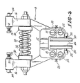
- FIGURES 1, 2 and 3 show details of the brake assembly 8.
- the brake assembly 8 includes a bracket 12 which is fixed to the machine frame or stand 14 (shown in phantom lines in FIGURES 1 and 2) and to which two opposed brake arms 16 are mounted for pivotal movement about pins 18.
- a brake shoe 20 is pivotally mounted on pins 22 to the brake arms 16 so as to flank the disk 4.
- a coil spring 24 sandwiched between each brake shoe 20 about its respective brake arm 16 biases each brake shoe 20 about its respective pin 22 and toward the inner end of an adjustable screw 23 threaded into each arm 16, such that the brake pads 26 on the shoes 20 remain parallel to each other and to the disk 4. In this manner the pads 26 are prevented from dragging on the disk 4 when the brake is lifted.
- a brake actuating spring 28 is mounted in spring caps 30 carried on spring guides 32 which are secured to the brake arms 16.
- the spring 28 biases the arms 16 outwardly about the pins 18 thereby biasing the brake shoes 20 against the disk 4. This action will occur whenever power is removed from the solenoid 36. In the event of a power failure or an emergency, the brake will automatically sit on the disk. The spring 28 thus supplies the force needed to set the brake.
- Cam pins 34 are mounted on the ends of the arms 16 distal of the brake shoes 20.
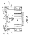
- FIGURES 1 and 4 show details of the brake latching assembly 10.
- the latch 10 includes a solenoid 36 fixed to the machine stand 14 and a solenoid actuated plunger 38 which moves up and down in the solenoid 36.
- Brackets 40 are mounted on opposite sides of the solenoid 36 and latch levers 42 with upturned fingers 43 are pivotally mounted on the brackets 40 via pins 44.
- a clevis 46 is disposed on the plunger 38 and receives overlapping ends 48 of the levers 42.
- a pin 50 spans the clevis 46 and overlies the ends 48 of the levers 42 thereby interconnecting the solenoid plunger 38 and the levers 42.
- the upturned fingers 43 on the levers 42 engage the cam pins 34 on the brake assembly 8.
- the plunger 38 When the solenoid 36 is supplied with electricity, the plunger 38 will be recessed in the solenoid 36, and the clevis 46, levers 42 and cam pins 34 will be in the positions shown in solid lines in FIGURE 4. The cam pins 34 will thus be latched causing compression of the brake actuating spring 28 and lifting the brake shoes 20 off the brake disk 4.
- the elevator controller switches off electrical power to the solenoid 36 allowing the plunger 38 and clevis 46 to rise to the position shown in phantom lines in FIGURE 4.
- a threaded bore 17 is formed to receive an adjustment bolt 19 carrying a lock nut 21.
- the bore 17 opens into a smooth bore 23 in which a pin 25 is slideably disposed.
- the pin 25 has rounded end walls 27 and 29 for providing point contact between the brake arms and levers and may carry a pair of friction rings 31 to snugly hold the pin 25 in place within the bore 23.
- the adjustment bolt 19 allows the pin 25 to move toward and away from finger 43 to thereby allow the positioning of the levers 42 to be modified.
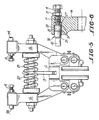
- FIGURE 5 there is shown an alternative embodiment of the invention wherein two actuating springs 27 and 29 are used, one for independently biasing each of the levers 16.
- Each of the springs 27 and 29 seats on a central plate 13 which is fastened to the bracket 12.
- the brake assembly of this invention provides several advantages over prior art caliper disk brakes. Biasing the brake shoes on the brake arms ensures that the brake shoes will not drag on the disk when the brakes are applied or lifted, thereby quieting the brake.
- the use of levers in the latch assembly provides the mechanical advantage sufficient to allow the use of a small latch solenoid having a longer stroke. The longer stroke solenoid allows the use of the stepped core whereby noise may be reduced.
- the use of two actuating springs on the brake assembly assures that spring failure will not completely prevent the brake from operating.
- the modular construction of the assembly enables one unit to be used in lighter duty elevators, and multiple units to be used in heavier duty elevators. It also allows repair and cleaning of the latch assembly components while the brake is set.
Landscapes
- Engineering & Computer Science (AREA)
- General Engineering & Computer Science (AREA)
- Mechanical Engineering (AREA)
- Physics & Mathematics (AREA)
- Electromagnetism (AREA)
- Braking Arrangements (AREA)
- Cage And Drive Apparatuses For Elevators (AREA)
Priority Applications (1)
| Application Number | Priority Date | Filing Date | Title |
|---|---|---|---|
| EP94203356A EP0641950B1 (fr) | 1990-04-13 | 1991-04-15 | Frein à disque pour un ascenseur |
Applications Claiming Priority (2)
| Application Number | Priority Date | Filing Date | Title |
|---|---|---|---|
| US50862790A | 1990-04-13 | 1990-04-13 | |
| US508627 | 1990-04-13 |
Related Child Applications (1)
| Application Number | Title | Priority Date | Filing Date |
|---|---|---|---|
| EP94203356.4 Division-Into | 1991-04-15 |
Publications (2)
| Publication Number | Publication Date |
|---|---|
| EP0457436A1 true EP0457436A1 (fr) | 1991-11-21 |
| EP0457436B1 EP0457436B1 (fr) | 1995-08-02 |
Family
ID=24023449
Family Applications (2)
| Application Number | Title | Priority Date | Filing Date |
|---|---|---|---|
| EP19910303295 Expired - Lifetime EP0457436B1 (fr) | 1990-04-13 | 1991-04-15 | Frein à disque pour un ascenseur |
| EP94203356A Expired - Lifetime EP0641950B1 (fr) | 1990-04-13 | 1991-04-15 | Frein à disque pour un ascenseur |
Family Applications After (1)
| Application Number | Title | Priority Date | Filing Date |
|---|---|---|---|
| EP94203356A Expired - Lifetime EP0641950B1 (fr) | 1990-04-13 | 1991-04-15 | Frein à disque pour un ascenseur |
Country Status (6)
| Country | Link |
|---|---|
| EP (2) | EP0457436B1 (fr) |
| JP (1) | JPH04226291A (fr) |
| AU (1) | AU624039B2 (fr) |
| CA (1) | CA2036363C (fr) |
| DE (2) | DE69111687T2 (fr) |
| ES (2) | ES2078439T3 (fr) |
Cited By (9)
| Publication number | Priority date | Publication date | Assignee | Title |
|---|---|---|---|---|
| DE19849749A1 (de) * | 1998-10-28 | 2000-05-04 | Mayr Christian Gmbh & Co Kg | Teilbelag-Federdruckbremse zum Angriff an einer rotierenden Scheibe |
| WO2009062164A3 (fr) * | 2007-11-08 | 2009-07-23 | Electronic Theatre Controls | Systèmes et procédés d'ensemble de levage |
| US7775506B2 (en) | 2006-04-28 | 2010-08-17 | Electronic Theatre Controls, Inc. | Lift assembly, system, and method |
| CN104370237A (zh) * | 2014-11-10 | 2015-02-25 | 巨人通力电梯有限公司 | 一种曳引机制动器 |
| US9061869B2 (en) | 2009-11-18 | 2015-06-23 | Electronic Theatre Controls, Inc. | Lift assembly systems and methods |
| CN109510389A (zh) * | 2017-09-15 | 2019-03-22 | 伊利诺斯工具制品有限公司 | 电磁电机的制动系统 |
| CN112268081A (zh) * | 2020-10-26 | 2021-01-26 | 河北翔金超环保科技有限公司 | 一种防偏磨电力液压制动器 |
| US11111117B2 (en) | 2012-12-21 | 2021-09-07 | Electronic Theatre Controls, Inc. | Compact hoist system |
| CN114132815A (zh) * | 2021-12-31 | 2022-03-04 | 中山天达电梯科技有限公司 | 一种家用电梯轿厢制动装置 |
Families Citing this family (10)
| Publication number | Priority date | Publication date | Assignee | Title |
|---|---|---|---|---|
| DE19719079C1 (de) * | 1997-04-30 | 1998-09-24 | Mannesmann Ag | Notaus-Stoppbremse für Krane |
| FI109788B (fi) * | 1998-06-08 | 2002-10-15 | Kone Corp | Vetopyörähissin pitojarru |
| DE10315985A1 (de) * | 2003-04-07 | 2004-10-28 | Bischoff Autofedern Und Nutzfahrzeugteile Gmbh | Feststellbremse |
| JP4932799B2 (ja) * | 2007-09-13 | 2012-05-16 | 曙ブレーキ工業株式会社 | アジャスタ機能付きパッドホルダ |
| JP2009208914A (ja) * | 2008-03-05 | 2009-09-17 | Toshiba Elevator Co Ltd | エレベータの縦振動抑制装置 |
| JP5361774B2 (ja) * | 2010-03-24 | 2013-12-04 | カヤバ工業株式会社 | キャリパブレーキ装置 |
| JP6018906B2 (ja) * | 2012-12-21 | 2016-11-02 | 株式会社日立製作所 | エレベータにおける巻上機用制動器 |
| JP2016034872A (ja) * | 2014-08-04 | 2016-03-17 | 株式会社日立製作所 | エレベータ用巻上機 |
| CN110831883B (zh) * | 2017-05-24 | 2021-02-02 | 三菱电机株式会社 | 电梯用曳引机 |
| WO2024112278A1 (fr) * | 2022-11-22 | 2024-05-30 | Ekdöksan Döküm Metal Otomoti̇v San. Ve Ti̇c. Ltd. Şti̇. | Système de centrage de disque d'armature pour frein d'ascenseur électromagnétique |
Citations (3)
| Publication number | Priority date | Publication date | Assignee | Title |
|---|---|---|---|---|
| GB869070A (en) * | 1956-10-27 | 1961-05-25 | Dunlop Rubber Co | Improvements in braking systems |
| DE2646736A1 (de) * | 1975-10-16 | 1977-04-28 | Fradisc Gagny Fa | Zange fuer scheibenbremsen |
| US4696377A (en) * | 1985-09-27 | 1987-09-29 | Ltv Energy Products Company | Brake system for drawworks |
Family Cites Families (2)
| Publication number | Priority date | Publication date | Assignee | Title |
|---|---|---|---|---|
| GB1094752A (en) * | 1964-02-22 | 1967-12-13 | J H Carruthers & Company Ltd | Improvements relating to disc brakes |
| GB1581829A (en) * | 1977-05-16 | 1980-12-31 | Wild & Co Ltd M B | Brake apparatus for a winding drum |
-
1991
- 1991-02-14 CA CA 2036363 patent/CA2036363C/fr not_active Expired - Fee Related
- 1991-03-15 AU AU73598/91A patent/AU624039B2/en not_active Ceased
- 1991-04-15 DE DE1991611687 patent/DE69111687T2/de not_active Expired - Fee Related
- 1991-04-15 EP EP19910303295 patent/EP0457436B1/fr not_active Expired - Lifetime
- 1991-04-15 DE DE1991625039 patent/DE69125039T2/de not_active Expired - Fee Related
- 1991-04-15 ES ES91303295T patent/ES2078439T3/es not_active Expired - Lifetime
- 1991-04-15 EP EP94203356A patent/EP0641950B1/fr not_active Expired - Lifetime
- 1991-04-15 JP JP3109847A patent/JPH04226291A/ja active Pending
- 1991-04-15 ES ES94203356T patent/ES2101433T3/es not_active Expired - Lifetime
Patent Citations (3)
| Publication number | Priority date | Publication date | Assignee | Title |
|---|---|---|---|---|
| GB869070A (en) * | 1956-10-27 | 1961-05-25 | Dunlop Rubber Co | Improvements in braking systems |
| DE2646736A1 (de) * | 1975-10-16 | 1977-04-28 | Fradisc Gagny Fa | Zange fuer scheibenbremsen |
| US4696377A (en) * | 1985-09-27 | 1987-09-29 | Ltv Energy Products Company | Brake system for drawworks |
Cited By (21)
| Publication number | Priority date | Publication date | Assignee | Title |
|---|---|---|---|---|
| DE19849749A1 (de) * | 1998-10-28 | 2000-05-04 | Mayr Christian Gmbh & Co Kg | Teilbelag-Federdruckbremse zum Angriff an einer rotierenden Scheibe |
| US7775506B2 (en) | 2006-04-28 | 2010-08-17 | Electronic Theatre Controls, Inc. | Lift assembly, system, and method |
| US8033528B2 (en) | 2006-04-28 | 2011-10-11 | Electronic Theatre Controls, Inc. | Lift assembly, system, and method |
| WO2009062164A3 (fr) * | 2007-11-08 | 2009-07-23 | Electronic Theatre Controls | Systèmes et procédés d'ensemble de levage |
| US8317159B2 (en) | 2007-11-08 | 2012-11-27 | Electronic Theatre Controls, Inc. | Lift assembly systems and methods |
| US8613428B2 (en) | 2007-11-08 | 2013-12-24 | Electronic Theatre Controls, Inc. | Lift assembly systems and methods |
| US10799809B2 (en) | 2007-11-08 | 2020-10-13 | Electronic Theatre Controls, Inc. | Lift assembly systems and methods |
| US10328358B2 (en) | 2007-11-08 | 2019-06-25 | Electronic Theatre Controls, Inc. | Lift assembly systems and methods |
| US9309094B2 (en) | 2007-11-08 | 2016-04-12 | Electronic Theatre Controls, Inc. | Lift assembly systems and methods |
| US9493328B2 (en) | 2007-11-08 | 2016-11-15 | Electronic Theatre Controls, Inc. | Lift assembly systems and methods |
| US10227221B2 (en) | 2009-11-18 | 2019-03-12 | Electronic Theatre Controls, Inc. | Lift assembly systems and methods |
| US9061869B2 (en) | 2009-11-18 | 2015-06-23 | Electronic Theatre Controls, Inc. | Lift assembly systems and methods |
| US10968085B2 (en) | 2009-11-18 | 2021-04-06 | Electronic Theatre Controls, Inc. | Lift assembly systems and methods |
| US11511978B2 (en) | 2009-11-18 | 2022-11-29 | Electronic Theatre Controls, Inc. | Lift assembly systems and methods |
| US11111117B2 (en) | 2012-12-21 | 2021-09-07 | Electronic Theatre Controls, Inc. | Compact hoist system |
| US11319198B2 (en) | 2012-12-21 | 2022-05-03 | Electronic Theatre Controls, Inc. | Compact hoist accessories and combination systems |
| CN104370237A (zh) * | 2014-11-10 | 2015-02-25 | 巨人通力电梯有限公司 | 一种曳引机制动器 |
| CN109510389A (zh) * | 2017-09-15 | 2019-03-22 | 伊利诺斯工具制品有限公司 | 电磁电机的制动系统 |
| CN109510389B (zh) * | 2017-09-15 | 2023-01-20 | 伊利诺斯工具制品有限公司 | 电磁电机的制动系统 |
| CN112268081A (zh) * | 2020-10-26 | 2021-01-26 | 河北翔金超环保科技有限公司 | 一种防偏磨电力液压制动器 |
| CN114132815A (zh) * | 2021-12-31 | 2022-03-04 | 中山天达电梯科技有限公司 | 一种家用电梯轿厢制动装置 |
Also Published As
| Publication number | Publication date |
|---|---|
| DE69125039T2 (de) | 1997-10-02 |
| AU624039B2 (en) | 1992-05-28 |
| EP0457436B1 (fr) | 1995-08-02 |
| ES2078439T3 (es) | 1995-12-16 |
| DE69125039D1 (de) | 1997-04-10 |
| AU7359891A (en) | 1991-10-17 |
| CA2036363C (fr) | 1999-08-24 |
| EP0641950A2 (fr) | 1995-03-08 |
| EP0641950B1 (fr) | 1997-03-05 |
| DE69111687D1 (de) | 1995-09-07 |
| ES2101433T3 (es) | 1997-07-01 |
| DE69111687T2 (de) | 1996-05-02 |
| EP0641950A3 (fr) | 1995-05-10 |
| JPH04226291A (ja) | 1992-08-14 |
| CA2036363A1 (fr) | 1991-10-14 |
Similar Documents
| Publication | Publication Date | Title |
|---|---|---|
| US5101939A (en) | Disk brake for elevator | |
| EP0457436B1 (fr) | Frein à disque pour un ascenseur | |
| JP4709650B2 (ja) | エレベータ用の遠隔リセット可能なロープ無し非常停止装置 | |
| CN103459290B (zh) | 电梯制动系统 | |
| US10889468B2 (en) | Electronics safety actuator | |
| US10562739B2 (en) | Synchronized electronic safety actuator | |
| JP5212971B2 (ja) | ブレーキ装置、エレベータ装置、ブレーキ装置の機能を検出するための方法、および最新化セット | |
| US6520299B2 (en) | Disk brake for elevator drive | |
| CN105164445B (zh) | 电磁式主动制动器 | |
| USRE38835E1 (en) | Remote brake release mechanism for an elevator machine | |
| EP0388299B1 (fr) | Dispositif d'arrêt pour des escaliers roulants | |
| CN1019566B (zh) | 用于电梯的安全盘式制动器 | |
| US6425462B1 (en) | Gravity-assisted elevator brake/clutch | |
| US5899304A (en) | Motor brake | |
| JP7558754B2 (ja) | 非常止め装置及びエレベーター | |
| US3525424A (en) | Electromagnetically released caliper brake | |
| EP4410727A1 (fr) | Dispositif d'ascenseur | |
| US11858781B2 (en) | Frictionless electronic safety actuator | |
| JPWO2002053485A1 (ja) | エレベータの非常ブレーキ装置 | |
| JPH0459585A (ja) | 巻上機のブレーキ解放装置 | |
| JPH0977396A (ja) | エレベータ用ブレーキ装置 | |
| HK40094202A (zh) | 控制电梯轿厢门的系统和翻新电梯轿厢门的方法 | |
| WO2024252060A1 (fr) | Engrenage de sécurité et agencement de sécurité pour un ascenseur et ascenseur | |
| CN118891216A (zh) | 制动拦截设备 | |
| WO2025191701A1 (fr) | Dispositif d'ascenseur |
Legal Events
| Date | Code | Title | Description |
|---|---|---|---|
| PUAI | Public reference made under article 153(3) epc to a published international application that has entered the european phase |
Free format text: ORIGINAL CODE: 0009012 |
|
| AK | Designated contracting states |
Kind code of ref document: A1 Designated state(s): DE ES FR GB IT |
|
| 17P | Request for examination filed |
Effective date: 19911204 |
|
| 17Q | First examination report despatched |
Effective date: 19930802 |
|
| GRAA | (expected) grant |
Free format text: ORIGINAL CODE: 0009210 |
|
| XX | Miscellaneous (additional remarks) |
Free format text: TEILANMELDUNG 94203356.4 EINGEREICHT AM 17.11.94. |
|
| ITF | It: translation for a ep patent filed | ||
| AK | Designated contracting states |
Kind code of ref document: B1 Designated state(s): DE ES FR GB IT |
|
| XX | Miscellaneous (additional remarks) |
Free format text: TEILANMELDUNG 94203356.4 EINGEREICHT AM 17.11.94. |
|
| REF | Corresponds to: |
Ref document number: 69111687 Country of ref document: DE Date of ref document: 19950907 |
|
| ET | Fr: translation filed | ||
| ITPR | It: changes in ownership of a european patent |
Owner name: ATTO DI LICENZA;OTIS S.P.A. - CALZOLARI ASCENSORE |
|
| REG | Reference to a national code |
Ref country code: ES Ref legal event code: FG2A Ref document number: 2078439 Country of ref document: ES Kind code of ref document: T3 |
|
| PLBE | No opposition filed within time limit |
Free format text: ORIGINAL CODE: 0009261 |
|
| STAA | Information on the status of an ep patent application or granted ep patent |
Free format text: STATUS: NO OPPOSITION FILED WITHIN TIME LIMIT |
|
| 26N | No opposition filed | ||
| PGFP | Annual fee paid to national office [announced via postgrant information from national office to epo] |
Ref country code: FR Payment date: 19980312 Year of fee payment: 8 |
|
| PGFP | Annual fee paid to national office [announced via postgrant information from national office to epo] |
Ref country code: ES Payment date: 19980415 Year of fee payment: 8 |
|
| PGFP | Annual fee paid to national office [announced via postgrant information from national office to epo] |
Ref country code: GB Payment date: 19990323 Year of fee payment: 9 |
|
| PG25 | Lapsed in a contracting state [announced via postgrant information from national office to epo] |
Ref country code: ES Free format text: LAPSE BECAUSE OF NON-PAYMENT OF DUE FEES Effective date: 19990416 |
|
| PG25 | Lapsed in a contracting state [announced via postgrant information from national office to epo] |
Ref country code: FR Free format text: LAPSE BECAUSE OF NON-PAYMENT OF DUE FEES Effective date: 19991231 |
|
| REG | Reference to a national code |
Ref country code: FR Ref legal event code: ST |
|
| PGFP | Annual fee paid to national office [announced via postgrant information from national office to epo] |
Ref country code: DE Payment date: 20000324 Year of fee payment: 10 |
|
| PG25 | Lapsed in a contracting state [announced via postgrant information from national office to epo] |
Ref country code: GB Free format text: LAPSE BECAUSE OF NON-PAYMENT OF DUE FEES Effective date: 20000415 |
|
| GBPC | Gb: european patent ceased through non-payment of renewal fee |
Effective date: 20000415 |
|
| REG | Reference to a national code |
Ref country code: ES Ref legal event code: FD2A Effective date: 20010503 |
|
| PG25 | Lapsed in a contracting state [announced via postgrant information from national office to epo] |
Ref country code: DE Free format text: LAPSE BECAUSE OF NON-PAYMENT OF DUE FEES Effective date: 20020201 |
|
| PG25 | Lapsed in a contracting state [announced via postgrant information from national office to epo] |
Ref country code: IT Free format text: LAPSE BECAUSE OF NON-PAYMENT OF DUE FEES;WARNING: LAPSES OF ITALIAN PATENTS WITH EFFECTIVE DATE BEFORE 2007 MAY HAVE OCCURRED AT ANY TIME BEFORE 2007. THE CORRECT EFFECTIVE DATE MAY BE DIFFERENT FROM THE ONE RECORDED. Effective date: 20050415 |