EP0457525A1 - Connecteur à bayonnette - Google Patents
Connecteur à bayonnette Download PDFInfo
- Publication number
- EP0457525A1 EP0457525A1 EP91304265A EP91304265A EP0457525A1 EP 0457525 A1 EP0457525 A1 EP 0457525A1 EP 91304265 A EP91304265 A EP 91304265A EP 91304265 A EP91304265 A EP 91304265A EP 0457525 A1 EP0457525 A1 EP 0457525A1
- Authority
- EP
- European Patent Office
- Prior art keywords
- securing ring
- securing
- bayonet connector
- cam
- shoulder
- Prior art date
- Legal status (The legal status is an assumption and is not a legal conclusion. Google has not performed a legal analysis and makes no representation as to the accuracy of the status listed.)
- Withdrawn
Links
- 239000004677 Nylon Substances 0.000 description 3
- 229920001778 nylon Polymers 0.000 description 3
- 238000010276 construction Methods 0.000 description 2
- 230000008878 coupling Effects 0.000 description 2
- 238000010168 coupling process Methods 0.000 description 2
- 238000005859 coupling reaction Methods 0.000 description 2
- 230000004048 modification Effects 0.000 description 2
- 238000012986 modification Methods 0.000 description 2
- 239000004033 plastic Substances 0.000 description 2
- 229920003023 plastic Polymers 0.000 description 2
- 238000005553 drilling Methods 0.000 description 1
- 238000002347 injection Methods 0.000 description 1
- 239000007924 injection Substances 0.000 description 1
- 239000002991 molded plastic Substances 0.000 description 1
- 230000000717 retained effect Effects 0.000 description 1
Images


Classifications
-
- H—ELECTRICITY
- H01—ELECTRIC ELEMENTS
- H01R—ELECTRICALLY-CONDUCTIVE CONNECTIONS; STRUCTURAL ASSOCIATIONS OF A PLURALITY OF MUTUALLY-INSULATED ELECTRICAL CONNECTING ELEMENTS; COUPLING DEVICES; CURRENT COLLECTORS
- H01R13/00—Details of coupling devices of the kinds covered by groups H01R12/70 or H01R24/00 - H01R33/00
- H01R13/62—Means for facilitating engagement or disengagement of coupling parts or for holding them in engagement
- H01R13/625—Casing or ring with bayonet engagement
Definitions
- This invention relates to a bayonet connector which can be used, for example, in joining an electrical plug and socket. However, it may be used for other purposes, e.g. joining hoses.
- a sensor on a vehicle gearbox which generates electrical pulses that are supplied, by a cable, to the tachograph itself where the pulses are processed in order to cause speed and distance traces to be drawn on a recording chart.
- the sensor includes a head which is fitted to a gearbox on the vehicle.
- An electrical plug and socket connects the head to the cable, the plug and socket being suitably coupled by means of a releasable coupling, such as a bayonet connector. This enables the components to be readily installed and maintained.
- the bayonet connector is also secured in its connected state, so that disconnection is impossible without breaking a component or a seal which would thereby indicate that some abuse has occurred.
- the present invention seeks to provide an effective lockable bayonet connector which can be more cheaply and easily mass produced.
- a bayonet connector comprises:
- a first part including a member having at least one cam track
- a second part including a member having at least one cam for engaging the cam track, the first and second members being connectable to make a bayonet connection, and
- a securing ring attached to the second member so that the second member is capable of independent rotation relative to the securing ring, the second member being rotatable between a releasing position, (where the first and second members can be disconnected) and a securing position, (where the first and second members are secured together), the securing ring having a cam or cams corresponding with the cam or cams on the second member, the arrangement being such that corresponding cams can be aligned when the second member is in its releasing position, and that said corresponding cams can be spaced apart when the second member is in its securing position; the first member having stops to limit the latter spacing and the second member and the securing ring having fastening means which cooperate to enable the second member to be secured in its securing position after said cams abut said stops and the bayonet connection has been made.
- the second cylindrical member and the securing ring can both be made of plastics, e.g. such as nylon, which is strong and resilient, and can be easily moulded.
- the securing ring is attached to the second member by snap connecting means.
- the second member may have an internal circumferential shoulder and the securing ring may have a plurality of resilient axial catches such as cantilevered arms with hooked portions at their free ends. These arms first flex to enable the locking ring to be fitted to the second member and the hooked portions then snap into position on the shoulder to retain the securing ring on the second member.
- resilient means on the second member such as integral arcuate portions overlying the shoulder, assist in securing the snap engagement of the axial catches on the shoulder.
- the securing ring can be quickly snap fitted into the second member to form an assembly which is part of a bayonet connector.
- the fastening means on the second member and on the securing ring additionally enable these two components to be securely fastened together thereby peventing reverse relative rotation which would otherwise enable the first and second members to be disconnected.
- Such fastening means may be constructed so that elements, such as apertured lugs, are aligned on both the second member and the securing ring when the second member is in its securing position. This enables a wire to be passed through the apertured lugs and secured to a seal.
- fastening means may be employed to ensure that the second member and the securing ring cooperate to enable the second member to be fastened in its securing position.
- Such means may be provided, for example, on the interior of the second member, e.g. where a cam or catch moves into a locking position when the second member is turned into its securing position.
- Such fastening means may not be accessible from the exterior. In this case, the fastening means may be released, for example, by breaking the cam, catch or a frangible stop or by drilling the connector to remove such components or by removing a seal to gain access, all of which indicate that an abuse has occurred.
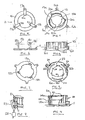
- a first cylindrical member 1 which is part of a plastics electrical socket, is provided with three cam tracks 2 (only one of which is visible).
- Each cam track 2 has an axially directed portion 3 and a circumferentially directed portion 4.
- Axial portion 3 has an open end 5 and a closed end 6 in the form of a shallow recess in a shoulder portion 7 of member 1.
- Circumferential portion 4 has an open end 8a and a closed end 8b.
- a chamfered portion 9 acts as a ramp to facilitate making the bayonet connection as will be described below.
- the device illustrated in Fig. 9 is a sensing head which is fitted to the gearbox of a vehicle. As it is of generally known construction, no further details need be described (since only an understanding of the cam track 2 is necessary to the present invention).
- second cylindrical member 10 and a securing ring 11 are assembled together, in use, to form a second part of the bayonet connection.
- the second member 10 has a generally cylindrical body 12 with three radially inwardly directed cams 13a, 13b and 13c. These cams are received initially by the open ends of the axial portions 3 of the grooves 2 (Fig. 9) and subsequently by circumferential portions 4 of the grooves 1 due to the push and twist fitting of member 19 on member 1.
- Chamfered portion 9 helps to guide cams 13a, 13b and 13c into the circumferential portions of the cam track thereby drawing members 1 and 10 more closely together, as member 10 is twisted relative to member 1.
- Corresponding cams 14a, 14b and 14c extend radially inwardly of an annular disc shaped body 15 of the securing ring 11. These cams 14a, 14b and 14c, when aligned with cams 13a, 13b and 13c (as shown in Fig. 10) also enter the axial portion of the camming groove when the members 1 and 10 are fitted together. However, cams 14a, 14b and 14c are retained in the recesses 6 so that when member 10 is twisted, only cams 13a, 13b and 13c rotate, relative to the stationary securing ring 11, into the circumferential portions 4 where they abut the closed ends 8b of the circumferential portions 4 of each groove 2 (Fig. 11).
- apertured lugs 16a, 16b, and 16c on member 10 are aligned with similar apertured lugs 17a, 17b and 17c on the securing ring 11 whereby a wire 27 can be passed through the apertures 21, and its ends can be twisted together and secured to, e.g. a crimped seal 28 as shown in Fig. 8.
- This wire 27 prevents relative rotation of a member 10 and securing ring 11 so that the bayonet connection is securely fastened. Only when the wire is cut and removed, can member 10 be twisted back to its "releasing position" where the aligned cams (13a, 14a in Fig. 10) can then be withdrawn through the axial portion 3 of the cam groove.
- Securing ring 11 can be fitted to member 10 by first introducing the free ends of cantilevered arms 18a, 18b and 18c into the interior of member 10. Each free end of these arms terminates in a hooked portion 19a, 19b and 19c which has an inclined face that is guided by chamfered grooves 20a, 20b and 20c into the body 12 of member 10 when the securing ring 11 is fitted thereto.
- the arms 18a, 18b, and 18c therefore first flex inwardly as portins 19a, 19b, 19c ride over the corresponding grooved wall portion of the body 12 before they snap into position and thereby engage a circumferential shoulder 22 as shown in the part cross-sectional elevational view of the assembly shown in Fig. 4. (Fig.
- Fig. 9 also illustrates a small prominence or cam 26 on the side wall of the circumferentially directed groove portion 4 which provides a kind of over-centre action as the assembly of the securing ring 11 and member 10 is twisted relative to member 1 in order to make the bayonet connection.
- cams 13a, 13b and 13c move arcuately around the circumferential portions 4 of the groove 2, they engage with the respective prominences 26.
- the structure of member 10 (which may be made of nylon) is such as to enable some resilient deflection to occur as the cams 13a, 13b, 13c are rotated towards their final position where they abut the end walls 8 of the circumferential groove portions 4 which act as stops.
- the cams 13a, 13b, 13c therefore need to be squeezed into their final position whereby the final twisting action is-one which requires sufficient force to achieve the "securing position" of member 10, hence ensuring a tight fit of the member 10 when on member 1 when the bayonet connection is made.
- the apertured lugs (16a, 17a in Fig. 10) are then aligned in order to enable the wire to be inserted and its ends sealed together. This ensures that the bayonet connection is securely fastened.
- Figs. 10-13 schematically illustrate the relative position of the cams (13, 14) and the apertured lugs (16, 17) in releasing and securing positions of member 10. Only one pair of cams has been illustrated (in Figs. 10 and 11) to show the operation of the bayonet connector.
- Figs. 12 and 13 are also schematic underside views to show how the cams (13, 14) align (Fig. 12) and the lugs align (Fig. 13).
- the member 10 and securing ring 11 may be made of nylon which is strong, durable and resilient.
- Member 1, which is of conventional construction can be made of an injection moulded plastics which has sufficient strength and rigidity.
- the bayonet connector of the preferred embodiment is used to join an electrical plug and socket (not shown).
- a cable sleeve 30 (Fig. 9) having an outwardly directed circular flange (not shown) is fitted to member 10 before the securing ring 11 is snap fitted.
- the bayonet connector of the invention has other uses, for example, it can be used to connect hoses together.
- a hidden detent or detents within the body 12, may engage a stop surface or surfaces on the annular portion 15 of the ring 11 so that when member 10 is twisted, the detent or detents snap into position over the respective stop surfaces, when member 10 is in its securing position, thereby fastening member 10 to member 11.
- Such detents may be inaccessible so that member 10 must be cut, e.g. with a special tool, in order to release the connection.
- the detent or detents may be only accessible by a special tool, or after removing a special covering seal (not shown), in the body 12, so that the detents could be released whereby the parts of the bayonet fitting can be disconnected.
- Fig. 14 also shows a modification in the form of three recesses 31 (only one of which is shown) in member 10 which are provided to facilitate tooling so that a constant wall thickness can be maintained.
Landscapes
- Quick-Acting Or Multi-Walled Pipe Joints (AREA)
Applications Claiming Priority (2)
| Application Number | Priority Date | Filing Date | Title |
|---|---|---|---|
| GB9011036 | 1990-05-16 | ||
| GB909011036A GB9011036D0 (en) | 1990-05-16 | 1990-05-16 | Bayonet connector |
Publications (1)
| Publication Number | Publication Date |
|---|---|
| EP0457525A1 true EP0457525A1 (fr) | 1991-11-21 |
Family
ID=10676123
Family Applications (1)
| Application Number | Title | Priority Date | Filing Date |
|---|---|---|---|
| EP91304265A Withdrawn EP0457525A1 (fr) | 1990-05-16 | 1991-05-13 | Connecteur à bayonnette |
Country Status (2)
| Country | Link |
|---|---|
| EP (1) | EP0457525A1 (fr) |
| GB (1) | GB9011036D0 (fr) |
Cited By (9)
| Publication number | Priority date | Publication date | Assignee | Title |
|---|---|---|---|---|
| FR2701780A1 (fr) * | 1993-02-19 | 1994-08-26 | Ricard Claude | Dispositif d'inviolabilité pour capteur électronique de distance parcourue par un véhicule. |
| EP1481845A1 (fr) * | 2003-05-26 | 2004-12-01 | Valeo Vision | Boítier d'électronique et projecteur de véhicule automobile à circuit électronique |
| WO2008119561A1 (fr) * | 2007-04-02 | 2008-10-09 | Johnson Controls Technology Company | Dispositif pour mettre en contact et pour fixer un composant électrique dans un véhicule automobile |
| US7484982B1 (en) | 2007-08-31 | 2009-02-03 | The Gillette Company | Coupling for a hand held appliance |
| WO2011067171A1 (fr) * | 2009-12-01 | 2011-06-09 | Nestec S.A. | Ensemble débitmètre pour une machine à boisson |
| US9155899B2 (en) | 2013-06-17 | 2015-10-13 | Nyxoah SA | Antenna buffer layer for an electromagnetic control unit |
| US9855032B2 (en) * | 2012-07-26 | 2018-01-02 | Nyxoah SA | Transcutaneous power conveyance device |
| US20180207431A1 (en) * | 2012-07-26 | 2018-07-26 | Adi Mashiach | Transcutaneous power conveyance device |
| CN116020269A (zh) * | 2022-12-14 | 2023-04-28 | 淮安辰和电子材料有限公司 | 便于安装的电渗析装置 |
Citations (2)
| Publication number | Priority date | Publication date | Assignee | Title |
|---|---|---|---|---|
| DE1947344A1 (de) * | 1968-09-23 | 1970-04-23 | Amp Inc | Steckverbinderanordnung |
| EP0324104A1 (fr) * | 1987-12-24 | 1989-07-19 | Mannesmann Kienzle GmbH | Dispositif à plomber une fixation à baionnette |
-
1990
- 1990-05-16 GB GB909011036A patent/GB9011036D0/en active Pending
-
1991
- 1991-05-13 EP EP91304265A patent/EP0457525A1/fr not_active Withdrawn
Patent Citations (2)
| Publication number | Priority date | Publication date | Assignee | Title |
|---|---|---|---|---|
| DE1947344A1 (de) * | 1968-09-23 | 1970-04-23 | Amp Inc | Steckverbinderanordnung |
| EP0324104A1 (fr) * | 1987-12-24 | 1989-07-19 | Mannesmann Kienzle GmbH | Dispositif à plomber une fixation à baionnette |
Cited By (13)
| Publication number | Priority date | Publication date | Assignee | Title |
|---|---|---|---|---|
| FR2701780A1 (fr) * | 1993-02-19 | 1994-08-26 | Ricard Claude | Dispositif d'inviolabilité pour capteur électronique de distance parcourue par un véhicule. |
| EP1481845A1 (fr) * | 2003-05-26 | 2004-12-01 | Valeo Vision | Boítier d'électronique et projecteur de véhicule automobile à circuit électronique |
| FR2855592A1 (fr) * | 2003-05-26 | 2004-12-03 | Valeo Vision | Boitier d'electronique et projecteur de vehicule automobile a circuit electronique |
| US8791611B2 (en) | 2007-04-02 | 2014-07-29 | Johnson Controls Technology Company | Device for the contact and attachment of an electric component in a motor vehicle |
| WO2008119561A1 (fr) * | 2007-04-02 | 2008-10-09 | Johnson Controls Technology Company | Dispositif pour mettre en contact et pour fixer un composant électrique dans un véhicule automobile |
| US7484982B1 (en) | 2007-08-31 | 2009-02-03 | The Gillette Company | Coupling for a hand held appliance |
| WO2011067171A1 (fr) * | 2009-12-01 | 2011-06-09 | Nestec S.A. | Ensemble débitmètre pour une machine à boisson |
| US9101247B2 (en) | 2009-12-01 | 2015-08-11 | Nestec S.A. | Flowmeter assembly for a beverage machine |
| US9855032B2 (en) * | 2012-07-26 | 2018-01-02 | Nyxoah SA | Transcutaneous power conveyance device |
| US20180207431A1 (en) * | 2012-07-26 | 2018-07-26 | Adi Mashiach | Transcutaneous power conveyance device |
| US10814137B2 (en) * | 2012-07-26 | 2020-10-27 | Nyxoah SA | Transcutaneous power conveyance device |
| US9155899B2 (en) | 2013-06-17 | 2015-10-13 | Nyxoah SA | Antenna buffer layer for an electromagnetic control unit |
| CN116020269A (zh) * | 2022-12-14 | 2023-04-28 | 淮安辰和电子材料有限公司 | 便于安装的电渗析装置 |
Also Published As
| Publication number | Publication date |
|---|---|
| GB9011036D0 (en) | 1990-07-04 |
Similar Documents
| Publication | Publication Date | Title |
|---|---|---|
| US5662488A (en) | Quick connect coupling system for rapidly joining connectors and/or other elongated bodies | |
| US6247965B1 (en) | Electrical connector having sealed snap-in locking cavity plugs | |
| US4906122A (en) | Coupling for molecular models | |
| US4702539A (en) | Cable connector assembly | |
| EP0449737B1 (fr) | Connecteur électrique | |
| US4255007A (en) | Multi-terminal rotary connector | |
| US4973266A (en) | Combined terminal secondary lock and seal | |
| US7862366B2 (en) | Electrical connector with locking clip | |
| US4703988A (en) | Self-locking electric connector | |
| US5338211A (en) | Connector cover structure | |
| EP0700139B1 (fr) | Garniture de traversée pour montant métallique | |
| US5620330A (en) | Connector for coaxial cable | |
| CA1288143C (fr) | Connecteur electrique | |
| US4089612A (en) | Interference fit | |
| JP3373046B2 (ja) | クイックコネクタ | |
| EP0457525A1 (fr) | Connecteur à bayonnette | |
| JPS5922329B2 (ja) | コ−ド留め具 | |
| CA2118905A1 (fr) | Raccord a verrouillage a l'epreuve des vibrations | |
| KR950031678A (ko) | 로크 및 와이어 하니스 조립체를 구비한 투피스 클럭스프링 | |
| US5785545A (en) | Connector for joining two electrical connection assemblies | |
| JPS6245669B2 (fr) | ||
| IL152147A (en) | Connection device | |
| JPH0917508A (ja) | コネクタ組立体およびその取付方法 | |
| US5028080A (en) | Quick connect coupling | |
| EP0352087A1 (fr) | Connecteur électrique |
Legal Events
| Date | Code | Title | Description |
|---|---|---|---|
| PUAI | Public reference made under article 153(3) epc to a published international application that has entered the european phase |
Free format text: ORIGINAL CODE: 0009012 |
|
| AK | Designated contracting states |
Kind code of ref document: A1 Designated state(s): DE ES FR GB IT NL |
|
| STAA | Information on the status of an ep patent application or granted ep patent |
Free format text: STATUS: THE APPLICATION IS DEEMED TO BE WITHDRAWN |
|
| 18D | Application deemed to be withdrawn |
Effective date: 19920522 |