EP0457560B1 - Imprimante - Google Patents
Imprimante Download PDFInfo
- Publication number
- EP0457560B1 EP0457560B1 EP91304346A EP91304346A EP0457560B1 EP 0457560 B1 EP0457560 B1 EP 0457560B1 EP 91304346 A EP91304346 A EP 91304346A EP 91304346 A EP91304346 A EP 91304346A EP 0457560 B1 EP0457560 B1 EP 0457560B1
- Authority
- EP
- European Patent Office
- Prior art keywords
- platen
- aperture
- print head
- recording sheet
- masking plate
- Prior art date
- Legal status (The legal status is an assumption and is not a legal conclusion. Google has not performed a legal analysis and makes no representation as to the accuracy of the status listed.)
- Expired - Lifetime
Links
- 230000000873 masking effect Effects 0.000 claims description 19
- 230000004048 modification Effects 0.000 description 3
- 238000012986 modification Methods 0.000 description 3
- 238000010276 construction Methods 0.000 description 1
- 230000003116 impacting effect Effects 0.000 description 1
- 239000011159 matrix material Substances 0.000 description 1
Images


Classifications
-
- B—PERFORMING OPERATIONS; TRANSPORTING
- B41—PRINTING; LINING MACHINES; TYPEWRITERS; STAMPS
- B41J—TYPEWRITERS; SELECTIVE PRINTING MECHANISMS, i.e. MECHANISMS PRINTING OTHERWISE THAN FROM A FORME; CORRECTION OF TYPOGRAPHICAL ERRORS
- B41J35/00—Other apparatus or arrangements associated with, or incorporated in, ink-ribbon mechanisms
- B41J35/26—Ink-ribbon shields or backings
-
- B—PERFORMING OPERATIONS; TRANSPORTING
- B41—PRINTING; LINING MACHINES; TYPEWRITERS; STAMPS
- B41J—TYPEWRITERS; SELECTIVE PRINTING MECHANISMS, i.e. MECHANISMS PRINTING OTHERWISE THAN FROM A FORME; CORRECTION OF TYPOGRAPHICAL ERRORS
- B41J13/00—Devices or arrangements of selective printing mechanisms, e.g. ink-jet printers or thermal printers, specially adapted for supporting or handling copy material in short lengths, e.g. sheets
Definitions
- the present invention relates to a printer having a platen around which a recording sheet is wound for printing and, more particularly, to an impact serial printer.
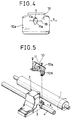
- a conventional impact serial printer will be described with reference to Figs. 5 to 9.
- a cylindrical platen 1 is driven for rotation by a platen driving unit, not shown.
- a carriage guide shaft 4 is extended with its axis in parallel to that of the platen 1, and a carriage 3 mounted with a print head 2 is supported on the carriage guide shaft 4 for sliding movement along the carriage guide shaft 4.
- the carriage 3 is driven for back-and-forth movement by a carriage driving unit, not shown.
- the print head 2 is of a dot matrix print type provided on its front end with a plurality of wires 2a having front ends arranged in a single column.
- a wire driving unit moves the wires 2a back and forth.
- the print head 2 is disposed with the front ends of the wires 2a opposite the platen 1 with a small gap therebetween.
- the print head 2 may be provided with a plurality of wires having front ends arranged in two or more columns instead of a single column.
- a ribbon mask 10 is attached to the carriage 3 so as to be positioned between the platen 1 and the print head 2.
- the ribbon mask 10 consists of a frame 10a screwed to the carriage 3, and a very thin, filmy masking plate 10b attached to the frame 10a.
- the masking plate 10b is provided with an aperture 11 through which the front ends of the wires 2a provided on the front end of the print head 2 are allowed to project.
- the shape of the aperture 11 is a rhombus (Fig. 7), an ellipse (Fig. 8) or a hexagon (Fig. 9).
- the aperture 11 of either shape is symmetric with respect to a platen center C , which is a normal to the platen 1 at a position on the platen nearest to the front end of the print head 2.
- a portion of the ribbon mask 10 corresponding to the platen center C is nearest to the platen 1 as well as the front end of the print head 2.
- the platen center C in Figs. 7, 8 and 9 is a path along which a point on the print head 2 corresponding to the platen center C moves as the print head 2 moves.
- a ribbon feed mechanism is mounted on the carriage 3 to feed an ink ribbon 5 through a space between the platen 1 and the print head 2. As shown in Fig. 6, the ink ribbon 5 extends behind the ribbon mask 10 on the side of the print head 2.
- a recording sheet P is fed between the platen 1 and the ribbon mask 10, and then the wires 2a of the print head 2 are driven selectively to impact the platen 1 with the front ends of the wires 2a; consequently, portions of the ink ribbon 5 corresponding to the wires 2a impacting on the platen 1 are transferred to the recording sheet P to print dots.
- the carriage 3 is driven by the carriage driving unit to print a line of characters by moving the print head 2 along the axis of the platen 1 in a direction indicated by double-head arrow X in Fig. 5.
- Such a printing operation is repeated every time the platen 1 is turned through an angle corresponding to the line spacing to print all the lines of characters on the recording sheet P .
- the recording sheet P Since the recording sheet P is shielded with the ribbon mask 10 from the ink ribbon 5, the recording sheet P can surely be prevented from being smeared with the ink of the ink ribbon 5 as the print head 2 is moved back and forth along the platen 1.
- the present invention provides a printer comprising:-
- the overall shape of the aperture remains balanced with an equal area appearing on each side of a central line but with the shape having an effective tilt so that jamming does not occur.
- the platen centre is a normal to the platen at a position nearest to the front end of the print head. Characters are printed on a recording sheet wound round the platen while the print head is moved back and forth and the platen is turned for feeding the recording sheet. Since the recording sheet is shielded from the ink ribbon by the ribbon mask, the recording sheet is not smeared accidentally by the ink. Since the floating edges the recording sheet are able to slide along the inclined edges of the aperture even if the floating edges of the recording sheet are caught by the edges of the aperture, the recording sheet is not caught by the aperture and hence jamming and breakage of the ribbon mask can be prevented.
- a printer in a preferred embodiment according to the present invention will be described with reference to Fig. 1, in which parts like or corresponding to those previously described with reference to Figs. 5 to 9 are denoted by the same reference characters and the description thereof will be omitted.
- a ribbon mask 10 has a masking plate 10a provided with a parallelogrammatic aperture 11 having opposite edges 11a inclined to a direction perpendicular to the direction of movement of the print head 2 indicated by a double-head arrow X in Fig. 1 and formed so as to extend across a platen center C , namely, a normal to the platen 1 at a position nearest to the front end of the print head 2.
- a point on the print head 2 coinciding with the platen center C moves along the platen center C as the print head 2 moves.
- Platen centers C shown in Figs. 2 to 4 are of the same definition.
- the aperture 11 has a polygonal shape, the least necessary area of the front end of the print head 2 is exposed to the platen 1 to shield the recording sheet P effectively from the ink ribbon 5, the inclined edges 11a inclining at a large angle to the platen center C ensures the escape of the recording sheet P from the platen center C .
- the aperture 11 is designed in a shape effective for preventing the recording sheet P being caught by the aperture 11, the ribbon mask (hence the printer) is simple in construction and small in size.
- the shape of the aperture 11 of the ribbon mask 10 need not necessarily be a parallelogram; the aperture 11 may be of any shape provided that the aperture 11 has inclined edges 11a intersecting the platen center C .
- the ribbon mask 10 may employ a masking plate 10a provided with an aperture 11 having the shape of a rhombus and formed with its horizontal axis of symmetry vertically dislocated from the platen center C or inclined at a predetermined angle to the platen center C as shown in Fig. 2 so that the inclined edges 11a thereof intersect the platen center C obliquely.
- the ribbon mask 10 may employ a masking plate 10a provided with an aperture 11 having the shape of an ellipse formed with its axis of symmetry dislocated vertically from the platen center C or inclined at a predetermined angle to the platen center C as shown in Fig. 3 so that a portions 11a of the elliptic aperture 11 intersect the platen center C obliquely. Since the edge of the aperture 11 is a smooth curve, the recording sheet P being caught by the aperture 11 can be prevented even if the angle of inclination of the inclined portions 11a is small.
- the ribbon mask 10 may employ a masking plate 10a provided with an aperture 11 having the shape of a hexagon formed with its axis of symmetry dislocated vertically from the platen center C or inclined at a predetermined angle to the platen center C as shown in Fig. 4 so that inclined edges 11a thereof intersect the platen center C obliquely.
Landscapes
- Handling Of Sheets (AREA)
Claims (3)
- Une imprimante comprenant :un rouleau (1) autour duquel est enroulée une feuille d'enregistrement ;une tête d'impression (2) disposée avec son extrémité antérieure en face du rouleau et portée en vue de glisser le long d'un axe d'avance (X) du rouleau ; etun masque de ruban (10) monté fixe sur la tête d'impression, et présentant une plaque de masquage (10a) maintenue entre le rouleau et un ruban à encre (5) s'étendant à travers un espace entre le rouleau et la tête d'impression, ayant un axe principal (C) qui est parallèle à l'axe d'avance (X) du rouleau et présentant une ouverture (11) pour n'exposer au rouleau que l'extrémité antérieure de la tête d'impression ;l'ouverture (11) étant d'une forme sensiblement équilibrée de manière à être symétrique ou conforme autour d'un axe (19) de symétrie ou de conformité et présentant des bords opposés (11a) inclinés chacun dans une direction perpendiculaire à la direction de déplacement de la tête d'impression ; caractérisée en ce que l'axe (19) de symétrie ou de conformité de l'ouverture coupe l'axe principal (C) de la plaque de masquage selon un angle faible.
- Une imprimante selon la revendication 1, dans laquelle l'ouverture (11) de la plaque de masquage a la forme d'un polygone.
- Une imprimante selon la revendication 1, dans laquelle l'ouverture (11) de la plaque de masquage a la forme d'une ellipse.
Applications Claiming Priority (2)
| Application Number | Priority Date | Filing Date | Title |
|---|---|---|---|
| JP51077/90 | 1990-05-16 | ||
| JP5107790 | 1990-05-16 |
Publications (2)
| Publication Number | Publication Date |
|---|---|
| EP0457560A1 EP0457560A1 (fr) | 1991-11-21 |
| EP0457560B1 true EP0457560B1 (fr) | 1996-09-18 |
Family
ID=12876751
Family Applications (1)
| Application Number | Title | Priority Date | Filing Date |
|---|---|---|---|
| EP91304346A Expired - Lifetime EP0457560B1 (fr) | 1990-05-16 | 1991-05-15 | Imprimante |
Country Status (4)
| Country | Link |
|---|---|
| US (1) | US5154521A (fr) |
| EP (1) | EP0457560B1 (fr) |
| KR (1) | KR950013587B1 (fr) |
| DE (1) | DE69122166T2 (fr) |
Families Citing this family (3)
| Publication number | Priority date | Publication date | Assignee | Title |
|---|---|---|---|---|
| US5694526A (en) * | 1996-04-10 | 1997-12-02 | Micro General Corporation | Postage meter having a dot matrix printer |
| JP2001205833A (ja) * | 2000-01-27 | 2001-07-31 | Seiko Precision Inc | ドットプリンタ |
| WO2003103366A2 (fr) * | 2002-06-05 | 2003-12-18 | Invacare Corporation | Scooter a roues centrales |
Family Cites Families (14)
| Publication number | Priority date | Publication date | Assignee | Title |
|---|---|---|---|---|
| JPS5916938B2 (ja) * | 1979-09-28 | 1984-04-18 | 沖電気工業株式会社 | シリアルプリンタ |
| JPS5829447U (ja) * | 1981-08-21 | 1983-02-25 | セイコーエプソン株式会社 | 印字装置 |
| JPS6029643A (ja) * | 1983-07-28 | 1985-02-15 | Hitachi Electronics Eng Co Ltd | 微粒子検出器 |
| JPS6110479A (ja) * | 1984-06-25 | 1986-01-17 | Canon Inc | インクリボンカセツト |
| DE3502470C1 (de) * | 1985-01-25 | 1986-07-24 | Mannesmann AG, 4000 Düsseldorf | Einrichtung für Matrixdrucker, insbes. für serielle Matrixdrucker |
| JPS6223771A (ja) * | 1985-07-24 | 1987-01-31 | Nec Corp | 傾斜翼を持つリボンマスクシ−ト |
| US4712935A (en) * | 1985-11-04 | 1987-12-15 | The Standard Register Company | Blank document guard in a check writing machine |
| JPS62151365A (ja) * | 1985-12-25 | 1987-07-06 | Tamura Electric Works Ltd | 印字機構のマスク構造 |
| JPS63145068A (ja) * | 1986-12-10 | 1988-06-17 | Oki Electric Ind Co Ltd | プラテンギヤツプ調整装置 |
| DE3786759T2 (de) * | 1986-12-10 | 1994-03-03 | Oki Electric Ind Co Ltd | Farbbandschutz für Drucker. |
| US4856923A (en) * | 1987-05-18 | 1989-08-15 | Dataproducts Corporation | Ribbon shield |
| GB2209501B (en) * | 1987-09-05 | 1991-10-02 | Unisys Corp | Document printing apparatus |
| JPH074925Y2 (ja) * | 1988-02-13 | 1995-02-08 | シチズン時計株式会社 | プリンタのリボンマスク |
| US4964556A (en) * | 1989-09-14 | 1990-10-23 | Precision Handling Devices, Inc. | Forms feed tractor with lid which facilitates forms alignment |
-
1991
- 1991-05-15 US US07/700,258 patent/US5154521A/en not_active Expired - Fee Related
- 1991-05-15 KR KR1019910007863A patent/KR950013587B1/ko not_active Expired - Fee Related
- 1991-05-15 DE DE69122166T patent/DE69122166T2/de not_active Expired - Fee Related
- 1991-05-15 EP EP91304346A patent/EP0457560B1/fr not_active Expired - Lifetime
Also Published As
| Publication number | Publication date |
|---|---|
| US5154521A (en) | 1992-10-13 |
| DE69122166D1 (de) | 1996-10-24 |
| KR910019789A (ko) | 1991-12-19 |
| KR950013587B1 (ko) | 1995-11-13 |
| DE69122166T2 (de) | 1997-04-03 |
| EP0457560A1 (fr) | 1991-11-21 |
Similar Documents
| Publication | Publication Date | Title |
|---|---|---|
| US4165188A (en) | Ribbon mask and guide for dot matrix impact printers | |
| EP0837423B1 (fr) | Système d'impression | |
| EP0073114A2 (fr) | Masque pour ruban encreur dans une imprimante par points à aiguilles | |
| CA1217972A (fr) | Imprimante par frappe | |
| US3964595A (en) | Ribbon guide for a serial printer | |
| US5154521A (en) | Printer having ribbon mask for reducing interference with recording sheet | |
| US6367910B1 (en) | Multiple inline print head with servo driven mechanical interlocked print head assemblies | |
| US4423971A (en) | Printer with a document guide device | |
| EP0837425A2 (fr) | Imprimantes à jet d'encre | |
| JPS60165276A (ja) | 印字装置の用紙案内機構 | |
| DE69217525T2 (de) | Papierführungsvorrichtung für Seriendrucker | |
| EP0837421A2 (fr) | Impression à jet d'encre | |
| WO1992018948A1 (fr) | Imprimante matricielle | |
| JP2530855Y2 (ja) | リボンマスク | |
| US5180238A (en) | Dot impact printer | |
| US4363268A (en) | Drum type bar code line printer | |
| JP2811326B2 (ja) | リボンセパレータ | |
| JP3348253B2 (ja) | 媒体ガイド機構 | |
| US5083876A (en) | Print wire alignment in a wire dot printer | |
| JP3083971B2 (ja) | インクリボンカセット | |
| EP0775586A1 (fr) | Limiter la largeur du chariot d'impression à jet d'encre | |
| JPH0262274A (ja) | 通帳プリンタの印字部の構造 | |
| US6527463B2 (en) | Printer and print medium drive system | |
| EP0267720A2 (fr) | Guidage flexible du fil d'impression pour imprimante à matrice de points | |
| JPH0469070B2 (fr) |
Legal Events
| Date | Code | Title | Description |
|---|---|---|---|
| PUAI | Public reference made under article 153(3) epc to a published international application that has entered the european phase |
Free format text: ORIGINAL CODE: 0009012 |
|
| 17P | Request for examination filed |
Effective date: 19910523 |
|
| AK | Designated contracting states |
Kind code of ref document: A1 Designated state(s): DE FR GB IT |
|
| 17Q | First examination report despatched |
Effective date: 19930721 |
|
| RAP1 | Party data changed (applicant data changed or rights of an application transferred) |
Owner name: KABUSHIKI KAISHA TEC |
|
| GRAA | (expected) grant |
Free format text: ORIGINAL CODE: 0009210 |
|
| AK | Designated contracting states |
Kind code of ref document: B1 Designated state(s): DE FR GB IT |
|
| REF | Corresponds to: |
Ref document number: 69122166 Country of ref document: DE Date of ref document: 19961024 |
|
| ET | Fr: translation filed | ||
| ITF | It: translation for a ep patent filed | ||
| PLBE | No opposition filed within time limit |
Free format text: ORIGINAL CODE: 0009261 |
|
| STAA | Information on the status of an ep patent application or granted ep patent |
Free format text: STATUS: NO OPPOSITION FILED WITHIN TIME LIMIT |
|
| 26N | No opposition filed | ||
| PGFP | Annual fee paid to national office [announced via postgrant information from national office to epo] |
Ref country code: DE Payment date: 20010508 Year of fee payment: 11 |
|
| PGFP | Annual fee paid to national office [announced via postgrant information from national office to epo] |
Ref country code: GB Payment date: 20010509 Year of fee payment: 11 |
|
| PGFP | Annual fee paid to national office [announced via postgrant information from national office to epo] |
Ref country code: FR Payment date: 20010518 Year of fee payment: 11 |
|
| REG | Reference to a national code |
Ref country code: GB Ref legal event code: IF02 |
|
| PG25 | Lapsed in a contracting state [announced via postgrant information from national office to epo] |
Ref country code: GB Free format text: LAPSE BECAUSE OF NON-PAYMENT OF DUE FEES Effective date: 20020515 |
|
| PG25 | Lapsed in a contracting state [announced via postgrant information from national office to epo] |
Ref country code: DE Free format text: LAPSE BECAUSE OF NON-PAYMENT OF DUE FEES Effective date: 20021203 |
|
| GBPC | Gb: european patent ceased through non-payment of renewal fee |
Effective date: 20020515 |
|
| PG25 | Lapsed in a contracting state [announced via postgrant information from national office to epo] |
Ref country code: FR Free format text: LAPSE BECAUSE OF NON-PAYMENT OF DUE FEES Effective date: 20030131 |
|
| REG | Reference to a national code |
Ref country code: FR Ref legal event code: ST |
|
| PG25 | Lapsed in a contracting state [announced via postgrant information from national office to epo] |
Ref country code: IT Free format text: LAPSE BECAUSE OF NON-PAYMENT OF DUE FEES;WARNING: LAPSES OF ITALIAN PATENTS WITH EFFECTIVE DATE BEFORE 2007 MAY HAVE OCCURRED AT ANY TIME BEFORE 2007. THE CORRECT EFFECTIVE DATE MAY BE DIFFERENT FROM THE ONE RECORDED. Effective date: 20050515 |
|
| PGFP | Annual fee paid to national office [announced via postgrant information from national office to epo] |
Ref country code: IT Payment date: 20070730 Year of fee payment: 17 |
|
| PGRI | Patent reinstated in contracting state [announced from national office to epo] |
Ref country code: IT Effective date: 20091201 |
|
| PGRI | Patent reinstated in contracting state [announced from national office to epo] |
Ref country code: IT Effective date: 20091201 |