EP0457889B1 - Verfahren und vorrichtung zur behandlung von verunreinigtem erdreich - Google Patents
Verfahren und vorrichtung zur behandlung von verunreinigtem erdreich Download PDFInfo
- Publication number
- EP0457889B1 EP0457889B1 EP91901212A EP91901212A EP0457889B1 EP 0457889 B1 EP0457889 B1 EP 0457889B1 EP 91901212 A EP91901212 A EP 91901212A EP 91901212 A EP91901212 A EP 91901212A EP 0457889 B1 EP0457889 B1 EP 0457889B1
- Authority
- EP
- European Patent Office
- Prior art keywords
- kiln
- soil
- exhaust gases
- exhaust stream
- temperature
- Prior art date
- Legal status (The legal status is an assumption and is not a legal conclusion. Google has not performed a legal analysis and makes no representation as to the accuracy of the status listed.)
- Expired - Lifetime
Links
- 239000002689 soil Substances 0.000 title claims abstract description 51
- 238000000034 method Methods 0.000 title claims description 27
- 229930195733 hydrocarbon Natural products 0.000 claims abstract description 35
- 150000002430 hydrocarbons Chemical class 0.000 claims abstract description 35
- 230000003197 catalytic effect Effects 0.000 claims abstract description 23
- 238000001914 filtration Methods 0.000 claims abstract description 18
- 239000004215 Carbon black (E152) Substances 0.000 claims abstract description 15
- 239000000356 contaminant Substances 0.000 claims abstract description 15
- 239000000470 constituent Substances 0.000 claims abstract description 9
- 238000011068 loading method Methods 0.000 claims abstract description 7
- 230000001105 regulatory effect Effects 0.000 claims abstract description 7
- 230000003134 recirculating effect Effects 0.000 claims abstract 4
- 239000007789 gas Substances 0.000 claims description 60
- 238000002485 combustion reaction Methods 0.000 claims description 45
- 239000002699 waste material Substances 0.000 claims description 20
- ATUOYWHBWRKTHZ-UHFFFAOYSA-N Propane Chemical compound CCC ATUOYWHBWRKTHZ-UHFFFAOYSA-N 0.000 claims description 16
- 239000007787 solid Substances 0.000 claims description 11
- 239000000567 combustion gas Substances 0.000 claims description 8
- 239000001294 propane Substances 0.000 claims description 8
- 230000001939 inductive effect Effects 0.000 claims description 6
- 238000012544 monitoring process Methods 0.000 claims description 4
- 230000005484 gravity Effects 0.000 claims description 2
- 230000033001 locomotion Effects 0.000 claims description 2
- 239000003208 petroleum Substances 0.000 claims description 2
- 230000001276 controlling effect Effects 0.000 claims 3
- 239000000463 material Substances 0.000 description 9
- 239000003054 catalyst Substances 0.000 description 6
- 239000000446 fuel Substances 0.000 description 6
- 230000001965 increasing effect Effects 0.000 description 3
- 238000010791 quenching Methods 0.000 description 3
- 239000006200 vaporizer Substances 0.000 description 3
- 238000004140 cleaning Methods 0.000 description 2
- 239000013256 coordination polymer Substances 0.000 description 2
- 230000006378 damage Effects 0.000 description 2
- 238000004880 explosion Methods 0.000 description 2
- 239000000203 mixture Substances 0.000 description 2
- 238000009834 vaporization Methods 0.000 description 2
- 230000008016 vaporization Effects 0.000 description 2
- 238000003915 air pollution Methods 0.000 description 1
- QVGXLLKOCUKJST-UHFFFAOYSA-N atomic oxygen Chemical compound [O] QVGXLLKOCUKJST-UHFFFAOYSA-N 0.000 description 1
- 238000009835 boiling Methods 0.000 description 1
- 238000006243 chemical reaction Methods 0.000 description 1
- 238000010276 construction Methods 0.000 description 1
- 230000002596 correlated effect Effects 0.000 description 1
- 239000002283 diesel fuel Substances 0.000 description 1
- 238000007599 discharging Methods 0.000 description 1
- 230000000694 effects Effects 0.000 description 1
- 230000007613 environmental effect Effects 0.000 description 1
- 238000003912 environmental pollution Methods 0.000 description 1
- 239000004744 fabric Substances 0.000 description 1
- 230000010006 flight Effects 0.000 description 1
- 239000003502 gasoline Substances 0.000 description 1
- 231100001261 hazardous Toxicity 0.000 description 1
- 238000010438 heat treatment Methods 0.000 description 1
- 239000012535 impurity Substances 0.000 description 1
- 238000007689 inspection Methods 0.000 description 1
- 238000005259 measurement Methods 0.000 description 1
- 238000012986 modification Methods 0.000 description 1
- 230000004048 modification Effects 0.000 description 1
- 239000001301 oxygen Substances 0.000 description 1
- 229910052760 oxygen Inorganic materials 0.000 description 1
- 230000008447 perception Effects 0.000 description 1
- 238000011084 recovery Methods 0.000 description 1
- 238000007669 thermal treatment Methods 0.000 description 1
- 238000011144 upstream manufacturing Methods 0.000 description 1
- 238000013022 venting Methods 0.000 description 1
- 238000003911 water pollution Methods 0.000 description 1
Images

Classifications
-
- F—MECHANICAL ENGINEERING; LIGHTING; HEATING; WEAPONS; BLASTING
- F23—COMBUSTION APPARATUS; COMBUSTION PROCESSES
- F23G—CREMATION FURNACES; CONSUMING WASTE PRODUCTS BY COMBUSTION
- F23G7/00—Incinerators or other apparatus for consuming industrial waste, e.g. chemicals
- F23G7/06—Incinerators or other apparatus for consuming industrial waste, e.g. chemicals of waste gases or noxious gases, e.g. exhaust gases
- F23G7/07—Incinerators or other apparatus for consuming industrial waste, e.g. chemicals of waste gases or noxious gases, e.g. exhaust gases in which combustion takes place in the presence of catalytic material
-
- B—PERFORMING OPERATIONS; TRANSPORTING
- B09—DISPOSAL OF SOLID WASTE; RECLAMATION OF CONTAMINATED SOIL
- B09C—RECLAMATION OF CONTAMINATED SOIL
- B09C1/00—Reclamation of contaminated soil
- B09C1/06—Reclamation of contaminated soil thermally
-
- F—MECHANICAL ENGINEERING; LIGHTING; HEATING; WEAPONS; BLASTING
- F23—COMBUSTION APPARATUS; COMBUSTION PROCESSES
- F23G—CREMATION FURNACES; CONSUMING WASTE PRODUCTS BY COMBUSTION
- F23G5/00—Incineration of waste; Incinerator constructions; Details, accessories or control therefor
- F23G5/006—General arrangement of incineration plant, e.g. flow sheets
-
- F—MECHANICAL ENGINEERING; LIGHTING; HEATING; WEAPONS; BLASTING
- F23—COMBUSTION APPARATUS; COMBUSTION PROCESSES
- F23G—CREMATION FURNACES; CONSUMING WASTE PRODUCTS BY COMBUSTION
- F23G5/00—Incineration of waste; Incinerator constructions; Details, accessories or control therefor
- F23G5/02—Incineration of waste; Incinerator constructions; Details, accessories or control therefor with pretreatment
- F23G5/027—Incineration of waste; Incinerator constructions; Details, accessories or control therefor with pretreatment pyrolising or gasifying stage
- F23G5/0276—Incineration of waste; Incinerator constructions; Details, accessories or control therefor with pretreatment pyrolising or gasifying stage using direct heating
-
- F—MECHANICAL ENGINEERING; LIGHTING; HEATING; WEAPONS; BLASTING
- F23—COMBUSTION APPARATUS; COMBUSTION PROCESSES
- F23G—CREMATION FURNACES; CONSUMING WASTE PRODUCTS BY COMBUSTION
- F23G5/00—Incineration of waste; Incinerator constructions; Details, accessories or control therefor
- F23G5/40—Portable or mobile incinerators
-
- F—MECHANICAL ENGINEERING; LIGHTING; HEATING; WEAPONS; BLASTING
- F23—COMBUSTION APPARATUS; COMBUSTION PROCESSES
- F23G—CREMATION FURNACES; CONSUMING WASTE PRODUCTS BY COMBUSTION
- F23G7/00—Incinerators or other apparatus for consuming industrial waste, e.g. chemicals
- F23G7/14—Incinerators or other apparatus for consuming industrial waste, e.g. chemicals of contaminated soil, e.g. by oil
-
- F—MECHANICAL ENGINEERING; LIGHTING; HEATING; WEAPONS; BLASTING
- F23—COMBUSTION APPARATUS; COMBUSTION PROCESSES
- F23G—CREMATION FURNACES; CONSUMING WASTE PRODUCTS BY COMBUSTION
- F23G2201/00—Pretreatment
- F23G2201/50—Devolatilising; from soil, objects
Definitions
- This invention relates to treatment of contaminated soil; and more particularly relates to a novel and improved method and apparatus for the removal of volatile organic contaminating materials from the soil.
- a method and apparatus are known from US-A- 4 827 854.
- a novel and improved vehicle-mounted apparatus for removal of hydrocarbon contaminants from soil or other waste matter which comprises a unitary wheeled frame, an inclined rotary kiln mounted on the frame including an inlet at an upper end of the kiln and a discharge end at a lower end of the kiln, and means for rotating the kiln about its longitudinal axis, a burner assembly mounted in the discharge end of the kiln including ignitor means for directing a gaseous flame into the interior of the kiln toward the inlet end, means on the frame for loading waste matter into the inlet end of the kiln for advancement along the kiln under rotation thereof whereby to be directly heated by the gaseous flame for a time period sufficient to volatilize any hydrocarbon constituents in the waste matter, blower means on the frame for inducing the flow of an exhaust stream consisting of any combustion gases and volatilized hydrocarbons and fines upwardly through the kiln including
- first temperature monitoring means are associated with the catalytic incinerator means for sensing the temperature of the exhaust stream prior to its passage into the catalytic incinerator means
- second temperature monitoring means are associated with the catalytic incinerator means for sensing the temperature of the exhaust stream at a discharge end of the catalytic incinerator means.
- the method for removing contaminants from soil or other waste matter comprises the steps of advancing the soil through a dryer having a combustion chamber therein, exposing the soil to a gaseous flame in the combustion chamber to volitalize certain of the contaminants in the soil, inducing the flow of the volatilized contaminants in the form of exhaust gases from the combustion chamber whereby to create a negative pressure in the combustion chamber, and drawing outside air into the exhaust gases, filtering solids from the exhaust gases as they are discharged from the dryer and transferring the solids into a waste material collection area, preheating the exhaust gases to raise their temperature after filtering the solids therefrom, followed by incinerating the exhaust gases at a higher temperature level than the dryer and less than 927°C (1700°F) to burn any unburned contaminants remaining in the exhaust gases.
- the preferred apparatus of the present invention comprises a dryer or kiln 10 mounted for rotation about an inclined axis for gravity flow of contaminated soil from a loader 11 at upper inlet end 12 downwardly through a combustion area 13 adjacent to lower discharge end 14.
- the soil or remaining aggregates or waste matter are discharged from the lower end 14 through line 15 into a waste collection area 16.
- a slide gate 17 is stationed at the inlet end 12 to regulate the admission of fresh air from the atmosphere into the exhaust stream from the combustion area 13.
- the downward flow of soil through the kiln 10 is regulated in part by flights located internally of the kiln and which in a conventional manner are capable of exposing it as much as possible to the combustion gases.
- a burner system 18 extends through the lower end 14 of the kiln 10 and which includes a combustion air blower 20 to direct air into the burner system 18 to mix with a propane fuel and discharge as a vapor through a burner nozzle into the combustion area 13.
- the soil temperature in the combustion area is maintained in the range of 177°C (350°F) to 343°C (650°F) for most complete burning or volatilization of the lighter fraction hydrocarbons in the soil.
- the combustion gases formed in the combustion area 13 intermix with the volatilized hydrocarbons and are drawn off as an exhaust stream in countercurrent relation to the movement of the soil upwardly through the kiln 10 and escape from the inlet end 12 under the influence of the suction side of a process air blower 22.
- These exhaust gases are delivered via conduit 23 and baghouse 24 into the suction side of the blower 22.
- baghouse 24 any fines are removed from the gases and collected in the lower end of the baghouse where they are advanced by an auger 26 toward one end of the baghouse for removal through line 28 to the waste collection area 16.
- the main process air blower 22 draws the exhaust gases from the baghouse 24 through line 27 and discharges through line 30 which leads to a preheat burner 31 at the inlet end of a catalytic incinerator 32.
- a preheat burner 31 at the inlet end of a catalytic incinerator 32.
- the exhaust gases recovered from the inlet end of the kiln will have dropped in temperature after removal from the combustion area 13 into the range of 107°C (225°F) to 191°C (375°F). It is therefore necessary to raise the temperature of these gases through the preheat burner 31 to no less than 316°C (600°F), this temperature being monitored between the preheat burner and catalyst bed.
- a variable control damper 34 is positioned in the line 30 to modulate the mass flow rate of gases through the line 30, particularly during start-up.
- An on/off damper 35 is positioned in the line 30 directly upstream of the inlet to the incinerator 32; and, since the incinerator is not energized until the gases are brought up to temperature during the start-up period, similarly the on/off damper 35 will remain in an off position in the initial stages of start-up but another damper 36 is open to permit venting of any exhaust gases to the atmosphere.
- a quench air blower 33 communicates with the line 30 to supply additional air, it needed, to be intermixed with the exhaust gases flowing into the catalytic incinerator.
- Another variable damper 40 is positioned in line 30′ to regulate the amount of exhaust gases recirculated back to the combustion area 13.
- a main control panel CP will sense the temperatures in the conduit 23 as well as the flow line 15 and has a connecting line 38 to an auxiliary control panel CP1 for the incinerator 32.
- the control panels are correlated to modulate the fuel/air ratio and particularly the flow rate of air into the combustion area to optimize the volatilization of the hydrocarbons from the soil but at the same time assure that the concentration of hydrocarbons in the exhaust gases will not exceed a predetermined value or limit. In this way, it is possible to circulate the gases through baghouse 24 to filter out any solids or fines as a preliminary to further incineration of any unburned hydrocarbons.
- the exhaust gases are clear and colorless, there may nevertheless be varying amounts of unburned or partially burned hydrocarbons contained in the gases which cannot be emitted directly into the atmosphere. Accordingly, it is desirable in accordance with the present invention to employ a form of incinerator which will completely eradicate the unburned or partially burned constituents in the gases and most desirably at the lowest possible temperature. To this end, the catalytic incinerator 32 will effectively treat gases which have been heated to not less than 316°C (600°F) and to raise them to a temperature of no more than 649°C (1200°F).
- a preferred form of catalytic incinerator is the Model CKM-300 CATOX Reactor, in which gases are directed into the incinerator and advanced through a catalyst bed which will cause impurities in the gases to completely oxidize substantially before being vented to the atmosphere. Automatic temperature limit switches at the inlet and discharge ends insure the complete destruction of the hydrocarbons in the presence of oxygen.
- An alternate method of incineration is to employ a thermal incinerator, such as, a Model Flame Bath 3.6-D-5. Typically, the thermal incinerator will perform the same chemical reaction as the catalytic incinerator but at a much higher temperature in the range of 704°C (1300°F) to 927°C (1700°F).
- the catalytic incinerator is preferred since it utilizes considerably less fuel to accomplish the desired end result, is less expensive to operate and produces less of the gases which may tend to produce a "greenhouse” effect. Furthermore, the catalytic incinerator lends itself well to use as a part of a compact, truck-mounted unit as hereinafter described which is readily transportable to different intended sites of use.
- Thermocouples T1 and T2 are provided at the inlet and discharge ends, respectively, of the incinerator 32 to monitor the inlet and exhaust temperatures of the gases.
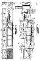
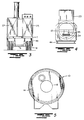
- FIG. 1 to 5 a preferred apparatus 42 for treating contaminated soil in which the entire apparatus is mounted on a unitary wheeled frame or trailer bed as designated at T and which has ground-engaging wheels W at the rear end of the trailer journaled on a common shaft S and suspended from the frame T in a conventional manner.
- a forward end of the truck bed T has a standard hitch H and, although not shown, suitable legs are mounted at the corners in order to support the bed T in a level position when the apparatus 42 is in operation.
- the loader 11, dryer 10 and incinerator 32 are arranged in tandem along one side of the bed T, and the baghouse 24 extends along the opposite side in closely spaced, parallel relation to the dryer 10.
- the dryer 10 is mounted on an inclined base 44 within a generally rectangular open frame 46 which is permanently affixed within a recessed portion on one side of the main frame T so that the dryer 10 is suspended partially beneath the main frame T, and the frame is reinforced by angular braces 47 and 48 extending from the upper end of the frame 46 downwardly in a forward and rearward direction, respectively, to rest on the upper surface of the main frame T.
- the dryer is inclined such that the inlet end 12 is slightly above the level of the frame T, and the outlet end 14 is below the level of the inlet end 12 with its center line substantially aligned with the main frame T.
- the dryer 10 is journaled for rotation on the base 44 by forward and rearward spaced circumferential bearings 49, and a chain sprocket 50 extends circumferentially of the dryer for rotation by a motor, not shown, but which is drivingly connected to the chain sprocket 50.
- the loader 11 is mounted at the front corner of the truck bed and includes a hopper or bin 52 having an upper inclined grate 53 at the upper end of the hopper 52 to limit the size of materials that can be deposited through the hopper onto a horizontal conveyor 54.
- the grate 53 is inclined downwardly toward one side of the bed T on the dryer side so that any materials that will not pass through the grate 53 can accumulate on the ground surface to one side of the bed T.
- the conveyor 54 is motor-driven to advance the materials in a rearward direction through the entrance 55 at the forward inlet end 12, as best seen from Figure 4.
- the soil then is advanced by the rotating dryer 10 downwardly toward the combustion area 13 preferably with the aid of spiral flighting, not shown, along the internal surface of.the dryer.
- the flighting is well known and intended to cause tumbling and some further reduction in size of the soil materials as they advance into the combustion area 13.
- the flighting is modified somewhat so as to retard the advancement of the soil and assure complete exposure to the flame generated by the main process burner 18 for maximum burning of the hydrocarbons in the soil.
- generally paddle-shaped flighting may be mounted along the internal wall of the dryer in the combustion area 13 and which will tend more to pick up the soil and to retain it in shallow dish-shaped pockets as a preliminary to discharge via elevator E into the waste collection area 16.
- the main process burner 18 is designed to thoroughly burn the lighter fractions of the hydrocarbons in the soil and, for this purpose, should be capable of heating the soil to a temperature range on the order of 177°C (350°F) to 343°C (650°F).
- One type of burner which can be employed is a propane burner Model CR4-9-30, and which will cause vaporization and mixture of a propane fuel with combustion air supplied by the combustion air blower incorporated into the burner 18.
- the burner proper is aligned with the central opening in the outlet end 14 for projection into the combustion area 13 and is normally capable of raising the temperature of the flame within an enclosed space, such as, the combustion area 13 into the range of 1816°C (3300°F).
- a portion of the exhaust gases from the discharge side of the baghouse may be diverted over line 30′ into the combustion area 13 for mixture with the exhaust stream to maintain the hydrocarbon concentration below a predetermined level.
- Temperature control is further aided by the introduction of fresh air from the atmosphere through a slide gate 17 which, as shown in Figure 5, is mounted in the exhaust duct 23 at the inlet end 12.
- the slide gate 17 can be adjustably controlled to regulate the amount of air drawn into the exhaust stream 13 in relation to the negative pressure condition created by the process blower 22.
- the process blower 22 is mounted on the frame 46 toward the rearward end, and the conduit 30 together with associated dampers extend rearwardly and downwardly into the preheat burner 31 which is mounted on the truck bed directly in front of the catalytic incinerator 32. Housings for the control panels CP and CP1 are mounted at the rear end of the bed T so as to be easily accessible to the operator.
- the quench air blower 33 Also shown mounted on the frame 46 above the dryer 10 are the quench air blower 33 and a combustion air blower 60 for the preheat burner 31.
- the combustion air blower 60 is not illustrated in the plan view of Figure 2; nor its connection into the preheat burner 31.
- combustion gases along with any volatilized fractions created in the combustion area 13 are drawn in an upward, forward direction through the interior of the dryer 10 and conveyed through the duct 23 at the inlet end 12 of the dryer into the inlet end of the baghouse 24 which is stationed alongside of the dryer 10 on the frame T.
- the duct 23 extends transversely of the length of the dryer 10 and baghouse 24 so that the exhaust gases flow over a very short distance preliminary to passing through the baghouse 24.
- filter 24 is a pulse jet baghouse having a capacity of 1.416m3s ⁇ 1 (3000 scfm). When the exhaust gases exit from the dryer 10, they will have cooled off slightly from the combustion area 13 so as to be in a range more on the order of 107°C (225°F) to 191°C (375°F). It is of a type having upper lift or inspection doors 63 and 64 and an auger as represented at 26 passing through the base of the baghouse to collect the fines from the filter bags and advance them through line 28 into the waste collection area 16 as previously described.
- the exhaust gases are drawn from the dryer 10, through the baghouse 24 and through discharge line 27 into the intake side of the blower 22.
- An air compressor 65 and propane vaporizer 66 are mounted on the truck bed directly in front of the baghouse, and a generator 68 is mounted on the truck bed to the rear of the baghouse, the generator being designed to operate all electrical equipment and controls.
- the generator 68 is started and warmed up.
- the propane vaporizer 66 for the preheat burner 31 and the burner 18 are started up and the outlet pressure in the combustion area 13 is checked.
- this pressure should be a minimum of 827 kPa (120 psi).
- the catalyst incinerator 32 is then started and, at start-up, the slide gate 17 is opened and the catalyst incinerator inlet from burner 31 is closed.
- the catalyst preheat cycle is started together with the air compressor 65 and the blower 22 with the damper 35 initially in a closed position and a start-up damper is in the open position to vent any gases to the atmosphere.
- the damper 34 is then advanced to an automatic control position so that it will automatically open when the preheat cycle has been completed.
- the burner 18 is started, following which the kiln motor drive and baghouse auger drive are activated.
- the kiln is preheated to 149°C (300°F) by the burner 18 following which the soil to be treated is loaded into the hopper section 11.
- the burner position is increased to maintain a minimum temperature of 135°C (275°F) at the baghouse inlet.
- the burner is regulated to maintain the required discharge temperature and in particular to operate between 177°C (350°F) and 343°C (650°F). Once the material discharge temperature stabilizes for a period of 5 to 10 minutes the material advancement rate may be increased through the kiln.
- the waste material or soil can be advanced through the dryer 10 at the rate of 10.16 to 20.32 Mg (10 to 20 tons) per hour, depending largely on the amount of moisture and pollution contained in the soil. Other factors considered are the atmospheric pressure and type of soil being treated.
- the main process blower 22 is drawing 1.416 m3s ⁇ 1 (3000 cfm) through the baghouse 24 from the combustion area, approximately 0.236 m3s ⁇ 1 (500 cfm) is drawn or recirculated through the line 30′ to be combined with the combustion gases, further assuming that the combustion air blower for the burner 18 is discharging at the rate of 0.708 m3s ⁇ 1 (1500 cfm).
- the balance of the air that is needed to regulate the temperature from the dryer 10 is determined by adjustment of the slide gate 17 at the duct 23 and fresh air is then drawn in through the gate 17 as a result of the negative pressure created by the blower 22 in drawing the gases upwardly through the inlet end of the kiln.
- the concentration of hydrocarbons in the exhaust stream is directly related to the outlet temperature of the incinerator 32.
- This temperature is determined by measurement at the outlet of the catalytic incinerator 32. If the outlet temperature should exceed 621°C (1150°F), the dampers 34 and 35 are regulated to increase the percentage of the gas stream that is returned to the combustion area 13; or the slide gate 17 may be opened further to reduce the fuel/air ratio in the exhaust gas stream and thus the temperature of the gases generated.
- the inlet temperature is monitored between the preheat burner and catalyst bed to assure that the temperature is at 316°C (600°F).
Landscapes
- Engineering & Computer Science (AREA)
- Mechanical Engineering (AREA)
- General Engineering & Computer Science (AREA)
- Environmental & Geological Engineering (AREA)
- Life Sciences & Earth Sciences (AREA)
- Soil Sciences (AREA)
- Chemical & Material Sciences (AREA)
- Chemical Kinetics & Catalysis (AREA)
- Physics & Mathematics (AREA)
- Thermal Sciences (AREA)
- Processing Of Solid Wastes (AREA)
- Excavating Of Shafts Or Tunnels (AREA)
- Gasification And Melting Of Waste (AREA)
Claims (19)
- Verfahren zur Entfernung von Verunreinigungen aus dem Erdreich oder anderem Abfallstoff, bei dem das Erdreich durch einen Trockner (10) mit einem Brennraum (13) darin zur Verflüchtigung bestimmter der Verunreinigungen im Erdreich zur Bildung von Abgasen, die aus dem Trockner (10) abgelassen werden, vorgerückt wird, wobei Außenluft in die Abgase gesaugt wird und jegliche Feststoffe in den Abgasen abfiltriert und in einen Abfallmaterialsammelbereich (16) transportiert werden, dadurch gekennzeichnet, daß das Erdreich im Brennraum (13) einer Gasflamme ausgesetzt wird, um bestimmte der Verunreinigungen im Erdreich zu verflüchtigen, daß die Strömung der erzeugten Abgase aus dem Brennraum (13) bewirkt wird, um dadurch einen Unterdruck im Brennraum (13) zu erzeugen, daß die Abgase zur Erhöhung ihrer Temperatur nach dem Abfiltrieren der Feststoffe daraus vorgewärmt werden, und daß anschließend die Abgase auf einem höheren Temperaturniveau als im Trockner (10) und unter 927°C (1700°F) verbrannt werden, um jegliche nicht verbrannte, in den Abgasen verbliebene Verunreinigungen zu verbrennen.
- Verfahren nach Anspruch 1, das den Schritt der einstellbaren Steuerung der in die Abgase als Reaktion auf die erzeugten Unterdruckzustände eingeführten Außenluftmenge enthält.
- Verfahren nach Anspruch 1, das den Schritt der Rückführung eines Teils der Abgase in den Brennraum (13) nach dem Filtrierungsschritt enthält.
- Verfahren nach Anspruch 1, bei dem die Verunreinigungen leichtere Fraktionen von Erdölkohlenwasserstoffen sind und das den Schritt der Regulierung der Erdreichtemperatur in dem Brennraum auf einen Bereich von 177°C (350°F) bis 343°C (650°F) enthält.
- Verfahren nach Anspruch 4, das den Schritt der Regulierung der Temperatur der Abgase auf den Bereich von 107°C (225°F) bis 191°C (375°F) enthält.
- Verfahren nach Anspruch 5, das den Schritt der Erhöhung der Temperatur der Abgase nach dem Abfiltrieren von Feststoffen daraus auf den Bereich von 316°C (600°F) bis 649°C (1200°F) zur Oxidierung jeglicher nicht verbrannter Kohlenwasserstoffe darin enthält.
- Verfahren zur Entfernung leichterer Kohlenwasserstofffraktionen aus dem Erdreich, bei dem das Erdreich nach unten durch einen drehbaren, geneigten Trockner (10) mit einem Brennraum (13) am unteren Ende davon zur Verflüchtigung bestimmter der Verunreinigungen im Erdreich zur Bildung von Abgasen, die aus dem Trockner abgelassen werden, vorgerückt wird, wobei jegliche Feststoffe in den Abgasen abfiltriert und in einen Abfallmaterialsammelbereich (16) transportiert werden, gekennzeichnet durch Richten eines Verbrennungsgases in den Raum (13) und Zünden desselben zur Erzeugung einer Gasflamme, um dadurch die Kohlenwasserstofffraktionen im Erdreich zu verflüchtigen, Bewirkung der Strömung von Abgasen aus dem Brennraum (13), bestehend aus den verflüchtigten Kohlenwasserstoffen, teilweise verbrannten Kohlenwasserstoffen, dem verbrauchten Verbrennungsgas, Dampf und Feinanteilen in Gegenstrombeziehung zur Bewegung des Erdreichs durch den Trockner (10), Vorwärmung der Abgase zur Erhöhung ihrer Temperatur nach dem Abfiltrieren der Feststoffe daraus und katalytische Verbrennung der Abgase nach der Filtrierung zur Verbrennung jeglicher nicht verbrannter oder teilweise verbrannter Kohlenwasserstoffe.
- Verfahren nach Anspruch 7, das den Schritt der Bewirkung der Strömung von Abgasen aus dem Brennraum (13) zur Herstellung eines Unterdruckzustands in dem Brennraum (13) und der einstellbaren Steuerung der Einführung von Frischluft in die Abgase vor Abfiltrierung der Feststoffe daraus, um die Kohlenwasserstoffkonzentration in den Abgasen zu regulieren, enthält.
- Verfahren nach Anspruch 7, das den Schritt der Rückführung eines Teils der Abgase nach dem Filtrierungsschritt in den Brennraum (13) zur Regulierung der Kohlenwasserstoffkonzentration in der Abgasströmung enthält.
- Vorrichtung (42) zur Entfernung von Kohlenwasserstoffverunreinigungen aus dem Erdreich und anderem Abfallmaterial, bei dem ein geneigter Drehofen (10) folgendes enthält: einen Einlaß (12) an einem oberen Ende des Ofens (10) und ein Auslaßende (14) an einem unteren Ende des Ofens (10), Mittel (44, 49, 50) zum Drehen des Ofens (10) um seine Längsachse, ein Mittel (11) zum Laden des Abfallstoffs in das Einlaßende (12) des Ofens (10) zum Vorrücken entlang dem Ofen (10) unter desser Drehung zur Verflüchtigung jeglicher Kohlenwasserstoffbestandteile in dem Abfallstoff und ein Gebläsemittel (22) zur Bewirkung einer Abgasströmung aus den Verbrennungsgasen und verflüchtigten Kohlenwasserstoffen und Feinstoffen nach oben durch den Ofen (10), einen Auslaßkanal (23) am Einlaßende (12) des Ofens (10) zur Entfernung der Abgasströmung und ein Filtriermittel (24) zur Entfernung jeglicher Feinstoffe aus der Abgasströmung nach ihrer Entfernung aus dem Ofen (10), dadurch gekennzeichnet, daß die Vorrichtung an einem Fahrzeug montiert ist und ein als Einheit ausgebildeter Rad-Rahmen (T) zur Stützung des geneigten Drehofens (10), des Lademittels, des Gebläsemittels und des Filtriermittels, einer in dem Anslaßende (14) des Ofens (10) montierten Brenneranordnung (18) mit Zündmitteln zum Richten einer Gasflamme in den Ofen (10) zum Einlaßende (12) hin, wodurch der Abfallstoff direkt von der Gasflamme für eine Zeitspanne erwärmt wird, die zur Verflüchtigung jeglicher Kohlenwasserstoffbestandteile in dem Abfallstoff ausreicht, eines katalytischen Verbrennungsofenmittels (32) an dem Rahmen (T) zur Aufnahme der Abgasströmung aus dem Filtriermittel und Erhöhung der Temperatur der Abgasströmung, die in das katalytische Verbrennungsofenmittel in ausreichendem Maße eingeführt wurde, daß jegliche nicht verbrannten oder teilweise verbrannten, in der Abgasströmung verbliebenen Kohlenwasserstoffbestandteile verbrannt werden, und eines dem katalytischen Verbrennungsofenmittel (32) zugeordneten ersten Temperaturüberwachungsmittel (T₁) zur Erfassung der Temperatur der Abgasströmung vor ihrem Durchtritt in das katalytische Verbrennungsofenmittel (32) und eines dem katalytischen Verbrennungsofenmittel (32) zugeordneten zweiten Temperaturüberwachungsmittel (T₂) zur Erfassung der Temperatur der Abgasströmung an einem Ablaßende des katalytischen Verbrennungsofenmittels (32) vorgesehen ist.
- Vorrichtung nach Anspruch 10, die ein Mittel (30′) zur Rückführung eines Teils der Abgasströmung aus dem Filtriermittel (24) in das Innere des Ofens (10) und ein Zusatzluftsteuerungsmittel (17) am Rahmen (T) enthält, das mit dem Ablaßkanal (23) zur Steuerung der Einführung von Luft in die Abgasströmung unabhängig von dem Zündmittel in Verbindung steht, um dadurch die Konzentration der Kohlenwasserstoffbestandteile in der Abgasströmung zu regulieren.
- Vorrichtung nach Anspruch 10, wobei das Zusatzluftsteuerungsmittel (17) ein Schiebetor (17) enthält, das sich so bewegen läßt, daß die Menge der in die Abgasströmung von dem Gebläsemittel aus der Atmosphäre eingeleiteten Luft reguliert wird.
- Vorrichtung nach Anspruch 10, wobei das katalytische Verbrennungsofenmittel (32) einen Vorwärmbrenner (31) zur Erhöhung der Temperatur der Abgasströmung auf einem Temperaturniveau über 316°C (600°F) enthält.
- Vorrichtung nach Anspruch 10, wobei das Filtriermittel von einer Sackkammer (24) definiert ist und die Sackkammer (24) und der Ofen (10) in nebeneinanderliegender Beziehung an dem Rahmen (T) angeordnet sind.
- Vorrichtung nach Anspruch 14, wobei der als Einheit ausgebildete Rad-Rahmen (T) länglich ist und die Sackkammer (24) und der Ofen (10) in ausgesparten Teilen des Rahmens (T) zur Verlängerung parallel zur Länge des Rahmens (T) angeordnet sind.
- Vorrichtung nach Anspruch 15, wobei der Ofen (10) folgendes aufweist: ein Einlaßende (12) neben einem in Vorwärtsrichtung gelegenen Ende des Rahmens (T), eine am in Vorwärtsrichtung gelegenen Ende des Rahmens (T) montierte Fördereinrichtung (54) zum Vorrücken vom Erdreich in das Einlaßende (12) und das Lademittel (11) mit einem über der Fördereinrichtung (54) montierten Beschickungstrichter (11) zur Schwerkraftströmung des Erdreichs auf die Fördereinrichtung (54).
- Vorrichtung nach Anspruch 16, wobei der Beschickungstrichter (11) ein oberes geneigtes Gitter (53) aufweist, um die Größe des durch die Beschickungseinrichtung (11) auf die Fördereinrichtung (54) laufenden Erdreichs zu begrenzen.
- Vorrichtung nach Anspruch 10, die Mittel zur Entfernung eines festen Gemenges aus dem Ofen (10) und zur Sammlung desselben in einem Abfallsammelbereich (16) enthält.
- Vorrichtung nach Anspruch 10, wobei die Brenneranordnung (18) eine Propanquelle und ein Verbrennungsluftgebläse zur Vermischung von Luft mit Propan und Einführung durch eine Brennerdüse an dem unteren Auslaßende (14) des Ofens (10) enthält.
Applications Claiming Priority (3)
| Application Number | Priority Date | Filing Date | Title |
|---|---|---|---|
| US07/447,600 US4974528A (en) | 1989-12-08 | 1989-12-08 | Method and apparatus for the treatment of contaminated soil |
| PCT/US1990/006978 WO1991009254A1 (en) | 1989-12-08 | 1990-11-29 | Method and apparatus for treating contaminated soil |
| US447600 | 1995-05-23 |
Publications (3)
| Publication Number | Publication Date |
|---|---|
| EP0457889A1 EP0457889A1 (de) | 1991-11-27 |
| EP0457889A4 EP0457889A4 (en) | 1993-02-10 |
| EP0457889B1 true EP0457889B1 (de) | 1995-05-24 |
Family
ID=23776982
Family Applications (1)
| Application Number | Title | Priority Date | Filing Date |
|---|---|---|---|
| EP91901212A Expired - Lifetime EP0457889B1 (de) | 1989-12-08 | 1990-11-29 | Verfahren und vorrichtung zur behandlung von verunreinigtem erdreich |
Country Status (7)
| Country | Link |
|---|---|
| US (1) | US4974528A (de) |
| EP (1) | EP0457889B1 (de) |
| AT (1) | ATE123130T1 (de) |
| AU (1) | AU630060B2 (de) |
| CA (1) | CA2046586A1 (de) |
| DE (1) | DE69019735T2 (de) |
| WO (1) | WO1991009254A1 (de) |
Families Citing this family (50)
| Publication number | Priority date | Publication date | Assignee | Title |
|---|---|---|---|---|
| US5123364A (en) * | 1989-11-08 | 1992-06-23 | American Combustion, Inc. | Method and apparatus for co-processing hazardous wastes |
| US5027721A (en) * | 1990-09-21 | 1991-07-02 | Enviro-Klean Soils, Inc. | Method and apparatus for cleaning contaminated soil |
| US5111756A (en) * | 1990-09-21 | 1992-05-12 | Enviro-Klean Soils, Inc. | Apparatus for cleaning contaminated soil |
| US5193291A (en) * | 1990-11-06 | 1993-03-16 | Gencor Industries, Inc. | Soil remediation apparatus and method |
| ES2089488T3 (es) * | 1990-11-06 | 1996-10-01 | Gencor Ind | Aparato y metodo para saneamiento del suelo. |
| US5072674A (en) * | 1990-12-13 | 1991-12-17 | Roy F. Weston, Inc. | Apparatus and method for low temperature thermal stripping of volatile organic compounds from soil with non-oxidative cross-sweep gases |
| US5164158A (en) * | 1990-12-14 | 1992-11-17 | Thermotech Systems Corporation | Methods for remediating contaminated soils |
| US5121699A (en) * | 1991-02-12 | 1992-06-16 | Frank Lowell C | Reclamation method and apparatus for soil and other products |
| US5265977A (en) * | 1991-02-19 | 1993-11-30 | Weirich Frank H | Method and apparatus for treating contaminated soil |
| US5242245A (en) * | 1991-08-22 | 1993-09-07 | Schellstede Herman J | Method and apparatus for vacuum enhanced thermal desorption of hydrocarbon and other contaminants from soils |
| US5117771A (en) * | 1991-08-23 | 1992-06-02 | Vanguard Environmental, Inc. | Method and apparatus to decontaminate soil |
| US5256208A (en) * | 1991-10-01 | 1993-10-26 | Rafson Harold J | Process for removing volatile contaminants from granular materials |
| US5170726A (en) * | 1991-11-18 | 1992-12-15 | Thermotech Systems Corporation | Apparatus and methods for remediating materials contaminated with hydrocarbons |
| US5176087A (en) * | 1991-12-17 | 1993-01-05 | Roy F. Weston, Inc. | Apparatus and method for low temperature thermal stripping of volatile organic compounds from soil and waste materials with non-oxidative cross-sweep gases |
| US5188041A (en) * | 1991-12-17 | 1993-02-23 | Roy F. Weston, Inc. | Apparatus and method for low temperature thermal stripping of volatile organic compounds from soil and waste materials with non-oxidative co-current gases |
| US5224432A (en) * | 1992-01-13 | 1993-07-06 | Covenant Environmental Technologies, Inc. | Method for retorting organic matter |
| US5152233A (en) * | 1992-01-30 | 1992-10-06 | Heyl & Patterson, Inc. | Method of devolatilizing earth solids and mobile truck for carrying out the method |
| US5205225A (en) * | 1992-07-22 | 1993-04-27 | Covenant Environmental Technologies, Inc. | Apparatus for allowing thermal dimensional changes of metal parts in a retort mechanism |
| US5220873A (en) * | 1992-07-22 | 1993-06-22 | Covenant Environmental Technologies, Inc. | Apparatus for retorting organic matter |
| US5325605A (en) * | 1992-10-14 | 1994-07-05 | Carew E Bayne | Method and apparatus for waste treatment |
| CA2122224A1 (en) * | 1993-04-29 | 1994-10-30 | Primo Marchesi | Method and apparatus for soil remediation with superheated steam thermal desorption and recycle |
| US5656178A (en) * | 1993-04-29 | 1997-08-12 | American Color And Chemical Corp. | Method for treatment of contaminated materials with superheated steam thermal desorption and recycle |
| US5363779A (en) * | 1993-12-01 | 1994-11-15 | Praxair Technology, Inc. | Systems and processes for pyrolyzing contaminants on foundry sand and combusting the resulting gas |
| US5499586A (en) * | 1994-02-24 | 1996-03-19 | Material Processing, Inc. | Soil decontamination and remediation system |
| JP3431304B2 (ja) | 1994-05-16 | 2003-07-28 | 日立金属株式会社 | 有機揮発物質を含む土壌を浄化する方法 |
| US5650128A (en) * | 1994-12-01 | 1997-07-22 | Thermatrix, Inc. | Method for destruction of volatile organic compound flows of varying concentration |
| AUPP618598A0 (en) | 1998-09-28 | 1998-10-22 | Innova Soil Technology Pty Ltd | Soil remediation system |
| US6464430B1 (en) * | 1999-10-27 | 2002-10-15 | Tom L. Maleck | Soil decontamination apparatus and method |
| US6474249B1 (en) * | 2000-08-18 | 2002-11-05 | John Bruce Smith | Mobile furnace and method of facilitating removal of material from workpieces |
| US6932003B2 (en) * | 2000-08-18 | 2005-08-23 | John Bruce Smith | Mobile furnace and method of facilitating removal of material from workpieces |
| US6973758B2 (en) | 2001-05-14 | 2005-12-13 | Rad Technology, Llc | Shielded structure for radiation treatment equipment and method of assembly |
| US6658757B2 (en) * | 2001-10-25 | 2003-12-09 | M-I L.L.C. | Method and apparatus for separating hydrocarbons from material |
| US7204182B2 (en) * | 2002-01-23 | 2007-04-17 | Bouldin Corporation | Apparatus for heating spent ammunition cases |
| US20030230224A1 (en) * | 2002-06-18 | 2003-12-18 | Bouldin Floyd E. | Apparatus for treating contaminated soil |
| FR2857608B1 (fr) * | 2003-07-15 | 2006-08-04 | Inst Francais Du Petrole | Procede et installation pour la depollution en continu de terres ou de boues |
| US20050260111A1 (en) * | 2004-05-20 | 2005-11-24 | Norman Arrison | Drilling mud remediation |
| DE202005000124U1 (de) * | 2005-01-05 | 2006-05-24 | Kevekordes, Mario | Vorrichtung zum Aufbereiten von Bodenaushub |
| GB201004535D0 (en) * | 2010-03-18 | 2010-05-05 | William Curle Developments Ltd | Solids heat exchanger for drill cuttings |
| WO2013003960A1 (en) * | 2011-07-07 | 2013-01-10 | Sustainable Ventures Inc. | System and process for conversion of organic matter into torrefied product |
| US9267684B2 (en) | 2013-12-11 | 2016-02-23 | Cross-Fire Soil Remediation Llc | Soil remediation unit |
| WO2016176498A1 (en) * | 2015-04-28 | 2016-11-03 | Charles Hensley | Soil conditioning apparatus and method |
| US10689822B2 (en) | 2015-04-28 | 2020-06-23 | Charles Hensley | Soil conditioning apparatus and method |
| CN105080952A (zh) * | 2015-08-26 | 2015-11-25 | 张家港市三星净化设备制造有限公司 | 一种用于处理污染土壤中废气的方法 |
| CN105195505A (zh) * | 2015-10-28 | 2015-12-30 | 深圳文科园林股份有限公司 | 挥发性污染土壤的修复系统和方法 |
| EP3403735A1 (de) * | 2017-05-19 | 2018-11-21 | MTT Technologies GmbH | Verfahren und system zur sanierung |
| CN107309264B (zh) * | 2017-07-17 | 2023-02-03 | 中冶南方都市环保工程技术股份有限公司 | 一种有机污染土壤异位热脱附修复系统及方法 |
| FI128118B (fi) * | 2017-10-25 | 2019-10-15 | Finn Recycling Oy | Hiekan terminen elvytys tai puhdistus |
| CN115243542B (zh) * | 2019-12-23 | 2024-05-03 | 环球营养调理有限责任公司 | 垫料调节器及使用其的方法 |
| US20240159461A1 (en) * | 2021-03-19 | 2024-05-16 | Pegaso Industries S.P.A. | A drying process for granular polymer material and a drying plant operating according to this process |
| CN114472493B (zh) * | 2021-12-29 | 2023-03-28 | 武汉湖振煜环境科技有限公司 | 一种双重循环的土壤修复装置 |
Family Cites Families (16)
| Publication number | Priority date | Publication date | Assignee | Title |
|---|---|---|---|---|
| US1754854A (en) * | 1928-05-17 | 1930-04-15 | Pittsburgh Plate Glass Co | Calcining apparatus |
| US3705711A (en) * | 1970-11-27 | 1972-12-12 | Sola Basic Ind Inc | Internally heated rotary drum furnace with smoke abater |
| US4207062A (en) * | 1978-05-26 | 1980-06-10 | Moench Frank F | Heating and mixing apparatus for asphaltic pavement |
| US4427376A (en) * | 1982-07-16 | 1984-01-24 | Wylie Manufacturing Company | Apparatus for heating aggregate, recycled asphalt and the like |
| US4576572A (en) * | 1984-03-29 | 1986-03-18 | Whirl-Air-Flow Corporation | Apparatus and method for cleaning contaminated soil |
| US4748921A (en) * | 1986-03-27 | 1988-06-07 | Mendenhall Robert Lamar | Method for removing flammable hazardous liquid waste from soils |
| US4715965A (en) * | 1986-05-19 | 1987-12-29 | Sigerson Adam L | Method for separating and recovering volatilizable contaminants from soil |
| US4746290A (en) * | 1986-05-29 | 1988-05-24 | International Technolgy Corporation | Method and apparatus for treating waste containing organic contaminants |
| US4667609A (en) * | 1986-09-08 | 1987-05-26 | Robert Hardison | Apparatus and method for treatment of soil contaminated with hydrocarbons |
| US4738206A (en) * | 1986-09-16 | 1988-04-19 | Roy F. Weston, Inc. | Apparatus and method for low temperature thermal stripping of volatile organic compounds from soil |
| DE3633212A1 (de) * | 1986-09-30 | 1988-04-14 | Kwu Umwelttechnik Gmbh | Pyrolyseanlage |
| US4787323A (en) * | 1987-08-12 | 1988-11-29 | Atlantic Richfield Company | Treating sludges and soil materials contaminated with hydrocarbons |
| US4875420A (en) * | 1987-09-04 | 1989-10-24 | Infrared Waste Technology, Inc. | Mobile hazardous waste treatment system |
| US4864942A (en) * | 1988-01-14 | 1989-09-12 | Chemical Waste Management Inc. | Process and apparatus for separating organic contaminants from contaminated inert materials |
| KR900700824A (ko) * | 1988-03-18 | 1990-08-17 | 원본미기재 | 고체물질로 부터 휘발성 유기 화합물을 박리시키는 방법 및 장치 |
| US4827854A (en) * | 1988-05-16 | 1989-05-09 | Collette Jerry R | Reflux volatilization system |
-
1989
- 1989-12-08 US US07/447,600 patent/US4974528A/en not_active Expired - Fee Related
-
1990
- 1990-11-29 EP EP91901212A patent/EP0457889B1/de not_active Expired - Lifetime
- 1990-11-29 AT AT91901212T patent/ATE123130T1/de not_active IP Right Cessation
- 1990-11-29 DE DE69019735T patent/DE69019735T2/de not_active Expired - Fee Related
- 1990-11-29 WO PCT/US1990/006978 patent/WO1991009254A1/en not_active Ceased
- 1990-11-29 CA CA002046586A patent/CA2046586A1/en not_active Abandoned
- 1990-11-29 AU AU69135/91A patent/AU630060B2/en not_active Ceased
Also Published As
| Publication number | Publication date |
|---|---|
| EP0457889A4 (en) | 1993-02-10 |
| AU630060B2 (en) | 1992-10-15 |
| EP0457889A1 (de) | 1991-11-27 |
| DE69019735T2 (de) | 1996-02-08 |
| CA2046586A1 (en) | 1991-06-09 |
| DE69019735D1 (de) | 1995-06-29 |
| US4974528A (en) | 1990-12-04 |
| WO1991009254A1 (en) | 1991-06-27 |
| ATE123130T1 (de) | 1995-06-15 |
| AU6913591A (en) | 1991-07-18 |
Similar Documents
| Publication | Publication Date | Title |
|---|---|---|
| US4974528A (en) | Method and apparatus for the treatment of contaminated soil | |
| US5455005A (en) | Material remediation in multi-function heating drum | |
| US5378059A (en) | Combined asphalt plant and soil remediation system | |
| US4827854A (en) | Reflux volatilization system | |
| US5302118A (en) | Soil remediation apparatus | |
| EP0561906B1 (de) | Verfahren zur entseuchung kontaminierten bodens | |
| US5121699A (en) | Reclamation method and apparatus for soil and other products | |
| JPH059907A (ja) | リサイクルアスフアルト舗装の再処理ドラムドライアー | |
| EP0234005A1 (de) | Verbrennungskammer | |
| US4050900A (en) | Incineration apparatus | |
| US5264654A (en) | Method and apparatus for processing contaminated soils | |
| US5129334A (en) | Aggregate dryer and soil incinerator having low NOx emissions | |
| US3648630A (en) | Incinerator | |
| US5596935A (en) | System for and method of soil remediation and hot mix asphalt production | |
| US5111756A (en) | Apparatus for cleaning contaminated soil | |
| US5282695A (en) | Apparatus and method for thermally stripping volatile organic compounds from soil using a recirculating combustible gas | |
| US4204979A (en) | Method of processing activated carbon | |
| US5027721A (en) | Method and apparatus for cleaning contaminated soil | |
| US5302179A (en) | Method and apparatus for producing useful soil products from waste products | |
| US4202282A (en) | Method of incineration | |
| US5664882A (en) | System for concurrently remediating contaminated soil and producing hot mix asphalt | |
| US5806444A (en) | Method and an installation for treating waste by drying, sublimination, oxidation, and combustion | |
| US5272833A (en) | Soil remediation apparatus and method for same | |
| US2026366A (en) | Method of treating wet sewage sludge | |
| US5265977A (en) | Method and apparatus for treating contaminated soil |
Legal Events
| Date | Code | Title | Description |
|---|---|---|---|
| PUAI | Public reference made under article 153(3) epc to a published international application that has entered the european phase |
Free format text: ORIGINAL CODE: 0009012 |
|
| 17P | Request for examination filed |
Effective date: 19910903 |
|
| AK | Designated contracting states |
Kind code of ref document: A1 Designated state(s): DE FR GB IT NL |
|
| RBV | Designated contracting states (corrected) |
Designated state(s): AT CH DE DK FR GB IT LI NL SE |
|
| A4 | Supplementary search report drawn up and despatched |
Effective date: 19921221 |
|
| AK | Designated contracting states |
Kind code of ref document: A4 Designated state(s): DE FR GB IT NL |
|
| 17Q | First examination report despatched |
Effective date: 19940131 |
|
| GRAA | (expected) grant |
Free format text: ORIGINAL CODE: 0009210 |
|
| AK | Designated contracting states |
Kind code of ref document: B1 Designated state(s): AT CH DE DK FR GB IT LI NL SE |
|
| PG25 | Lapsed in a contracting state [announced via postgrant information from national office to epo] |
Ref country code: NL Free format text: LAPSE BECAUSE OF NON-PAYMENT OF DUE FEES Effective date: 19950524 Ref country code: IT Free format text: LAPSE BECAUSE OF FAILURE TO SUBMIT A TRANSLATION OF THE DESCRIPTION OR TO PAY THE FEE WITHIN THE PRE;WARNING: LAPSES OF ITALIAN PATENTS WITH EFFECTIVE DATE BEFORE 2007 MAY HAVE OCCURRED AT ANY TIME BEFORE 2007. THE CORRECT EFFECTIVE DATE MAY BE DIFFERENT FROM THE ONE RECORDED.SCRIBED TIME-LIMIT Effective date: 19950524 Ref country code: DK Effective date: 19950524 Ref country code: LI Effective date: 19950524 Ref country code: CH Effective date: 19950524 Ref country code: AT Effective date: 19950524 Ref country code: FR Effective date: 19950524 |
|
| REF | Corresponds to: |
Ref document number: 123130 Country of ref document: AT Date of ref document: 19950615 Kind code of ref document: T |
|
| REF | Corresponds to: |
Ref document number: 69019735 Country of ref document: DE Date of ref document: 19950629 |
|
| PG25 | Lapsed in a contracting state [announced via postgrant information from national office to epo] |
Ref country code: SE Effective date: 19950824 |
|
| REG | Reference to a national code |
Ref country code: CH Ref legal event code: PL |
|
| EN | Fr: translation not filed | ||
| NLV1 | Nl: lapsed or annulled due to failure to fulfill the requirements of art. 29p and 29m of the patents act | ||
| PLBQ | Unpublished change to opponent data |
Free format text: ORIGINAL CODE: EPIDOS OPPO |
|
| PLBI | Opposition filed |
Free format text: ORIGINAL CODE: 0009260 |
|
| PGFP | Annual fee paid to national office [announced via postgrant information from national office to epo] |
Ref country code: GB Payment date: 19960311 Year of fee payment: 6 |
|
| PGFP | Annual fee paid to national office [announced via postgrant information from national office to epo] |
Ref country code: DE Payment date: 19960313 Year of fee payment: 6 |
|
| PLBF | Reply of patent proprietor to notice(s) of opposition |
Free format text: ORIGINAL CODE: EPIDOS OBSO |
|
| 26 | Opposition filed |
Opponent name: DYCKERHOFF & WIDMANN AG Effective date: 19960220 |
|
| PLBF | Reply of patent proprietor to notice(s) of opposition |
Free format text: ORIGINAL CODE: EPIDOS OBSO |
|
| PLBF | Reply of patent proprietor to notice(s) of opposition |
Free format text: ORIGINAL CODE: EPIDOS OBSO |
|
| PG25 | Lapsed in a contracting state [announced via postgrant information from national office to epo] |
Ref country code: GB Effective date: 19961129 |
|
| GBPC | Gb: european patent ceased through non-payment of renewal fee |
Effective date: 19961129 |
|
| PG25 | Lapsed in a contracting state [announced via postgrant information from national office to epo] |
Ref country code: DE Effective date: 19970801 |
|
| PLBO | Opposition rejected |
Free format text: ORIGINAL CODE: EPIDOS REJO |
|
| PLBN | Opposition rejected |
Free format text: ORIGINAL CODE: 0009273 |
|
| STAA | Information on the status of an ep patent application or granted ep patent |
Free format text: STATUS: OPPOSITION REJECTED |
|
| 27O | Opposition rejected |
Effective date: 19980322 |