EP0457917B1 - Procede de moulage d'un coprs premoule en materiau composite renforce par des fibres - Google Patents
Procede de moulage d'un coprs premoule en materiau composite renforce par des fibres Download PDFInfo
- Publication number
- EP0457917B1 EP0457917B1 EP91900325A EP91900325A EP0457917B1 EP 0457917 B1 EP0457917 B1 EP 0457917B1 EP 91900325 A EP91900325 A EP 91900325A EP 91900325 A EP91900325 A EP 91900325A EP 0457917 B1 EP0457917 B1 EP 0457917B1
- Authority
- EP
- European Patent Office
- Prior art keywords
- preform
- gas
- heating
- holes
- molding
- Prior art date
- Legal status (The legal status is an assumption and is not a legal conclusion. Google has not performed a legal analysis and makes no representation as to the accuracy of the status listed.)
- Expired - Lifetime
Links
Images


Classifications
-
- B—PERFORMING OPERATIONS; TRANSPORTING
- B29—WORKING OF PLASTICS; WORKING OF SUBSTANCES IN A PLASTIC STATE IN GENERAL
- B29C—SHAPING OR JOINING OF PLASTICS; SHAPING OF MATERIAL IN A PLASTIC STATE, NOT OTHERWISE PROVIDED FOR; AFTER-TREATMENT OF THE SHAPED PRODUCTS, e.g. REPAIRING
- B29C35/00—Heating, cooling or curing, e.g. crosslinking or vulcanising; Apparatus therefor
- B29C35/02—Heating or curing, e.g. crosslinking or vulcanizing during moulding, e.g. in a mould
- B29C35/0222—Heating or curing, e.g. crosslinking or vulcanizing during moulding, e.g. in a mould the curing continuing after removal from the mould
-
- B—PERFORMING OPERATIONS; TRANSPORTING
- B29—WORKING OF PLASTICS; WORKING OF SUBSTANCES IN A PLASTIC STATE IN GENERAL
- B29B—PREPARATION OR PRETREATMENT OF THE MATERIAL TO BE SHAPED; MAKING GRANULES OR PREFORMS; RECOVERY OF PLASTICS OR OTHER CONSTITUENTS OF WASTE MATERIAL CONTAINING PLASTICS
- B29B13/00—Conditioning or physical treatment of the material to be shaped
- B29B13/02—Conditioning or physical treatment of the material to be shaped by heating
-
- B—PERFORMING OPERATIONS; TRANSPORTING
- B29—WORKING OF PLASTICS; WORKING OF SUBSTANCES IN A PLASTIC STATE IN GENERAL
- B29C—SHAPING OR JOINING OF PLASTICS; SHAPING OF MATERIAL IN A PLASTIC STATE, NOT OTHERWISE PROVIDED FOR; AFTER-TREATMENT OF THE SHAPED PRODUCTS, e.g. REPAIRING
- B29C35/00—Heating, cooling or curing, e.g. crosslinking or vulcanising; Apparatus therefor
- B29C35/02—Heating or curing, e.g. crosslinking or vulcanizing during moulding, e.g. in a mould
- B29C35/04—Heating or curing, e.g. crosslinking or vulcanizing during moulding, e.g. in a mould using liquids, gas or steam
-
- B—PERFORMING OPERATIONS; TRANSPORTING
- B29—WORKING OF PLASTICS; WORKING OF SUBSTANCES IN A PLASTIC STATE IN GENERAL
- B29C—SHAPING OR JOINING OF PLASTICS; SHAPING OF MATERIAL IN A PLASTIC STATE, NOT OTHERWISE PROVIDED FOR; AFTER-TREATMENT OF THE SHAPED PRODUCTS, e.g. REPAIRING
- B29C35/00—Heating, cooling or curing, e.g. crosslinking or vulcanising; Apparatus therefor
- B29C35/02—Heating or curing, e.g. crosslinking or vulcanizing during moulding, e.g. in a mould
- B29C35/12—Dielectric heating
-
- B—PERFORMING OPERATIONS; TRANSPORTING
- B29—WORKING OF PLASTICS; WORKING OF SUBSTANCES IN A PLASTIC STATE IN GENERAL
- B29C—SHAPING OR JOINING OF PLASTICS; SHAPING OF MATERIAL IN A PLASTIC STATE, NOT OTHERWISE PROVIDED FOR; AFTER-TREATMENT OF THE SHAPED PRODUCTS, e.g. REPAIRING
- B29C43/00—Compression moulding, i.e. applying external pressure to flow the moulding material; Apparatus therefor
- B29C43/32—Component parts, details or accessories; Auxiliary operations
- B29C43/52—Heating or cooling
-
- B—PERFORMING OPERATIONS; TRANSPORTING
- B29—WORKING OF PLASTICS; WORKING OF SUBSTANCES IN A PLASTIC STATE IN GENERAL
- B29C—SHAPING OR JOINING OF PLASTICS; SHAPING OF MATERIAL IN A PLASTIC STATE, NOT OTHERWISE PROVIDED FOR; AFTER-TREATMENT OF THE SHAPED PRODUCTS, e.g. REPAIRING
- B29C70/00—Shaping composites, i.e. plastics material comprising reinforcements, fillers or preformed parts, e.g. inserts
- B29C70/04—Shaping composites, i.e. plastics material comprising reinforcements, fillers or preformed parts, e.g. inserts comprising reinforcements only, e.g. self-reinforcing plastics
- B29C70/28—Shaping operations therefor
- B29C70/40—Shaping or impregnating by compression not applied
- B29C70/42—Shaping or impregnating by compression not applied for producing articles of definite length, i.e. discrete articles
- B29C70/46—Shaping or impregnating by compression not applied for producing articles of definite length, i.e. discrete articles using matched moulds, e.g. for deforming sheet moulding compounds [SMC] or prepregs
-
- B—PERFORMING OPERATIONS; TRANSPORTING
- B29—WORKING OF PLASTICS; WORKING OF SUBSTANCES IN A PLASTIC STATE IN GENERAL
- B29C—SHAPING OR JOINING OF PLASTICS; SHAPING OF MATERIAL IN A PLASTIC STATE, NOT OTHERWISE PROVIDED FOR; AFTER-TREATMENT OF THE SHAPED PRODUCTS, e.g. REPAIRING
- B29C35/00—Heating, cooling or curing, e.g. crosslinking or vulcanising; Apparatus therefor
- B29C35/02—Heating or curing, e.g. crosslinking or vulcanizing during moulding, e.g. in a mould
- B29C35/08—Heating or curing, e.g. crosslinking or vulcanizing during moulding, e.g. in a mould by wave energy or particle radiation
- B29C35/0805—Heating or curing, e.g. crosslinking or vulcanizing during moulding, e.g. in a mould by wave energy or particle radiation using electromagnetic radiation
- B29C2035/0855—Heating or curing, e.g. crosslinking or vulcanizing during moulding, e.g. in a mould by wave energy or particle radiation using electromagnetic radiation using microwave
-
- B—PERFORMING OPERATIONS; TRANSPORTING
- B29—WORKING OF PLASTICS; WORKING OF SUBSTANCES IN A PLASTIC STATE IN GENERAL
- B29C—SHAPING OR JOINING OF PLASTICS; SHAPING OF MATERIAL IN A PLASTIC STATE, NOT OTHERWISE PROVIDED FOR; AFTER-TREATMENT OF THE SHAPED PRODUCTS, e.g. REPAIRING
- B29C2791/00—Shaping characteristics in general
- B29C2791/001—Shaping in several steps
-
- B—PERFORMING OPERATIONS; TRANSPORTING
- B29—WORKING OF PLASTICS; WORKING OF SUBSTANCES IN A PLASTIC STATE IN GENERAL
- B29C—SHAPING OR JOINING OF PLASTICS; SHAPING OF MATERIAL IN A PLASTIC STATE, NOT OTHERWISE PROVIDED FOR; AFTER-TREATMENT OF THE SHAPED PRODUCTS, e.g. REPAIRING
- B29C35/00—Heating, cooling or curing, e.g. crosslinking or vulcanising; Apparatus therefor
- B29C35/02—Heating or curing, e.g. crosslinking or vulcanizing during moulding, e.g. in a mould
- B29C35/04—Heating or curing, e.g. crosslinking or vulcanizing during moulding, e.g. in a mould using liquids, gas or steam
- B29C35/045—Heating or curing, e.g. crosslinking or vulcanizing during moulding, e.g. in a mould using liquids, gas or steam using gas or flames
-
- B—PERFORMING OPERATIONS; TRANSPORTING
- B29—WORKING OF PLASTICS; WORKING OF SUBSTANCES IN A PLASTIC STATE IN GENERAL
- B29C—SHAPING OR JOINING OF PLASTICS; SHAPING OF MATERIAL IN A PLASTIC STATE, NOT OTHERWISE PROVIDED FOR; AFTER-TREATMENT OF THE SHAPED PRODUCTS, e.g. REPAIRING
- B29C43/00—Compression moulding, i.e. applying external pressure to flow the moulding material; Apparatus therefor
-
- Y—GENERAL TAGGING OF NEW TECHNOLOGICAL DEVELOPMENTS; GENERAL TAGGING OF CROSS-SECTIONAL TECHNOLOGIES SPANNING OVER SEVERAL SECTIONS OF THE IPC; TECHNICAL SUBJECTS COVERED BY FORMER USPC CROSS-REFERENCE ART COLLECTIONS [XRACs] AND DIGESTS
- Y10—TECHNICAL SUBJECTS COVERED BY FORMER USPC
- Y10S—TECHNICAL SUBJECTS COVERED BY FORMER USPC CROSS-REFERENCE ART COLLECTIONS [XRACs] AND DIGESTS
- Y10S264/00—Plastic and nonmetallic article shaping or treating: processes
- Y10S264/65—Processes of preheating prior to molding
Definitions
- the present invention relates to a method for molding a preform of a fiber-reinforced composite material comprising a synthetic resin material and reinforcing fibers dispersed therein into a desired shape.
- Composite materials comprising thermosetting or thermoplastic synthetic resins and reinforcing fibers dispersed uniformly therein are superior in physical properties (particularly tensile strength and impact resistance), so are widely used as panel materials, outer plies, container materials, etc.
- preform a sheet-like or agglomerated shape (including a bulky or block-like shape) (hereinafter referred to as "preform"), and the preform is heated before molding. This is a commonly-adopted molding method.
- Sheet-like preforms are widely used because they are advantageous in that they can be easily heated uniformly and are superior in press-moldability.
- sheet-like preforms involve the following drawbacks.
- agglomerated preforms In agglomerated preforms, however, it takes a considerable time to heat them uniformly up to the interior without temperature gradient because agglomerated preforms are thick-walled. More particularly, for heating such agglomerated preforms there usually is employed an infrared heater, an electric heater, or hot air, but all of these methods apply heat from the outside of preforms, so a temperature gradient is formed from the outer surface side toward the center in the preforms, and if the heating speed is too high, the outer peripheral portion will assume an overheated state when the temperature of the central portion has reached an appropriate processing temperature.
- the outer periphery side may be softened to an excessive degree and fluidized, or in the case of an agglomerated preform using a thermosetting resin, secondary hardening on the outer periphery side will proceed. In both cases, the moldability is deteriorated markedly.
- EP-A-0278363 discloses a method for molding a fiber-reinforced composite material comprising a synthetic resin material and reinforcing fibers dispersed therein, which method includes the steps of forming said composite material into an agglomerated preform, heating said preform from the interior thereof, and molding the heated preform into a desired shape.
- the present invention has been accomplished in view of such problems, and it is the object thereof to provide a molding method wherein in a heating process performed prior to molding there is included a heating step capable of raising the temperature of an agglomerated preform uniformly and efficiently, and also provide a preform of a fiber-reinforced composite material.
- the present invention provides a method of molding a fiber-reinforced composite material comprising a synthetic resin material and reinforcing fibers dispersed therein, which method comprises the steps of forming said composite material into an agglomerated preform preheating said preform from the interior thereof, and molding the preheated preform into a desired shape, characterised in that said preheating step is performed by a heating means selected from one or more gas nozzles which are inserted into said preform and through which a high temperature gas is blown to heat said preform, one or more rod-shaped heaters which are inserted into said preform and one or more holes having one closed end formed in said preform into which a high temperature gas is blown to heat said preform.
- an agglomerated preform of a fiber-reinforced composite material is heated from the interior to raise the temperature of the entire agglomerated preform up to a uniform molding temperature in a short time, thereby reducing or eliminating the difference in temperature between the central side and the exterior side.
- an optional number of gas nozzles are inserted into a preform and heated gas is blown into the preform through the gas nozzles, whereby the heated gas is dispersed uniformly in the preform to raise the temperature of the whole preform uniformly from the interior.
- an optional number of rod-like heaters are inserted into a preform and the temperature of whole preform is raised uniformly from the interior thereof by heating using the rod-like heaters.
- a method wherein there is formed a preform of a fiber-reinforced composite material so as to have an optional number of holes and permit the foregoing rod-like heaters or gas nozzles to be inserted into the holes easily, whereby the temperature of the entire preform can be raised more uniformly and efficiently without causing movement or consolidation of material in the preform at the time of inserting the heaters or the like into the holes.
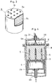
- Fig. 1 is an explanatory sectional view showing example of a heating apparatus used in the present invention
- the heating apparatus indicated at 1
- a cylindrical casing 2a and a lid 2b mounted for opening and closing (arrow O-C directions) to an opening (an upper opening in the figure) formed on one side of the casing 2a.
- a gas discharge pipe 2c is disposed in the lid 2b.
- an inner cylinder 3 capable of moving axially (in arrow U2-D2 directions) is received in the casing 2a, and a gas supply mechanism 4 which is movable axially (in arrow U1-D1 directions) is provided within the inner cylinder 3.
- a gas storage chamber 4A is formed in the interior of the gas supply mechanism 4, and a plurality of hollow tube-like gas nozzles 5 having such tips are projecting upwards through the inner cylinder 3, with a large number of gas ejection holes 5a being formed in the peripheral wall of each gas nozzle 5.
- a gas supply pipe 4b for the supply of heated inert gas is connected to the gas storage chamber 4A.
- An optional number (including unity) of gas nozzle 5 is provided in accordance with the size of an agglomerated preform B and for insertion into the preform. In the case where plural gas nozzles are used, it is desirable to arrange them at equal intervals. Provided, however, that they may be arranged at optional intervals while simulating the flow of gas in the preform B.
- the gas nozzles illustrated in the figure are straight tube-like, spiral tube-like nozzles may be inserted under rotation into the preform.
- the lid 2b is retracted to its open position, namely, upwards and the gas supply mechanism 4 is moved backward in the arrow D1 direction so that the tips of the gas nozzles 5 are completely retracted into the inner cylinder 3.
- the agglomerated preform B is placed into the casing 2a and the lid 2b is closed.
- heated inert gas is fed into the gas storage chamber 4A through the gas supply pipe 4b and is distributed to the gas nozzles 5, and the gas nozzles 5 are inserted into the preform B while the heated gas is allowed to jet from the gas ejection holes 5a.
- the heated gas is fed continuously or intermittently from the gas supply pipe 4b and is released upward while being dispersed to the interior of the preform B, whereby the preform B is heated uniformly and quickly from the interior thereof.
- the heated gas it is recommended to use an inert gas such as nitrogen gas or argon gas, but when the synthetic resin material used is difficult to undergo an oxidative deterioration, there may be used heated air for example.
- the gas which has passed through the preform B is collected in a chamber 2A formed in the interior of the lid 2b and is discharged from the discharge pipe 2c.
- the size of the chamber 2A can be set freely.
- the lid 2b When the whole of the preform B has been heated to a predetermined temperature in the above manner, the lid 2b is opened, the inner cylinder 3 is moved up in the direction of arrow U2, the preform B is discharged from the upper portion of the casing 2a and is conveyed to a molding apparatus such as a pressing apparatus for example.
- Fig. 2 is a flowchart showing an example of supplying heated gas to a plurality of heating apparatus 1
- the gas fed from a gas supply source 15 is pressurized by means of a blower 12 and them fed to a heater 11, in which the gas is heated up to a predetermined temperature (e.g. 220-240°C), then fed to the gas supply pipe of each heating apparatus 1.
- the used gas collected by the gas discharge pipe of the heating apparatus 1 is once stored in a tank 13, then cooled by a cooler 14 to a temperature at which the blower 12 can such the gas, and thereafter recirculated.
- a blower capable of sucking gas at a temperature of 150°C or so it is not necessary to use the cooler 14.
- the preform B is heated with only heated gas
- the preform is heated auxiliary also from the outer peripheral side, for example by providing a jacket-like heater 9 in the outer peripheral portion of the casing 2a, as indicated with broken lines, or by providing a face-form heater on the upper surface of the inner cylinder 3, the time required for heating can be further shortened.
- a total opening area Sr of the gas ejection holes 5a of the gas nozzles 5 can be selected optionally in accordance with the shape and size of the preform used.
- the above total opening area Sr is not smaller than (1/50) x Sn.
- FIG. 4 there is illustrated a heating apparatus having a structure of preventing the expansion of the preform B, in which pressing plate 6 capable of approaching and leaving the preform B is mounted to the lid 2b so that it can press the upper surface of the preform B received in the casing 2a.
- a large number of through holes are formed in the pressing plate 6, and heated gas passes through the through holes 6a and is collected into a gas discharge pipe 2c.
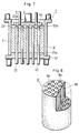
- some preform B comprises a solid film Bu about 1-3 mm thick formed on the outer surface of the preform and a mixture Bc of a synthetic resin powder and a reinforcing fiber wrapped in the solid film, as shown in Fig. 3.
- a preform B is applied as it is to the heating apparatus 1 shown in Fig. 1, the interior space defined by the solid film Bu of the preform B will be filled with heated gas, resulting in that a weak part of the solid film will burst, thus causing localization of the components of the mixture Bu, or causing a deflected flow of heated gas, leading to loss of uniformity in heating.
- the pressing plate 6 having holes 6a as in Fig.
- each gas nozzle 5 is smaller than the thickness in the height direction of the preform B, it may be rendered longer than the said preform thickness to the extent of its tip projecting from the preform B and breaking through the solid film Bu, thereby improving the passability of heated gas.
- a total opening area Sm of the vent holes B1 be one half or more of the total opening area Sr of the gas ejection holes 5a formed in the gas nozzles 5.
- a vertically movable bottom plate 21 having through holes 21a is provided under a casing 2, and a plurality of rod-like heaters 22 capable off being inserted into and removed from the through holes 21a are disposed under the bottom plate 21.
- a lid member 23 capable of approaching and leaving a preform B received in the casing 2 is provided in the upper portion of the casing, and through holes for insertion therethrough of tips 22a of the rod-like heater 22 are formed in the lid member 23.
- vertically movable upper lid 24 which are fitted on the tips of the rod-like heaters 22 and closes the said through holes.
- the number, thickness and length of the rod-like heaters 22 are selected suitably in accordance with the composite material to be heated.
- the bottom plate 21 is disposed under the casing 2
- a cylindrical preform B is loaded from the upper opening of the casing 2
- the lid member 23 and upper lid 24 are brought down from above until abutment with the upper surface of the preform B.
- the rod-like heaters 22 are moved upward and inserted into the preform B, as shown in Fig. 7.
- the lid member 23 may be disposed in a somewhat higher position to release the expansion of the preform caused by the rod-like heaters 22, or holes B2 corresponding to the rod-like heaters 22 may be formed beforehand in the preform B, as shown in Fig. 8.
- Such a preform B can also be used for the insertion therein of the gas nozzles 5, as described previously.
- the preform B When the rod-like heaters 22 are heated, the preform B is heated from the inner side and there is performed a uniform heating with small temperature gradient in the interior of the preform B. Further, if a sheet-like heater or the like is attached to each of the casing 2, lid member 23 and bottom plate 21, the preform B can be heated uniformly from both the inside and the outside.
- the rod-like heaters 22 are retracted and the preform B is moved to the upper portion of the casing 2 while be sandwiched in between the bottom plate 21 and the lid member 23, then the lid member 23 is retracted. Thereafter, the preform B is fed to a mold machine as in Fig. 9.
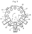
- Fig. 9 is a plan view showing a turntable type continuous heating system for heating preforms B continuously by heating apparatus 1 using gas nozzles 5 or rod-like heaters 22.
- a turntable 27 is provided with a plurality of heating apparatus 1 and is rotated by a driving roller 26. Along the outer peripheral edge of the turntable 27 there are disposed the driving roller 26 and guide rollers 25, as well as preform feeding machine A1 and discharging machine A4.
- a preform B is fed to a heating apparatus on the turntable 27 by the feeding machine A1, then in the position A2 the heaters or nozzles are inserted into the preform B, whereby the preform is heated until reaching the position A3.
- the thus-heated preform B is taken out from the heating apparatus 1 by means of the discharging machine A4 is fed thereby to the molding machine.
- the synthetic resin there may be selected a suitable one from among thermosetting resins and thermoplastic resins according to the use and characteristics required.
- examples of employable reinforcing fibers include various metallic fibers and whiskers in addition to most commonly used glass fibers and carbon fibers. If necessary, moreover, in the composite material containing such synthetic resin and reinforcing fiber there may be incorporated filler, antioxidant, stabilizer, coloring agent, plasticizer, antistatic agent, flame-retardant, etc.
- the method for forming the composite material into a preform is not limited at all, either.
- a conventional preforming method may be used as it is or after some modification.
- a composite material a uniform mixture consisting of 60 wt% polypropylene powder and 40 wt% short glass fibers was preformed into a short column shape (200 mm dia. 200 mm long), and a heating experiment was conducted.
- rod-like heaters there were used forty electric heating type rod-like heaters each 16 mm in diameter, and for heating the casing there was used a band heater from the outer surface side, while for heating the lid member and the bottom plate there were used plate heaters.
- the surface temperature was controlled to 260°C.
- nitrogen gas was passed through the heating apparatus 1.
- the temperature of the composite material rose to 220°C in about 2 minutes.
- the temperature difference in the preform was within ⁇ 2.5°C and thus very small. An extremely uniform heating was confirmed.
- heating was made from only the outer surface side of the casing, bottom plate and lid member in the same manner as above except that the heating using the rod-like heaters was omitted.
- the composite material temperature was raised to 220°C at the central portion thereof.
- the temperature of the surface side rose to 260°C and the synthetic resin melted, resulting in that it became difficult to remove the composite material from the heating apparatus.
- the temperature difference of about 40°C between the surface side and the central portion exerted a bad influence on the compression molding in the molding apparatus.
- the preform B is heated from the interior thereof without using the gas nozzles 5.
- the preform B there is used one having such holes B2 as shown in Fig. 8, or with such holes B2 being closed at one ends.
- These holes are formed by inserting heating needles arranged in conformity with the arrangement of the holes into a preform. It is preferable that the temperature of the needles be below the temperature at which the synthetic resin contained in the preform melts and adheres to the needles.
- the needle heating temperature be set in a temperature range in which the resin used does not adhere to the needles, taking the melting temperature of the resin into account.
- the needles may be held at room temperature, at which temperature, however, the holes may be closed by spring back of the glass fibers. It was found better for the needles to be heated to a certain extent for retaining the holes once formed.
- the preform now having such holes is loaded into the heating apparatus shown in Fig. 4, and nitrogen gas held at 240°C is blown directly (without using gas nozzles) into the holes of the preform for about 2 minutes.
- the heated nitrogen gas thus entered the holes is dispersed to the interior of the preform and thereafter discharged from the upper portion, whereby the preform is heated to about 200-220°C from the interior.
- This method is advantageous in that the heating can be done uniformly in a short time, and that since gas nozzles 5 or rod-like heaters 22 are not used there occurs neither adhesion nor clogging of molten resin, and handling is easy.
- an agglomerated preform containing a synthetic resin and a reinforcing fiber can be heated efficiently in a uniform temperature distribution throughout the whole thereof.
Landscapes
- Physics & Mathematics (AREA)
- Thermal Sciences (AREA)
- Engineering & Computer Science (AREA)
- Mechanical Engineering (AREA)
- Health & Medical Sciences (AREA)
- Oral & Maxillofacial Surgery (AREA)
- Chemical & Material Sciences (AREA)
- Composite Materials (AREA)
- Processing And Handling Of Plastics And Other Materials For Molding In General (AREA)
Abstract
Claims (6)
- Procédé de moulage d'un matériau composite renforcé de fibres comprenant un matériau de résine synthétique et de fibres de renforcement dispersées, procédé comprenant une étape de formage dudit matériau composite en une préforme agglomérée (B), de préchauffe de ladite préforme agglomérée (B) de l'intérieur et de moulage de la préforme agglomérée (B) préchauffée en une forme désirée,
procédé caractérisé en ce que ladite étape de préchauffe est effectuée à l'aide d'un moyen de chauffage choisi parmi une ou plusieurs buses de gaz (5) qui sont insérées dans ladite préforme agglomérée (B) et à travers lesquelles est soufflé un gaz à haute température pour chauffer ladite préforme agglomérée (B), un ou plusieurs dispositifs de chauffage en forme de tige (22) qui sont insérés dans ladite préforme agglomérée (B), et un ou plusieurs trous (B₂) possédant une extrémité fermée formée dans ladite préforme agglomérée (B) dans laquelle un gaz à haute température est soufflé pour chauffer ladite préforme agglomérée (B). - Procédé de moulage selon la revendication 1, selon lequel ledit moyen de chauffage comprend une ou plusieurs buses de gaz (5) qui sont insérées dans ladite préforme agglomérée (B) et à travers lesquelles est soufflé un gaz à haute température dans la préforme agglomérée (B).
- Procédé de moulage selon la revendication 2, selon lequel chacune desdites buses de gaz comprend une partie d'extrémité pointue et une partie de corps présentant un ou plusieurs orifices d'éjection de gaz (5a) à travers lesquels est éjecté un gaz à haute température pour chauffer ladite préforme agglomérée (B).
- Procédé de moulage selon la revendication 1, selon ledit moyen de chauffage comprend un ou plusieurs dispositifs de chauffage en forme de tige (22) qui sont insérés dans ladite préforme agglomérée (B).
- Procédé de moulage selon la revendication 1, selon lequel ledit moyen de chauffage comprend un ou plusieurs trous (B₂) formés dans ladite préforme agglomérée (B), possédant chacun une extrémité fermée, dans lesquels est soufflé un gaz de haute température pour chauffer la préforme agglomérée (B).
- Procédé de moulage selon la revendication 5, selon lequel lesdits un ou plusieurs trous sont formés par insertion d'une ou de plusieurs tiges chauffées dans ladite préforme agglomérée (B), lesdites tiges chauffées ayant été chauffées à une température inférieure à celle où le matériau de résine synthétique fond et adhère aux tiges.
Applications Claiming Priority (9)
| Application Number | Priority Date | Filing Date | Title |
|---|---|---|---|
| JP32283689A JPH03182307A (ja) | 1989-12-12 | 1989-12-12 | 繊維強化複合材料の予備成形体 |
| JP32283889A JPH03182309A (ja) | 1989-12-12 | 1989-12-12 | 繊維強化複合材料の加熱方法 |
| JP32283789A JPH03182308A (ja) | 1989-12-12 | 1989-12-12 | 繊維強化複合材料の加熱方法 |
| JP322838/89 | 1989-12-12 | ||
| JP32283989A JPH03182310A (ja) | 1989-12-12 | 1989-12-12 | 繊維強化複合材料の加熱方法 |
| JP322839/89 | 1989-12-12 | ||
| JP322836/89 | 1989-12-12 | ||
| JP322837/89 | 1989-12-12 | ||
| PCT/JP1990/001628 WO1991008883A1 (fr) | 1989-12-12 | 1990-12-12 | Procede de moulage d'un materiau composite renforce par des fibres et corps premoule a base d'un tel materiau |
Publications (3)
| Publication Number | Publication Date |
|---|---|
| EP0457917A1 EP0457917A1 (fr) | 1991-11-27 |
| EP0457917A4 EP0457917A4 (en) | 1992-06-03 |
| EP0457917B1 true EP0457917B1 (fr) | 1995-08-02 |
Family
ID=27480288
Family Applications (1)
| Application Number | Title | Priority Date | Filing Date |
|---|---|---|---|
| EP91900325A Expired - Lifetime EP0457917B1 (fr) | 1989-12-12 | 1990-12-12 | Procede de moulage d'un coprs premoule en materiau composite renforce par des fibres |
Country Status (4)
| Country | Link |
|---|---|
| US (1) | US5283026A (fr) |
| EP (1) | EP0457917B1 (fr) |
| DE (1) | DE69021377T2 (fr) |
| WO (1) | WO1991008883A1 (fr) |
Families Citing this family (23)
| Publication number | Priority date | Publication date | Assignee | Title |
|---|---|---|---|---|
| US5458838A (en) * | 1992-03-11 | 1995-10-17 | Kabushiki Kaisha Kobe Seiko Sho | Heating and extruding method for bulk preform |
| AU668470B2 (en) * | 1993-07-12 | 1996-05-02 | Seaward International, Inc. | Elongated structural member and method and apparatus for making same |
| US5697421A (en) * | 1993-09-23 | 1997-12-16 | University Of Cincinnati | Infrared pressureless infiltration of composites |
| US5591784A (en) * | 1994-06-17 | 1997-01-07 | Three Bond Co., Ltd. | Curing of fiber-reinforced composite structures |
| DE19718505A1 (de) * | 1997-05-02 | 1998-11-05 | Huels Chemische Werke Ag | Verfahren zum Thermoformen von Rohren mittels eines HF-Feldes |
| US6682619B2 (en) | 2001-07-17 | 2004-01-27 | Sikorsky Aircraft Corporation | Composite pre-preg ply having tailored dielectrical properties and method of fabrication thereof |
| DE10217391A1 (de) * | 2002-04-18 | 2003-11-13 | Siemens Ag | Stapelbare Behälter |
| WO2007140469A2 (fr) * | 2006-05-31 | 2007-12-06 | The Dow Chemical Company | Additifs destinés à l'utilisation d'énergie micro-onde pour chauffer sélectivement des systèmes polymères thermoplastiques |
| AT506068B1 (de) * | 2008-03-12 | 2009-06-15 | Franz Stransky Ges M B H | Werkzeug zur herstellung von kunststoffen |
| JP5710592B2 (ja) * | 2009-04-21 | 2015-04-30 | コーニンクレッカ フィリップス エヌ ヴェ | プレフォームのボディを加熱する加熱システム及び方法 |
| US20110031660A1 (en) * | 2009-08-05 | 2011-02-10 | Huff Norman T | Method of forming a muffler preform |
| US8623263B2 (en) * | 2009-08-05 | 2014-01-07 | Ocv Intellectual Capital, Llc | Process for curing a porous muffler preform |
| CN103057013B (zh) * | 2013-01-09 | 2015-07-29 | 南京航空航天大学 | 一种纤维增强树脂基复合材料的加热固化装置及方法 |
| US10005246B2 (en) * | 2013-08-22 | 2018-06-26 | Faurecia Interior Systems, Inc. | Methods for making interior panels for motor vehicles |
| GB2535193A (en) * | 2015-02-12 | 2016-08-17 | Zodiac Seats Uk Ltd | Tool for curing a composite component |
| US10071521B2 (en) * | 2015-12-22 | 2018-09-11 | Mks Instruments, Inc. | Method and apparatus for processing dielectric materials using microwave energy |
| US11007674B2 (en) * | 2015-12-25 | 2021-05-18 | Teijin Limited | Method for manufacturing heated molding material and device for heating molding material |
| JP6604322B2 (ja) * | 2016-12-28 | 2019-11-13 | トヨタ自動車株式会社 | 繊維強化樹脂成形体の製造方法 |
| US11167466B2 (en) | 2017-12-13 | 2021-11-09 | Kent Byron | Method of forming polypropylene bottles |
| LU100718B1 (fr) * | 2018-03-01 | 2019-10-01 | Cristalux Int Sarl | Matelas en matiere thermoplastique, procede pour sa fabrication et utilisations de celui-ci |
| DE102018110238A1 (de) * | 2018-04-27 | 2019-10-31 | Fox Velution Gmbh | Werkzeug zur Verarbeitung von Kunststoffpartikelmaterial zur Herstellung eines Partikelschaumbauteils |
| US11639304B2 (en) | 2020-02-07 | 2023-05-02 | Raytheon Technologies Corporation | Method of fabricating a glass-ceramic matrix composite |
| DE102023207470A1 (de) * | 2023-08-03 | 2025-02-06 | Volkswagen Aktiengesellschaft | Werkzeuganordnung zur Herstellung eines Bauteils, vorzugsweise zur Herstellung eines Polymerschaumbauteils, sowie Verfahren zur Herstellung eines Bauteils, vorzugsweise zur Herstellung eines Polymerschaumbauteils |
Citations (1)
| Publication number | Priority date | Publication date | Assignee | Title |
|---|---|---|---|---|
| EP0278363A2 (fr) * | 1987-02-10 | 1988-08-17 | Menzolit GmbH | Procédé et dispositif pour la préparation de matériau thermoplastique renforcé avec des fibres pour la fabrication d'articles moulés |
Family Cites Families (42)
| Publication number | Priority date | Publication date | Assignee | Title |
|---|---|---|---|---|
| US598282A (en) * | 1898-02-01 | Clay-steamer | ||
| CA703789A (en) * | 1965-02-16 | Dietzsch Hans-Joachim | Producing material of honeycomb structure | |
| US2289177A (en) * | 1939-02-09 | 1942-07-07 | Perfotex Company | Composite foraminous material |
| US2244550A (en) * | 1940-03-11 | 1941-06-03 | Chandler Frank Jermain | Perforating method and apparatus |
| BE488915A (fr) * | 1948-05-08 | |||
| US2533609A (en) * | 1949-03-19 | 1950-12-12 | Bell Aircraft Corp | Process for manufacturing minutely orificed articles |
| US2707804A (en) * | 1951-04-28 | 1955-05-10 | Us Rubber Co | Apparatus for steam curing frothed latex |
| US2900109A (en) * | 1957-04-29 | 1959-08-18 | Fibreboard Paper Products Corp | Method for preheating cementitious insulating material |
| US3005491A (en) * | 1958-10-08 | 1961-10-24 | Diamond National Corp | Chamberless mold and process of making same |
| NL265964A (fr) * | 1962-09-28 | |||
| US3391846A (en) * | 1963-08-08 | 1968-07-09 | Du Pont | Heating with antiferromagnetic particles in a high frequency magnetic field |
| US3405204A (en) * | 1964-07-23 | 1968-10-08 | Du Pont | Process of vulcanizing with ammonia a chlorosulfonated polyethylene coating containing an active metal oxide |
| US3477961A (en) * | 1966-03-09 | 1969-11-11 | Chevron Res | Poly-alpha-olefin iron-nickel alloy mixtures |
| DE1784801A1 (de) * | 1968-09-20 | 1971-12-02 | Astik Werk Guenther Jaehne Bsb | Verfahren und Einrichtung zur Herstellung von gelochten bzw.mit Schlitzen oder anderen OEffnungen versehenen faserbewaehrten Platten oder Formkoerpern hoher Festigkeit |
| US3650866A (en) * | 1969-10-09 | 1972-03-21 | Exxon Research Engineering Co | Increasing strip tensile strength of melt blown nonwoven polypropylene mats of high tear resistance |
| US3704194A (en) * | 1970-07-02 | 1972-11-28 | Gen Electric | Perforated reinforced plastic member and method for making |
| US3719736A (en) * | 1970-10-08 | 1973-03-06 | Gen Foods Corp | Method of producing perforated plastic film |
| US3787546A (en) * | 1970-12-21 | 1974-01-22 | Gen Electric | Method for making a perforated plastic article |
| US3952402A (en) * | 1971-02-02 | 1976-04-27 | Mero Ag | Composite structural panel and process of making |
| US3919369A (en) * | 1971-03-08 | 1975-11-11 | American Filtrona Corp | Method of manufacturing a self-contained low pressure drop filter |
| US3763293A (en) * | 1971-06-09 | 1973-10-02 | Bischoff Chemical Corp | Process of molding giant articles of structured plastic |
| US3849527A (en) * | 1971-06-29 | 1974-11-19 | Drostholm F H | Method for making reinforced or filled resin products |
| US3850723A (en) * | 1971-09-20 | 1974-11-26 | Ppg Industries Inc | Method of making a stampable reinforced sheet |
| US4218276A (en) * | 1972-03-31 | 1980-08-19 | Avco Corporation | Method for making 3-D structures |
| US4251477A (en) * | 1977-10-03 | 1981-02-17 | Plymouth Locomotive Works, Inc. | On-line fluid injecting method |
| US4132519A (en) * | 1977-10-28 | 1979-01-02 | Rohr Industries, Inc. | Controlled porosity of uncured reinforced thermo-setting plastic material |
| FR2433003A1 (fr) * | 1978-08-08 | 1980-03-07 | Commissariat Energie Atomique | Procede de fabrication d'un materiau renforce par une structure textile tridimensionnelle |
| FR2467092A1 (fr) * | 1979-10-11 | 1981-04-17 | Hutchinson Mapa | Perfectionnements apportes aux procedes de fabrication de chambres du type dit increvable pour roues de vehicules et analogues, et chambres increvables ainsi obtenues |
| JPS59118418A (ja) * | 1982-12-24 | 1984-07-09 | Toshiba Corp | 樹脂成形装置 |
| US4545837A (en) * | 1983-05-31 | 1985-10-08 | United Technologies Corporation | Molded-in composite bushings |
| JPS59220932A (ja) * | 1983-05-31 | 1984-12-12 | Toshiba Corp | 半導体素子用モ−ルド樹脂の予熱装置 |
| US4486372A (en) * | 1983-09-30 | 1984-12-04 | Rohr Industries, Inc. | Method for fabricating contoured perforated composite laminate structure |
| US4696711A (en) * | 1983-09-30 | 1987-09-29 | Mcdonnell Douglas Corporation | Method for forming holes in composites |
| US4652415A (en) * | 1985-02-11 | 1987-03-24 | General Motors Corporation | Method of manufacture of a molded friction pad |
| US4767799A (en) * | 1985-03-04 | 1988-08-30 | Phillips Petroleum Company | Radio frequency energy sensitized compositions and method for sensitizing compositions to radio frequency energy |
| US4693856A (en) * | 1985-04-22 | 1987-09-15 | The Dow Chemical Company | Method and apparatus for the preparation of foamed thermoplastic articles |
| EP0223039B1 (fr) * | 1985-10-16 | 1990-08-08 | Toyota Jidosha Kabushiki Kaisha | Méthode pour produire une pièce en bois moulée |
| JPS62242507A (ja) * | 1986-04-16 | 1987-10-23 | Kuraudo:Kk | 廃プラスチツク熱処理方法 |
| US4950532A (en) * | 1986-10-30 | 1990-08-21 | Azdel, Inc. | Process for producing glass fiber reinforced thermoplastic compression molded materials and said molded materials |
| US5047198A (en) * | 1988-03-30 | 1991-09-10 | General Electric Company | Compression molding of composite parts on hot mold surfaces with a short cycle time |
| US4980384A (en) * | 1988-09-05 | 1990-12-25 | Shin-Etsu Chemical Co., Ltd. | Foamable silicone rubber composition and method for curing the same |
| US5066442A (en) * | 1989-02-28 | 1991-11-19 | Massachusetts Institute Of Technology | Method of producing a composite article |
-
1990
- 1990-12-12 EP EP91900325A patent/EP0457917B1/fr not_active Expired - Lifetime
- 1990-12-12 US US07/741,515 patent/US5283026A/en not_active Expired - Fee Related
- 1990-12-12 WO PCT/JP1990/001628 patent/WO1991008883A1/fr not_active Ceased
- 1990-12-12 DE DE69021377T patent/DE69021377T2/de not_active Expired - Fee Related
Patent Citations (1)
| Publication number | Priority date | Publication date | Assignee | Title |
|---|---|---|---|---|
| EP0278363A2 (fr) * | 1987-02-10 | 1988-08-17 | Menzolit GmbH | Procédé et dispositif pour la préparation de matériau thermoplastique renforcé avec des fibres pour la fabrication d'articles moulés |
Also Published As
| Publication number | Publication date |
|---|---|
| US5283026A (en) | 1994-02-01 |
| DE69021377D1 (de) | 1995-09-07 |
| DE69021377T2 (de) | 1996-01-25 |
| EP0457917A4 (en) | 1992-06-03 |
| EP0457917A1 (fr) | 1991-11-27 |
| WO1991008883A1 (fr) | 1991-06-27 |
Similar Documents
| Publication | Publication Date | Title |
|---|---|---|
| EP0457917B1 (fr) | Procede de moulage d'un coprs premoule en materiau composite renforce par des fibres | |
| KR930000742B1 (ko) | 인발 성형방법, 그 장치 및 그 제품 | |
| US5506029A (en) | Fiber reinforced thermoplastic resin shaped article | |
| US4239727A (en) | Method and apparatus for thermoforming thermoplastic foam articles | |
| EP1729949B1 (fr) | Procede de production de corps moules en matiere thermoplastique | |
| US5747548A (en) | Compartmented thermoplastic pellets | |
| DE3124523C2 (de) | Vorrichtung zum Herstellen von Hohlkörpern aus thermoplastischem Kunststoff | |
| CA2248262C (fr) | Procede de moulage par compression | |
| KR100632164B1 (ko) | 섬유-강화 열가소성 수지 성형제품을 제조하기 위한 방법및 그 방법에 의해 제조된 성형제품 | |
| US7122146B2 (en) | Injection molding of polymers by microwave heating | |
| CA1120220A (fr) | Appareil et methode de moulage par soufflage | |
| TW202210269A (zh) | 快速熱循環模製 | |
| KR20030014143A (ko) | 안전 슈즈용 장섬유 강화 열가소성 수지로 이루어진 토우캡 및 그의 제조 방법 | |
| JP3234877B2 (ja) | 繊維強化樹脂ペレットの製造方法 | |
| JP3572823B2 (ja) | 繊維強化熱可塑性樹脂成形体の製造方法 | |
| EP0743165B1 (fr) | Procédé et appareil pour le moulage de matériaux thermoplastiques renforcés | |
| JPH03182308A (ja) | 繊維強化複合材料の加熱方法 | |
| JPH06102335B2 (ja) | 繊維強化複合材料予備成形体の加熱方法 | |
| JPH04153008A (ja) | 繊維強化複合材料の加熱方法 | |
| JPS63115708A (ja) | 加圧成形方法およびその装置 | |
| CN1307032C (zh) | 提高压制成型产品质量的方法及其装置 | |
| US12157255B1 (en) | System and method for molding stock shapes | |
| JP7568322B1 (ja) | 不織布製造装置、及び不織布製造方法 | |
| US20070235901A1 (en) | Apparatus and method for molding polymer parts by displacement-injection molding | |
| CA2085441C (fr) | Article forme en resine thermoplastique renforcee de fibres, et sa preparation |
Legal Events
| Date | Code | Title | Description |
|---|---|---|---|
| PUAI | Public reference made under article 153(3) epc to a published international application that has entered the european phase |
Free format text: ORIGINAL CODE: 0009012 |
|
| 17P | Request for examination filed |
Effective date: 19910911 |
|
| AK | Designated contracting states |
Kind code of ref document: A1 Designated state(s): DE FR GB |
|
| A4 | Supplementary search report drawn up and despatched |
Effective date: 19920413 |
|
| AK | Designated contracting states |
Kind code of ref document: A4 Designated state(s): DE FR GB |
|
| 17Q | First examination report despatched |
Effective date: 19931015 |
|
| GRAA | (expected) grant |
Free format text: ORIGINAL CODE: 0009210 |
|
| AK | Designated contracting states |
Kind code of ref document: B1 Designated state(s): DE FR GB |
|
| ET | Fr: translation filed | ||
| REF | Corresponds to: |
Ref document number: 69021377 Country of ref document: DE Date of ref document: 19950907 |
|
| PLBE | No opposition filed within time limit |
Free format text: ORIGINAL CODE: 0009261 |
|
| STAA | Information on the status of an ep patent application or granted ep patent |
Free format text: STATUS: NO OPPOSITION FILED WITHIN TIME LIMIT |
|
| 26N | No opposition filed | ||
| PGFP | Annual fee paid to national office [announced via postgrant information from national office to epo] |
Ref country code: GB Payment date: 19971203 Year of fee payment: 8 |
|
| PGFP | Annual fee paid to national office [announced via postgrant information from national office to epo] |
Ref country code: FR Payment date: 19971209 Year of fee payment: 8 |
|
| PG25 | Lapsed in a contracting state [announced via postgrant information from national office to epo] |
Ref country code: GB Free format text: LAPSE BECAUSE OF NON-PAYMENT OF DUE FEES Effective date: 19981212 |
|
| PGFP | Annual fee paid to national office [announced via postgrant information from national office to epo] |
Ref country code: DE Payment date: 19981221 Year of fee payment: 9 |
|
| GBPC | Gb: european patent ceased through non-payment of renewal fee |
Effective date: 19981212 |
|
| PG25 | Lapsed in a contracting state [announced via postgrant information from national office to epo] |
Ref country code: FR Free format text: LAPSE BECAUSE OF NON-PAYMENT OF DUE FEES Effective date: 19990831 |
|
| REG | Reference to a national code |
Ref country code: FR Ref legal event code: ST |
|
| PG25 | Lapsed in a contracting state [announced via postgrant information from national office to epo] |
Ref country code: DE Free format text: LAPSE BECAUSE OF NON-PAYMENT OF DUE FEES Effective date: 20001003 |