EP0457944A1 - Dalle pour construire un faux-plancher pour câble - Google Patents
Dalle pour construire un faux-plancher pour câble Download PDFInfo
- Publication number
- EP0457944A1 EP0457944A1 EP90109788A EP90109788A EP0457944A1 EP 0457944 A1 EP0457944 A1 EP 0457944A1 EP 90109788 A EP90109788 A EP 90109788A EP 90109788 A EP90109788 A EP 90109788A EP 0457944 A1 EP0457944 A1 EP 0457944A1
- Authority
- EP
- European Patent Office
- Prior art keywords
- end faces
- channels
- molding plate
- plate according
- electrically conductive
- Prior art date
- Legal status (The legal status is an assumption and is not a legal conclusion. Google has not performed a legal analysis and makes no representation as to the accuracy of the status listed.)
- Granted
Links
- 239000012799 electrically-conductive coating Substances 0.000 claims abstract description 7
- 238000000465 moulding Methods 0.000 claims description 14
- 238000000576 coating method Methods 0.000 claims description 8
- 239000011248 coating agent Substances 0.000 claims description 7
- OKTJSMMVPCPJKN-UHFFFAOYSA-N Carbon Chemical compound [C] OKTJSMMVPCPJKN-UHFFFAOYSA-N 0.000 claims description 5
- 239000010439 graphite Substances 0.000 claims description 5
- 229910002804 graphite Inorganic materials 0.000 claims description 5
- 230000000295 complement effect Effects 0.000 claims description 3
- 238000004519 manufacturing process Methods 0.000 claims description 3
- 239000002184 metal Substances 0.000 claims description 3
- 230000015572 biosynthetic process Effects 0.000 claims 1
- 238000003475 lamination Methods 0.000 claims 1
- 230000005684 electric field Effects 0.000 abstract description 3
- 238000010276 construction Methods 0.000 description 5
- 239000011810 insulating material Substances 0.000 description 2
- 239000012774 insulation material Substances 0.000 description 2
- 239000000463 material Substances 0.000 description 2
- 239000007921 spray Substances 0.000 description 2
- 238000005507 spraying Methods 0.000 description 2
- 235000013162 Cocos nucifera Nutrition 0.000 description 1
- 244000060011 Cocos nucifera Species 0.000 description 1
- 239000004793 Polystyrene Substances 0.000 description 1
- 229920002522 Wood fibre Polymers 0.000 description 1
- 239000007799 cork Substances 0.000 description 1
- 230000005574 cross-species transmission Effects 0.000 description 1
- 238000010790 dilution Methods 0.000 description 1
- 239000012895 dilution Substances 0.000 description 1
- 239000003000 extruded plastic Substances 0.000 description 1
- 239000000835 fiber Substances 0.000 description 1
- 239000006260 foam Substances 0.000 description 1
- 239000011888 foil Substances 0.000 description 1
- 239000011491 glass wool Substances 0.000 description 1
- 230000007257 malfunction Effects 0.000 description 1
- 239000002557 mineral fiber Substances 0.000 description 1
- 239000011490 mineral wool Substances 0.000 description 1
- 229920002223 polystyrene Polymers 0.000 description 1
- 150000003839 salts Chemical class 0.000 description 1
- 239000007787 solid Substances 0.000 description 1
- XLYOFNOQVPJJNP-UHFFFAOYSA-N water Substances O XLYOFNOQVPJJNP-UHFFFAOYSA-N 0.000 description 1
- 239000002025 wood fiber Substances 0.000 description 1
Images

Classifications
-
- E—FIXED CONSTRUCTIONS
- E04—BUILDING
- E04F—FINISHING WORK ON BUILDINGS, e.g. STAIRS, FLOORS
- E04F15/00—Flooring
- E04F15/02—Flooring or floor layers composed of a number of similar elements
- E04F15/024—Sectional false floors, e.g. computer floors
- E04F15/02405—Floor panels
- E04F15/02411—Floor panels with integrated feet
-
- H—ELECTRICITY
- H02—GENERATION; CONVERSION OR DISTRIBUTION OF ELECTRIC POWER
- H02G—INSTALLATION OF ELECTRIC CABLES OR LINES, OR OF COMBINED OPTICAL AND ELECTRIC CABLES OR LINES
- H02G3/00—Installations of electric cables or lines or protective tubing therefor in or on buildings, equivalent structures or vehicles
- H02G3/28—Installations of cables, lines, or separate protective tubing therefor in conduits or ducts pre-established in walls, ceilings or floors
- H02G3/283—Installations of cables, lines, or separate protective tubing therefor in conduits or ducts pre-established in walls, ceilings or floors in floors
- H02G3/285—Installations of cables, lines, or separate protective tubing therefor in conduits or ducts pre-established in walls, ceilings or floors in floors in modular floors, e.g. access floors
Definitions
- the invention relates to a mold plate for the production of a cable floor.
- Such a molding plate is known from DE utility model G 86 04 531.8 of the applicant.
- the molding plate is made from an insulating material into which the channels are milled from the underside.
- a form plate for the production of a cable base serves to solve this task, with: an underside which is in use rests on a building ceiling or structure; an upper surface to which a walking layer or floor construction is applied in use and which forms a surface substantially parallel to the lower surface; two end faces which are perpendicular to the underside or top side and are likewise essentially parallel and are separated from one another by the body of the molding plate; two side surfaces connecting the end faces; wherein channels are arranged in the body, which are open to the underside of the mold plate.
- any solid insulation material is suitable as the material for the molding plate, e.g. polystyrene, wood fiber, mineral fiber (such as rock wool or glass wool etc.), cork, bound natural fibers (e.g. coconut) or extruded plastic foams that have a closed-cell structure.
- An electrically conductive graphite coating for example, which is sold by Acheson under the trademark ELECTRODAG® 5405A, is suitable as the conductive coating.
- This graphite coating can be applied in a layer thickness of 25 to 50 ⁇ m, the application being carried out by spraying on with a spray pressure of 2 to 2.5 bar and a nozzle diameter of 1 to 2 mm.
- the resistance of the hardened layer is 20 ⁇ / m2 at 25 ⁇ m layer thickness.
- the continuous operating temperature is 150 ° C.
- Other suitable conductive coatings are, for example, metal foils, wire mesh or the like.
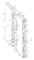
- Figure 1 shows a mold plate 1 according to the invention with two dash-dotted dividing lines A, which are intended to indicate that the mold plate 1 in one embodiment can end straight as shown in Figure 2, while in another embodiment several similar mold plates are laid together to form a cable floor. This will be discussed in more detail later.
- the mold plate 1 which can be seen in FIG. 1 has a body 6 which consists of an insulating material.
- the materials mentioned above can be used as insulation materials.
- the body 6 forms a plate with a width of approximately 500 mm, a length of approximately 1000 mm and a height of approximately 50 mm. It is clear that the dimensions can be easily adapted to the respective application.
- the mold plate 1 accordingly has an underside 2, an upper side 3 parallel thereto, two end faces 4 and 5, which are generally parallel to one another, and two side faces 7 and 8 connecting the end faces.
- the end faces 4 and 5 therefore lie just like the side faces 7 and 8 in Distance from each other.
- the mold plate 1 has the shape of a rectangle.
- Channels 9 are formed in the body 6 of the mold plate 1 from the underside 2 and extend over the entire length of the mold plate 1 and at a distance are arranged to each other.
- the channels 9 run parallel to one another and also parallel to the side surfaces 7 and 8.
- the channels 9 are open towards the underside 2.
- each mold plate 1 is provided with toothings 11 and 12 which are complementary to one another.
- toothings 11 and 12 which are complementary to one another.
- 4 recesses 18 are provided in the first end face
- 5 recesses 18 ' are formed in the corresponding region of the other end face.
- the toothing 11 and 12 in the end faces 4 and 5 of the mold plate 1 also form a first step 15, which is measured from the bottom 2 higher than the apex 17 of the channels 9.
- the channels 9 generally all have the same height, so that their apex 17 are approximately at the same height.
- the fact that the stage 15 is higher than the apex 17 of the channels 9 ensures that the teeth 11 and 12 do not cut into the channels 9 and thereby open them upwards.
- a second step 16 is provided in the side surfaces 7 and 8, which is also complementary to that in each case is formed in the opposite side surface 7 and 8 step 16 '.
- similar shaped plates 1 can, in principle, be placed close together without a gap being formed.
- the step 16, 16 ' is each formed by a projection 20 and a recess 21 which run parallel to the longitudinal extent of the side surface 7 and 8, respectively.
- the projection 20 is located on the left side surface 7 in the region of the upper side 3 of the mold plate 1, while it is provided on the right side surface 8 in the region of the lower side 2.
- Figure 2 shows two mold plates 1 and 1 'according to the invention in an exploded view, which indicate the structure of a floor structure.
- the upper or rear mold plate 1 corresponds to the mold plate shown in Figure 1.
- the one below the molding plate 1 ' is intended to indicate an edge element in which the front end face 4' is bluntly cut off so that there is no more toothing there.
- FIG. 2 shows how the toothings 11 and 12 of the mold plates 1 and 1 'can interlock and that the channels 9 extend in alignment through the entire floor construction.
- the inner sides 10 of the channels 9, the end faces 4 and 5 including their teeth 11 and 12 and the side surfaces 7 and 8 with their teeth 13 and 14 are provided with an electrically conductive coating.
- the electrically conductive coating is a graphite coating, for example of the type ELECTRODAG ® 5405 A from Fira Acheson. It provides excellent shielding against electromagnetic interference and also protection against electrostatic discharge. Even when exposed to heat, cold, moisture or salt, the coating maintains its low electrical resistance of around 20 ⁇ / m2 with a layer thickness of 25 ⁇ m.
- ELECTRODAG® 5405 A is applied by simple spraying, for example after additional dilution with water. The recommended spray pressure is 2 to 2.5 bar with a nozzle diameter of 1 to 2 mm. Further Details can be found in the product information from Acheson.
- the entire underside and the interfaces to adjacent mold plates are electrically conductive, so that they form a so-called Faraday cage for the cables and lines laid therein or below, which shields from one another the cables or lines which run in adjacent or spaced-apart channels.
Landscapes
- Engineering & Computer Science (AREA)
- Architecture (AREA)
- Civil Engineering (AREA)
- Structural Engineering (AREA)
- General Engineering & Computer Science (AREA)
- Floor Finish (AREA)
- Details Of Indoor Wiring (AREA)
- Installation Of Indoor Wiring (AREA)
Priority Applications (3)
| Application Number | Priority Date | Filing Date | Title |
|---|---|---|---|
| DE59007155T DE59007155D1 (de) | 1990-05-23 | 1990-05-23 | Formplatte für die Herstellung eines Kabelbodens. |
| AT90109788T ATE111650T1 (de) | 1990-05-23 | 1990-05-23 | Formplatte für die herstellung eines kabelbodens. |
| EP90109788A EP0457944B1 (fr) | 1990-05-23 | 1990-05-23 | Dalle pour construire un faux-plancher pour câble |
Applications Claiming Priority (1)
| Application Number | Priority Date | Filing Date | Title |
|---|---|---|---|
| EP90109788A EP0457944B1 (fr) | 1990-05-23 | 1990-05-23 | Dalle pour construire un faux-plancher pour câble |
Publications (2)
| Publication Number | Publication Date |
|---|---|
| EP0457944A1 true EP0457944A1 (fr) | 1991-11-27 |
| EP0457944B1 EP0457944B1 (fr) | 1994-09-14 |
Family
ID=8204016
Family Applications (1)
| Application Number | Title | Priority Date | Filing Date |
|---|---|---|---|
| EP90109788A Expired - Lifetime EP0457944B1 (fr) | 1990-05-23 | 1990-05-23 | Dalle pour construire un faux-plancher pour câble |
Country Status (3)
| Country | Link |
|---|---|
| EP (1) | EP0457944B1 (fr) |
| AT (1) | ATE111650T1 (fr) |
| DE (1) | DE59007155D1 (fr) |
Cited By (3)
| Publication number | Priority date | Publication date | Assignee | Title |
|---|---|---|---|---|
| WO2007006151A1 (fr) * | 2005-07-07 | 2007-01-18 | Ouellet Andre | Carreau de pont à lame de soutien |
| EP1621673A3 (fr) * | 2004-07-30 | 2008-02-27 | Pooltechnics B.V. | Revêtement de sol |
| EP2887479A1 (fr) * | 2013-12-18 | 2015-06-24 | Tarkett GDL S.A. | Plaque destinée à être appliquée sur une surface de construction et procédé d'installation de câbles dans un bâtiment |
Citations (3)
| Publication number | Priority date | Publication date | Assignee | Title |
|---|---|---|---|---|
| DE3041624A1 (de) * | 1980-11-05 | 1982-06-09 | Werner T. Dipl.-Ing. 3000 Hannover Huss | Pflasterung fuer hof- und hallenflaechen, verfahren zur herstellung dieser pflasterung und werkstein zur herstellung dieser pflasterung |
| EP0263583A2 (fr) * | 1986-10-07 | 1988-04-13 | Philip J. Forde | Plancher d'accès |
| WO1988003207A1 (fr) * | 1986-10-22 | 1988-05-05 | Michael David Boyd | Panneaux de sol creux modulaires a gaine solidaire |
-
1990
- 1990-05-23 EP EP90109788A patent/EP0457944B1/fr not_active Expired - Lifetime
- 1990-05-23 DE DE59007155T patent/DE59007155D1/de not_active Expired - Fee Related
- 1990-05-23 AT AT90109788T patent/ATE111650T1/de not_active IP Right Cessation
Patent Citations (3)
| Publication number | Priority date | Publication date | Assignee | Title |
|---|---|---|---|---|
| DE3041624A1 (de) * | 1980-11-05 | 1982-06-09 | Werner T. Dipl.-Ing. 3000 Hannover Huss | Pflasterung fuer hof- und hallenflaechen, verfahren zur herstellung dieser pflasterung und werkstein zur herstellung dieser pflasterung |
| EP0263583A2 (fr) * | 1986-10-07 | 1988-04-13 | Philip J. Forde | Plancher d'accès |
| WO1988003207A1 (fr) * | 1986-10-22 | 1988-05-05 | Michael David Boyd | Panneaux de sol creux modulaires a gaine solidaire |
Cited By (3)
| Publication number | Priority date | Publication date | Assignee | Title |
|---|---|---|---|---|
| EP1621673A3 (fr) * | 2004-07-30 | 2008-02-27 | Pooltechnics B.V. | Revêtement de sol |
| WO2007006151A1 (fr) * | 2005-07-07 | 2007-01-18 | Ouellet Andre | Carreau de pont à lame de soutien |
| EP2887479A1 (fr) * | 2013-12-18 | 2015-06-24 | Tarkett GDL S.A. | Plaque destinée à être appliquée sur une surface de construction et procédé d'installation de câbles dans un bâtiment |
Also Published As
| Publication number | Publication date |
|---|---|
| DE59007155D1 (de) | 1994-10-20 |
| ATE111650T1 (de) | 1994-09-15 |
| EP0457944B1 (fr) | 1994-09-14 |
Similar Documents
| Publication | Publication Date | Title |
|---|---|---|
| DE3890470C2 (de) | Kabel mit niedrigem Profil für verdrillte Drahtpaare | |
| EP1725720B1 (fr) | Panneau pour revêtement | |
| DE69120592T2 (de) | Kabelmodul | |
| DE2658708A1 (de) | Fuehrung fuer elektrische verteilungs- und fernmeldeleitungen in gebaeuden | |
| DE69226879T2 (de) | Elektrische Verbinder | |
| DE2441013C3 (de) | Verbinderblock fur Hauptverteilerrahmen in Modulausführung | |
| EP0735623A2 (fr) | Connecteur électrique | |
| DE2844523A1 (de) | Bewaesserungseinrichtung | |
| EP0457944B1 (fr) | Dalle pour construire un faux-plancher pour câble | |
| DE3942520A1 (de) | Aus einem metallischen werkstoff bestehende anschlussklemme | |
| DE102012222364A1 (de) | Steckverbinder und Vorrichtung mit einem solchen Steckverbinder | |
| DE4244424C2 (de) | Installationsboden | |
| DE602004012175T2 (de) | Verfahren zur Herstellung von Kontaktstreifen für Verbinder von elektrischen Geräten | |
| EP0609651A1 (fr) | Elément de façade | |
| DE2123152B2 (de) | Verbindungsstueck fuer stromentnahmeschienen mit u-foermigem querschnitt der tragschiene | |
| DE3842205C2 (de) | Gehäuse für den Anschluß von Kommunikationssystemen | |
| EP0123192B1 (fr) | Clé pour serrures cylindriques | |
| DE3147223C2 (de) | Plattenförmiges Bauelement aus Hartschaumkunststoff oder dgl., insbesondere zur Wärmeisolierung von Dach- und Wandflächen von Gebäuden | |
| DE69306903T2 (de) | Elektrischer Verbinder mit Hermaphroditischen Kontaktelementen | |
| WO2002011156A1 (fr) | Cable, en particulier cable sous-marin | |
| DE3822981C2 (fr) | ||
| EP3716423A1 (fr) | Outil de montage aligné des inserts d'appareil | |
| DE202020102526U1 (de) | Mehrprofilpaneel | |
| CH616534A5 (fr) | ||
| DE19901880B4 (de) | Einrichtung für ein Fluidventil-Verteileranordnung |
Legal Events
| Date | Code | Title | Description |
|---|---|---|---|
| PUAI | Public reference made under article 153(3) epc to a published international application that has entered the european phase |
Free format text: ORIGINAL CODE: 0009012 |
|
| AK | Designated contracting states |
Kind code of ref document: A1 Designated state(s): AT BE CH DE DK ES FR GB GR IT LI LU NL SE |
|
| 17P | Request for examination filed |
Effective date: 19920311 |
|
| 17Q | First examination report despatched |
Effective date: 19930810 |
|
| GRAA | (expected) grant |
Free format text: ORIGINAL CODE: 0009210 |
|
| AK | Designated contracting states |
Kind code of ref document: B1 Designated state(s): AT BE CH DE DK ES FR GB GR IT LI LU NL SE |
|
| PG25 | Lapsed in a contracting state [announced via postgrant information from national office to epo] |
Ref country code: IT Free format text: LAPSE BECAUSE OF FAILURE TO SUBMIT A TRANSLATION OF THE DESCRIPTION OR TO PAY THE FEE WITHIN THE PRE;WARNING: LAPSES OF ITALIAN PATENTS WITH EFFECTIVE DATE BEFORE 2007 MAY HAVE OCCURRED AT ANY TIME BEFORE 2007. THE CORRECT EFFECTIVE DATE MAY BE DIFFERENT FROM THE ONE RECORDED.SCRIBED TIME-LIMIT Effective date: 19940914 Ref country code: BE Effective date: 19940914 Ref country code: DK Effective date: 19940914 Ref country code: NL Effective date: 19940914 Ref country code: ES Free format text: THE PATENT HAS BEEN ANNULLED BY A DECISION OF A NATIONAL AUTHORITY Effective date: 19940914 Ref country code: GB Effective date: 19940914 Ref country code: FR Effective date: 19940914 Ref country code: GR Free format text: LAPSE BECAUSE OF FAILURE TO SUBMIT A TRANSLATION OF THE DESCRIPTION OR TO PAY THE FEE WITHIN THE PRESCRIBED TIME-LIMIT Effective date: 19940914 |
|
| REF | Corresponds to: |
Ref document number: 111650 Country of ref document: AT Date of ref document: 19940915 Kind code of ref document: T |
|
| REF | Corresponds to: |
Ref document number: 59007155 Country of ref document: DE Date of ref document: 19941020 |
|
| PG25 | Lapsed in a contracting state [announced via postgrant information from national office to epo] |
Ref country code: SE Effective date: 19941214 |
|
| EN | Fr: translation not filed | ||
| NLV1 | Nl: lapsed or annulled due to failure to fulfill the requirements of art. 29p and 29m of the patents act | ||
| GBV | Gb: ep patent (uk) treated as always having been void in accordance with gb section 77(7)/1977 [no translation filed] |
Effective date: 19940914 |
|
| PG25 | Lapsed in a contracting state [announced via postgrant information from national office to epo] |
Ref country code: AT Effective date: 19950523 |
|
| PG25 | Lapsed in a contracting state [announced via postgrant information from national office to epo] |
Ref country code: LU Free format text: LAPSE BECAUSE OF NON-PAYMENT OF DUE FEES Effective date: 19950531 |
|
| PLBE | No opposition filed within time limit |
Free format text: ORIGINAL CODE: 0009261 |
|
| STAA | Information on the status of an ep patent application or granted ep patent |
Free format text: STATUS: NO OPPOSITION FILED WITHIN TIME LIMIT |
|
| 26N | No opposition filed | ||
| REG | Reference to a national code |
Ref country code: CH Ref legal event code: PL |
|
| REG | Reference to a national code |
Ref country code: CH Ref legal event code: AEN Free format text: WEITERBEHANDLUNG GUTGEHEISSEN.DAS PATENT WURDE REAKTIVIERT. |
|
| REG | Reference to a national code |
Ref country code: CH Ref legal event code: NV Representative=s name: PATENTANWALTSBUREAU R. A. MASPOLI |
|
| PGFP | Annual fee paid to national office [announced via postgrant information from national office to epo] |
Ref country code: CH Payment date: 19980520 Year of fee payment: 9 |
|
| PG25 | Lapsed in a contracting state [announced via postgrant information from national office to epo] |
Ref country code: CH Free format text: LAPSE BECAUSE OF NON-PAYMENT OF DUE FEES Effective date: 19990531 Ref country code: LI Free format text: LAPSE BECAUSE OF NON-PAYMENT OF DUE FEES Effective date: 19990531 |
|
| REG | Reference to a national code |
Ref country code: CH Ref legal event code: PL |
|
| PGFP | Annual fee paid to national office [announced via postgrant information from national office to epo] |
Ref country code: DE Payment date: 20060720 Year of fee payment: 17 |
|
| PG25 | Lapsed in a contracting state [announced via postgrant information from national office to epo] |
Ref country code: DE Free format text: LAPSE BECAUSE OF NON-PAYMENT OF DUE FEES Effective date: 20071201 |