EP0457945A1 - Méthode de contrôle du taux de plissement d'un différentiel commandable pour véhicules avec train avant motrice - Google Patents
Méthode de contrôle du taux de plissement d'un différentiel commandable pour véhicules avec train avant motrice Download PDFInfo
- Publication number
- EP0457945A1 EP0457945A1 EP90109816A EP90109816A EP0457945A1 EP 0457945 A1 EP0457945 A1 EP 0457945A1 EP 90109816 A EP90109816 A EP 90109816A EP 90109816 A EP90109816 A EP 90109816A EP 0457945 A1 EP0457945 A1 EP 0457945A1
- Authority
- EP
- European Patent Office
- Prior art keywords
- steering
- wheel
- control unit
- speed
- spinning
- Prior art date
- Legal status (The legal status is an assumption and is not a legal conclusion. Google has not performed a legal analysis and makes no representation as to the accuracy of the status listed.)
- Granted
Links
Images
Classifications
-
- B—PERFORMING OPERATIONS; TRANSPORTING
- B60—VEHICLES IN GENERAL
- B60T—VEHICLE BRAKE CONTROL SYSTEMS OR PARTS THEREOF; BRAKE CONTROL SYSTEMS OR PARTS THEREOF, IN GENERAL; ARRANGEMENT OF BRAKING ELEMENTS ON VEHICLES IN GENERAL; PORTABLE DEVICES FOR PREVENTING UNWANTED MOVEMENT OF VEHICLES; VEHICLE MODIFICATIONS TO FACILITATE COOLING OF BRAKES
- B60T8/00—Arrangements for adjusting wheel-braking force to meet varying vehicular or ground-surface conditions, e.g. limiting or varying distribution of braking force
- B60T8/32—Arrangements for adjusting wheel-braking force to meet varying vehicular or ground-surface conditions, e.g. limiting or varying distribution of braking force responsive to a speed condition, e.g. acceleration or deceleration
- B60T8/3205—Arrangements for adjusting wheel-braking force to meet varying vehicular or ground-surface conditions, e.g. limiting or varying distribution of braking force responsive to a speed condition, e.g. acceleration or deceleration acceleration
-
- B—PERFORMING OPERATIONS; TRANSPORTING
- B60—VEHICLES IN GENERAL
- B60K—ARRANGEMENT OR MOUNTING OF PROPULSION UNITS OR OF TRANSMISSIONS IN VEHICLES; ARRANGEMENT OR MOUNTING OF PLURAL DIVERSE PRIME-MOVERS IN VEHICLES; AUXILIARY DRIVES FOR VEHICLES; INSTRUMENTATION OR DASHBOARDS FOR VEHICLES; ARRANGEMENTS IN CONNECTION WITH COOLING, AIR INTAKE, GAS EXHAUST OR FUEL SUPPLY OF PROPULSION UNITS IN VEHICLES
- B60K23/00—Arrangement or mounting of control devices for vehicle transmissions, or parts thereof, not otherwise provided for
- B60K23/04—Arrangement or mounting of control devices for vehicle transmissions, or parts thereof, not otherwise provided for for differential gearing
Definitions
- the invention relates to a method according to the preamble of claim 1.
- the object of the invention is to provide a method in which, with an automatically activated differential lock or an automatically operated brake, there is no reaction of the coefficient of friction on the steering.
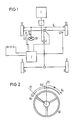
- FIG. 1 shows a schematic representation of a vehicle with all-wheel drive, in which a motor 1 drives the front wheels 51 and 52 via a manual transmission 2, a transfer case 3 and a controllable limited slip differential 4.
- the front wheels are moved via the steering 6 and the steering wheel 61.
- a speed sensor 53 is assigned to each of the front wheels and detects the wheel speed.
- a steering angle sensor 62 is located on the steering wheel 61 and detects the direction and amount of the movements of the steering wheel.
- the signals supplied by the speed sensors 53 and the rotation angle sensor 62 are processed in a control unit 7.
- the rear wheels 8 are also driven from the transfer case 3.
- the method according to the invention can also be used in vehicles with pure front-wheel drive.
- the method described here provides that the control unit 7 determines when one of the drive wheels 51, 52 is spinning; it evaluates the signals supplied by the speed sensors 53.
- the ratio of the signals supplied by the two sensors 53 serves as a criterion as to whether one of the drive wheels 51, 52 is spinning. A certain difference is allowed to allow normal cornering. If this difference exceeds a certain amount, the differential lock 4 is actuated.
- the invention makes use of the knowledge that the steering 6 of the vehicle is moved in the direction of the vehicle side by the occurrence of different peripheral forces, on which the lower peripheral forces act on the drive wheel 51, 52. If, due to the road condition, the drive wheel 51 has poor grip and spins, but the other drive wheel 52 has good grip, and then the differential lock 4 is switched on, it can be expected that a disturbing torque occurs in the direction of the drive wheel 51 at the steering 6.
- the control unit 7 uses the values supplied by the rotation angle sensor 62 to determine whether the steering wheel 61 is moving in the direction of the side of the vehicle on which the spinning drive wheel 51 is located. In the following, this direction is called the Rn direction (low friction coefficient direction). The other direction is called the Rh direction in the following (coefficient of friction-high direction). If the steering wheel 61 moves in the Rn direction, it is assumed that different coefficients of friction between the road surface and the drive wheels 51, 52 act on the steering 6. Thereupon, the degree of locking of the differential lock 4 is reduced until the steering wheel is moved again in the Rh direction, from which it is concluded that either the moment on the steering wheel no longer acts or the driver actively countersteers.
- FIG. 1 A development of the method is illustrated by FIG. At the beginning of the automatic actuation of the differential lock 4, the starting position PO of the steering wheel 61 is stored.
- Steering angles that occur in the Rh direction are evaluated as counter-steering by the driver on the disturbance torque. This does not affect the regulation of the degree of locking.
- the steering wheel 61 is in a new position P1. Steering angles that occur from this new position in the Rn1 direction are regarded as corrections by the driver when counter-steering as long as the steering wheel 61 has not yet reached its starting position PO. Only when the steering wheel Moving beyond the position PO in the Rn direction, the degree of locking is reduced.
- the control unit acts on the brake of the spinning wheel.
- the control unit uses a rotation angle sensor attached to the steering wheel to determine whether the steering wheel is moving in the direction of the side of the vehicle on which the spinning drive wheel is located (Rn direction). If the steering wheel moves in the Rn direction, the braking intervention is reduced. At the beginning of the brake intervention, the starting position PO of the steering wheel is saved. Analogous to the use of a regulated differential lock, steering locks that are attributable to the driver's counter-steering are recognized and do not influence the use of the vehicle brake.
Landscapes
- Engineering & Computer Science (AREA)
- Transportation (AREA)
- Mechanical Engineering (AREA)
- Chemical & Material Sciences (AREA)
- Combustion & Propulsion (AREA)
- Retarders (AREA)
- Arrangement And Driving Of Transmission Devices (AREA)
Priority Applications (2)
| Application Number | Priority Date | Filing Date | Title |
|---|---|---|---|
| EP19900109816 EP0457945B1 (fr) | 1990-05-23 | 1990-05-23 | Méthode de contrôle du taux de plissement d'un différentiel commandable pour véhicules avec train avant motrice |
| DE90109816T DE59002758D1 (de) | 1990-05-23 | 1990-05-23 | Verfahren zum Regeln des Sperrgrades eines Sperrdifferentials bei Fahrzeugen mit angetriebener Vorderachse. |
Applications Claiming Priority (1)
| Application Number | Priority Date | Filing Date | Title |
|---|---|---|---|
| EP19900109816 EP0457945B1 (fr) | 1990-05-23 | 1990-05-23 | Méthode de contrôle du taux de plissement d'un différentiel commandable pour véhicules avec train avant motrice |
Publications (2)
| Publication Number | Publication Date |
|---|---|
| EP0457945A1 true EP0457945A1 (fr) | 1991-11-27 |
| EP0457945B1 EP0457945B1 (fr) | 1993-09-15 |
Family
ID=8204017
Family Applications (1)
| Application Number | Title | Priority Date | Filing Date |
|---|---|---|---|
| EP19900109816 Expired - Lifetime EP0457945B1 (fr) | 1990-05-23 | 1990-05-23 | Méthode de contrôle du taux de plissement d'un différentiel commandable pour véhicules avec train avant motrice |
Country Status (2)
| Country | Link |
|---|---|
| EP (1) | EP0457945B1 (fr) |
| DE (1) | DE59002758D1 (fr) |
Cited By (1)
| Publication number | Priority date | Publication date | Assignee | Title |
|---|---|---|---|---|
| US6386308B1 (en) * | 1997-02-06 | 2002-05-14 | Toyota Jidosha Kabushiki Kaisha | Apparatus for controlling drive forces of vehicle drive wheels connected by differential, by braking drive wheel having smaller critical drive force |
Citations (4)
| Publication number | Priority date | Publication date | Assignee | Title |
|---|---|---|---|---|
| FR2434969A1 (fr) * | 1978-08-30 | 1980-03-28 | Bardot Michel | Differentiel a glissement auto-controle |
| DE3440492A1 (de) * | 1984-11-06 | 1986-05-07 | Xaver Fendt & Co, 8952 Marktoberdorf | Verfahren und einrichtung zum automatischen vermindern des relativschlupfes eines achswellenpaares eines kraftfahrzeuges |
| EP0311139A2 (fr) * | 1987-10-09 | 1989-04-12 | Nissan Motor Co., Ltd. | Système de commande de force limitative d'un differentiel, répondant à la vitesse de véhicule et à l'angle de braquage |
| FR2638401A1 (fr) * | 1988-10-28 | 1990-05-04 | Peugeot | Procede et dispositif de pilotage d'un differentiel commande notamment pour vehicule automobile |
-
1990
- 1990-05-23 EP EP19900109816 patent/EP0457945B1/fr not_active Expired - Lifetime
- 1990-05-23 DE DE90109816T patent/DE59002758D1/de not_active Expired - Lifetime
Patent Citations (4)
| Publication number | Priority date | Publication date | Assignee | Title |
|---|---|---|---|---|
| FR2434969A1 (fr) * | 1978-08-30 | 1980-03-28 | Bardot Michel | Differentiel a glissement auto-controle |
| DE3440492A1 (de) * | 1984-11-06 | 1986-05-07 | Xaver Fendt & Co, 8952 Marktoberdorf | Verfahren und einrichtung zum automatischen vermindern des relativschlupfes eines achswellenpaares eines kraftfahrzeuges |
| EP0311139A2 (fr) * | 1987-10-09 | 1989-04-12 | Nissan Motor Co., Ltd. | Système de commande de force limitative d'un differentiel, répondant à la vitesse de véhicule et à l'angle de braquage |
| FR2638401A1 (fr) * | 1988-10-28 | 1990-05-04 | Peugeot | Procede et dispositif de pilotage d'un differentiel commande notamment pour vehicule automobile |
Non-Patent Citations (1)
| Title |
|---|
| SOVIET INVENTIONS ILLUSTRATED Sektion Mechanik, Woche 8515, 22. Mai 1985, Zusammenfassung Nr. 91938/15, Derwent Publications Ltd., London, GB; & SU - A - 1115928 (BELORUSSIAN POLY) 30.09.1984 * |
Cited By (1)
| Publication number | Priority date | Publication date | Assignee | Title |
|---|---|---|---|---|
| US6386308B1 (en) * | 1997-02-06 | 2002-05-14 | Toyota Jidosha Kabushiki Kaisha | Apparatus for controlling drive forces of vehicle drive wheels connected by differential, by braking drive wheel having smaller critical drive force |
Also Published As
| Publication number | Publication date |
|---|---|
| EP0457945B1 (fr) | 1993-09-15 |
| DE59002758D1 (de) | 1993-10-21 |
Similar Documents
| Publication | Publication Date | Title |
|---|---|---|
| EP1016572B1 (fr) | Dispositif et procédé de stabilisation d'un attelage de véhicules constitué d'un tracteur et d'une remorque | |
| DE69935471T2 (de) | Gierwinkelregelverfahren für Kraftfahrzeuge | |
| DE69007132T2 (de) | Lenkvorrichtung für die Hinterräder eines Fahrzeuges. | |
| DE102008051530B4 (de) | Lenkregelungsvorrichtung für ein Fahrzeug | |
| WO2021083751A1 (fr) | Procédé de commande d'un véhicule automobile dans un mode de direction d'urgence au moyen d'une vectorisation de couple reposant sur un frein de roue avant | |
| DE3831105C1 (fr) | ||
| DE102018107612A1 (de) | Kraftfahrzeug mit Hinterradlenkung und Torque-Vectoring auf der Hinterradachse | |
| DE102008045078A1 (de) | Steuerungssystem für ein Fahrzeug | |
| DE3939069A1 (de) | Kraftfahrzeug | |
| EP1045783B1 (fr) | Dispositif et procede pour limiter la vitesse de roulement en arriere d'un vehicule automobile | |
| DE2818813C2 (fr) | ||
| DE102007007442A1 (de) | Verfahren zur reibwertabhängigen Veränderung des Lenkmoments und Lenksystem zur Durchführung des Verfahrens | |
| DE102004042188B4 (de) | Fahrzeugbewegungssteuergerät | |
| DE19723841B4 (de) | Kraftfahrzeug und Verfahren zum Betreiben eines Kraftfahrzeuges mit einer Vorrichtung zur Bekämpfung von Schleuderbewegungen | |
| DE102017124317A1 (de) | Verfahren zur Bestimmung eines Reibungskoeffizienten zwischen einem Rad eines Kraftfahrzeuges und einer Straßenoberfläche mit Torque Vectoring | |
| DE102021212197B3 (de) | Steer-by-wire-Lenksystem und Verfahren zum Betreiben eines steer-by-wire-Lenksystems | |
| EP1799484B1 (fr) | Procede et dispositif pour regler le degre de verrouillage d'un systeme de verrouillage de differentiel a commande electronique | |
| DE19954131B4 (de) | Verfahren zum Reduzieren eines Radschlupfs eines Kraftfahrzeugs | |
| DE19618624C1 (de) | Vorrichtung zur Auswertung von Signalen | |
| EP4126616A1 (fr) | Procédé et véhicule automobile | |
| DE102016010849A1 (de) | Stellteil und Steuerung für ein Kraftfahrzeug | |
| EP0457945B1 (fr) | Méthode de contrôle du taux de plissement d'un différentiel commandable pour véhicules avec train avant motrice | |
| EP1661750B1 (fr) | Procédé et dispositif de régularisation de la vitesse d'un véhicule | |
| EP0511473A2 (fr) | Système de régulation du glissement à l'entraînement | |
| DE19909453A1 (de) | Verfahren und Regelsystem zur Verbesserung des Fahrverhalten eines Fahrzeugs beim Durchfahren einer Kurvenbahn |
Legal Events
| Date | Code | Title | Description |
|---|---|---|---|
| PUAI | Public reference made under article 153(3) epc to a published international application that has entered the european phase |
Free format text: ORIGINAL CODE: 0009012 |
|
| 17P | Request for examination filed |
Effective date: 19901205 |
|
| AK | Designated contracting states |
Kind code of ref document: A1 Designated state(s): AT BE CH DE DK ES FR GB GR IT LI LU NL SE |
|
| RBV | Designated contracting states (corrected) |
Designated state(s): DE FR GB IT |
|
| 17Q | First examination report despatched |
Effective date: 19930218 |
|
| GRAA | (expected) grant |
Free format text: ORIGINAL CODE: 0009210 |
|
| AK | Designated contracting states |
Kind code of ref document: B1 Designated state(s): DE FR GB IT |
|
| REF | Corresponds to: |
Ref document number: 59002758 Country of ref document: DE Date of ref document: 19931021 |
|
| ITF | It: translation for a ep patent filed | ||
| GBT | Gb: translation of ep patent filed (gb section 77(6)(a)/1977) |
Effective date: 19931122 |
|
| ET | Fr: translation filed | ||
| PLBE | No opposition filed within time limit |
Free format text: ORIGINAL CODE: 0009261 |
|
| STAA | Information on the status of an ep patent application or granted ep patent |
Free format text: STATUS: NO OPPOSITION FILED WITHIN TIME LIMIT |
|
| 26N | No opposition filed | ||
| REG | Reference to a national code |
Ref country code: GB Ref legal event code: IF02 |
|
| PG25 | Lapsed in a contracting state [announced via postgrant information from national office to epo] |
Ref country code: IT Free format text: LAPSE BECAUSE OF NON-PAYMENT OF DUE FEES;WARNING: LAPSES OF ITALIAN PATENTS WITH EFFECTIVE DATE BEFORE 2007 MAY HAVE OCCURRED AT ANY TIME BEFORE 2007. THE CORRECT EFFECTIVE DATE MAY BE DIFFERENT FROM THE ONE RECORDED. Effective date: 20050523 |
|
| PGFP | Annual fee paid to national office [announced via postgrant information from national office to epo] |
Ref country code: GB Payment date: 20080522 Year of fee payment: 19 |
|
| PGFP | Annual fee paid to national office [announced via postgrant information from national office to epo] |
Ref country code: DE Payment date: 20090531 Year of fee payment: 20 |
|
| GBPC | Gb: european patent ceased through non-payment of renewal fee |
Effective date: 20090523 |
|
| REG | Reference to a national code |
Ref country code: FR Ref legal event code: ST Effective date: 20100129 |
|
| PG25 | Lapsed in a contracting state [announced via postgrant information from national office to epo] |
Ref country code: FR Free format text: LAPSE BECAUSE OF NON-PAYMENT OF DUE FEES Effective date: 20090602 |
|
| PGFP | Annual fee paid to national office [announced via postgrant information from national office to epo] |
Ref country code: FR Payment date: 20080526 Year of fee payment: 19 |
|
| PG25 | Lapsed in a contracting state [announced via postgrant information from national office to epo] |
Ref country code: GB Free format text: LAPSE BECAUSE OF NON-PAYMENT OF DUE FEES Effective date: 20090523 |
|
| PG25 | Lapsed in a contracting state [announced via postgrant information from national office to epo] |
Ref country code: DE Free format text: LAPSE BECAUSE OF EXPIRATION OF PROTECTION Effective date: 20100523 |