EP0311139A2 - Système de commande de force limitative d'un differentiel, répondant à la vitesse de véhicule et à l'angle de braquage - Google Patents
Système de commande de force limitative d'un differentiel, répondant à la vitesse de véhicule et à l'angle de braquage Download PDFInfo
- Publication number
- EP0311139A2 EP0311139A2 EP88116790A EP88116790A EP0311139A2 EP 0311139 A2 EP0311139 A2 EP 0311139A2 EP 88116790 A EP88116790 A EP 88116790A EP 88116790 A EP88116790 A EP 88116790A EP 0311139 A2 EP0311139 A2 EP 0311139A2
- Authority
- EP
- European Patent Office
- Prior art keywords
- value
- vehicle speed
- steering
- predetermined
- equal
- Prior art date
- Legal status (The legal status is an assumption and is not a legal conclusion. Google has not performed a legal analysis and makes no representation as to the accuracy of the status listed.)
- Granted
Links
- 230000000670 limiting effect Effects 0.000 title claims abstract description 62
- 230000003247 decreasing effect Effects 0.000 claims abstract description 8
- 230000007246 mechanism Effects 0.000 claims description 26
- 230000007423 decrease Effects 0.000 claims description 13
- 239000012530 fluid Substances 0.000 claims description 3
- 230000009699 differential effect Effects 0.000 claims description 2
- 230000006870 function Effects 0.000 description 11
- 230000004044 response Effects 0.000 description 11
- 230000007935 neutral effect Effects 0.000 description 10
- 230000036316 preload Effects 0.000 description 8
- 230000008859 change Effects 0.000 description 6
- 230000005540 biological transmission Effects 0.000 description 4
- 238000010586 diagram Methods 0.000 description 3
- 238000000034 method Methods 0.000 description 3
- 230000008569 process Effects 0.000 description 3
- 238000006073 displacement reaction Methods 0.000 description 2
- 230000001133 acceleration Effects 0.000 description 1
- 230000000694 effects Effects 0.000 description 1
- 238000005096 rolling process Methods 0.000 description 1
- 230000003313 weakening effect Effects 0.000 description 1
Images







Classifications
-
- B—PERFORMING OPERATIONS; TRANSPORTING
- B60—VEHICLES IN GENERAL
- B60K—ARRANGEMENT OR MOUNTING OF PROPULSION UNITS OR OF TRANSMISSIONS IN VEHICLES; ARRANGEMENT OR MOUNTING OF PLURAL DIVERSE PRIME-MOVERS IN VEHICLES; AUXILIARY DRIVES FOR VEHICLES; INSTRUMENTATION OR DASHBOARDS FOR VEHICLES; ARRANGEMENTS IN CONNECTION WITH COOLING, AIR INTAKE, GAS EXHAUST OR FUEL SUPPLY OF PROPULSION UNITS IN VEHICLES
- B60K23/00—Arrangement or mounting of control devices for vehicle transmissions, or parts thereof, not otherwise provided for
- B60K23/04—Arrangement or mounting of control devices for vehicle transmissions, or parts thereof, not otherwise provided for for differential gearing
-
- Y—GENERAL TAGGING OF NEW TECHNOLOGICAL DEVELOPMENTS; GENERAL TAGGING OF CROSS-SECTIONAL TECHNOLOGIES SPANNING OVER SEVERAL SECTIONS OF THE IPC; TECHNICAL SUBJECTS COVERED BY FORMER USPC CROSS-REFERENCE ART COLLECTIONS [XRACs] AND DIGESTS
- Y10—TECHNICAL SUBJECTS COVERED BY FORMER USPC
- Y10T—TECHNICAL SUBJECTS COVERED BY FORMER US CLASSIFICATION
- Y10T74/00—Machine element or mechanism
- Y10T74/19—Gearing
- Y10T74/19172—Reversal of direction of power flow changes power transmission to alternate path
-
- Y—GENERAL TAGGING OF NEW TECHNOLOGICAL DEVELOPMENTS; GENERAL TAGGING OF CROSS-SECTIONAL TECHNOLOGIES SPANNING OVER SEVERAL SECTIONS OF THE IPC; TECHNICAL SUBJECTS COVERED BY FORMER USPC CROSS-REFERENCE ART COLLECTIONS [XRACs] AND DIGESTS
- Y10—TECHNICAL SUBJECTS COVERED BY FORMER USPC
- Y10T—TECHNICAL SUBJECTS COVERED BY FORMER US CLASSIFICATION
- Y10T74/00—Machine element or mechanism
- Y10T74/19—Gearing
- Y10T74/19172—Reversal of direction of power flow changes power transmission to alternate path
- Y10T74/19177—Input and output exchange functions
Definitions
- the present invention relates to a differential limiting (or slip limiting) system capable of actively controlling a differential limiting action to a rotational speed difference between left and right drive wheels in accordance with a control signal.
- This conventional control system includes a vehicle speed sensing means, and a controlling means for controlling a fluid pressure in accordance with the vehicle speed, and is arranged to control an engagement force (that is, a differential limiting force) of a friction clutch disposed between a differential case of a side gear by controlling the fluid pressure supplied to the friction clutch.
- this conventional control system is arranged to increase the engagement force of the friction clutch when the vehicle speed becomes higher, and to decrease the clutch engagement force when the vehicle speed becomes lower. Therefore, when the driver changes the course of the vehicle from one lane to another at high vehicle speeds, an undermoment due to the differential limiting action is produced at the start of the turning operation of the steering wheel, so that the vehicle response is degraded. As shown in Fig. 14, the undermoment is produced when the direction M′ of a moment due to the differential limiting action is opposite to a turning direction M of the vehicle. As shown in Fig. 15, an overmoment is produced when both directions M and M′ are the same.
- an object of the present invention to provide a differential limiting force control system which can prevent an undesired decrease of the vehicle response by controlling the differential limiting force in accordance with the vehicle speed, and simultaneously by decreasing the differential limiting force when a steering angle is smaller than a predetermined angle, or when a steering angular speed is higher than a predetermined angular speed value.
- a differential limiting force control system comprises a differential mechanism, vehicle speed sensing means, steering condition sensing means, command value determining means, controlling means, and adjusting means.
- the differential mechanism is provided between left and right drive wheels of the vehicle, and comprises means for limiting a differential action in accordance with a control signal.
- the vehicle sensing means senses a vehicle speed of the vehicle, and produces a first signal representing the vehicle speed.
- the steering condition sensing means senses a steering condition of the vehicle, and produces a second signal representing the steering condition.
- the determining means determines a command value in accordance with the first signal.
- the controlling means produces the control signal in accordance with the command value.
- the adjusting means decreases the command value when the second signal is in a predetermined condition.
- the adjusting means is arranged to decrease the command value when a steering angle is equal to or smaller than a predetermined angle, or when a steering angular speed is equal to or higher than a predetermined angular speed.
- the controlling means makes the differential limiting force equal to a value corresponding to the command value.
- the controlling means controls the differential limiting force so that the differential limiting force is proportional to the command value.
- the control system decreases the undermoment due to the differential limiting action, and improve the response of the vehicle by decreasing the differential limiting force when the steering wheel angle is smaller than the predetermined angle, or when the steering angular speed is higher than the predetermined angular speed.
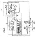
- FIG. 2-7 A first embodiment of the present invention is shown in Figs. 2-7.
- a vehicle has front wheels 10FL and 10FR, rear wheels 10RL and 10RR, a rear wheel drive axle 12, a limited slip differential 14 disposed in the rear wheel drive axle 12, a propeller shaft 15, a steering shaft 16, an oil pressure source 18 for supplying an oil pressure to a differential limitingdevice of the limited slip differential 14, and a controller 20 for controlling the oil pressure of the pressure source 18.
- Fig. 3 shows the differential 14.
- a U.S. Patent 4,679,463 discloses a differential of the same type. The disclosure of this patent is herein incorporated by reference.
- the differential 14 has a differential mechanism 38 enclosed in a housing 36.
- a differential gear case 44 is rotatably supported by bearings 42 and 43 in the housing 36.
- a final gear 45 is fixed to the differential gear case 44.
- the final gear 45 is in engagement with a drive pinion gear 46 mounted on the rear end of the propeller shaft 15.
- Pinion gears 48 are rotatably supported by a pinion mate shaft 47 to the differential gear case 44.
- the pinion gears 48 are in engagement with left and right side gears 49L and 49R.
- the left side gear 49L is splined to an inner end of a left drive axle shaft of the axle 12, whose outer end is conected with the rear left drive wheel 10RL.
- the right side gear 49R is connected to the rear right drive wheel 10RR by a right drive axle shaft in the same manner.
- a differential limiting (or slip limiting) mechanism 50 is provided in the differential gear case 44.
- the differential limiting mechanism 50 has left and right pressure rings 51L and 51R, which are rotatably mounted on the side gears 49L and 49R, respectively, and which have wedge-shaped notches receiving the pinion mate shaft 47.
- the differential limiting mechanism 50 further includes left and right friction clutches 52L and 52R provided beteween the differential gear case 44 and the side gears 49L, 49R, left and right pressure levers 53L and 53R for providing preload to the friction clutches 52L and 52R, and left and right cylinder portions 55L and 55R for moving the pressure levers 53L and 53R back and forth through bearings 54L and 54R, respectively.
- the left cylinder portion 55L is formed in a left end of the housing 36, and has a piston 57 which is connected with the pressure lever 53L through a piston rod 58 passing through the housing 36.
- the pressure source 18 has an oil pressure pump 62 driven by a motor 60.
- the motor 60 is controlled by the controller 20.
- An inlet side of the pump 62 is connected with a reservoir tank 61.
- An outlet side of the pump 62 is connected to the cylinder portions 55L and 55R of the differential limiting mechanism 50 through a check valve 63 and an orifice 64.
- a relief valve 65 is provided so that an upper limit value of the outlet pressure of the pump 62 is set by the relief valve 65.
- An electromagnetic opening and closing valve 66 controlled by the controller 20 is disposed in parallel to the pump 62 and the check valve 63.
- the controller 20 By closing the electromagnetic valve 66, the controller 20 applies the output oil pressure of the pump 62 to the cylinder portions 55L and 55R of the differential limiting mechanism 50, and thereby puts the differential limiting mechanism 50 to an operative state.
- the controller 20 By opening the electromagnetic valve 66, the controller 20 shuts off the supply of the outlet pressure of the pump 62 to the differential limiting mechanism 50, and puts the differential limiting mechanism 50 into an inoperative state.
- a pressure switch 67 for producing an output signal of a logical value "1" at a predetermined preset pressure.
- a steering angle sensor 70 is provided in the steering shaft 16.
- the steering angle sensor 70 produces a steering angle signal ⁇ of a positive analog voltage, representing a steering wheel angle. As shown in Fig. 4, the steering angle ⁇ is zero when the steering wheel is in the neutral position. As the steering wheel is turned leftwardly or rightwardly away from the neutral position, the steering angle ⁇ increases linearly.
- the steering angle signal ⁇ is sent to the controller 20.
- a vehicle speed sensor 71 is disposed at a predetermined position of the vehicle body.
- the vehicle speed sensor 71 of this embodiment is arranged to optically detect a rotational speed on the output side of the transmission of the vehicle.
- the vehicle speed sensor 71 produces a vehicle speed pulse signal v corresponding to a vehicle speed V, and sends this vehicle speed signal to the controller 20.
- the controller 20 includes a command value determining section 74, a command value adjusting section 75, and an oil pressure controlling section 76 for controlling the output pressure of the oil pressure source 18 in accordance with a command value T determined by the command value determining section 74.
- the final command value T is sent to the oil pressure controlling section 76.
- the command value adjusting section 75 includes a differentiating circuit 83 for determining a steering angular signal ⁇ by differentiating the steering angle signal ⁇ of the steering angle sensor 70, an absolute value circuit 29 for determining the absolute value of the derivative ⁇ of the sdteering angle ⁇ , and a second function generator 85 producing the second command value T2 corresponding to the absolute value
- the first function generator 81 has a characteristic shown in Fig. 5.
- a predetermined first speed value V1 (30 kem/h, for example)
- the first command value T1 is held equal to zero.
- the vehicle speed V increases from the first speed value V1 to a second predetermined speed value V2 (50 km/h, for example)
- the first command value T1 increases linearly from zero to a limit value.
- the vehicle speed V is higher than the second speed value V2
- the first command value T1 is held equal to the constant limit value.
- the second function generator 85 has a characteristic shown in Fig. 6.
- the second command value T2 rieses abruptly like a step change when the absolute value of the steering angular speed ⁇ exceeds a predetermined angular speed value ⁇ 1 (45 deg/sec, for example).
- the second command value T2 is held equal to zero when the absolute value of the time rate of change of the steering angle ⁇ is lower than the predetermined angular speed value ⁇ 1.
- the second command value T2 is held equal to a predetermined constant value when the absolute value of the rate of change of the steering angle ⁇ is higher than the predetermined angular speed value ⁇ 1.
- the pressure controlling section 76 is composed of a microcomputer including an interface circuit, a processing unit, and a memory section having RAM and ROM.
- the pressure controlling section 76 receives the final command value T from the command value determining section 74, and controls the motor 60 and the electromagnetic valve 66 to control the differential limiting force of the differential limiting mechanism 50 in accordance with the final command value T.
- the pressure controlling section 76 drives the motor 60 at a controlled duty ratio by using a switch signal of the pressure switch 67 as a feedback signal so as to obtain the differential limiting force commanded by the final command value T, and provides the preload of a predetermined pressure, that is the differential limiting force, to the friction clutches 52L and 52R of the differential limiting mechanism 50.
- the pressure controlling section 76 of the controller 20 controls the differential limiting force of the differential limiting mechanism 50 in accordance with the final command value T.
- the pressure controlling section 76 puts the electromagnetic valve 66 in its open position, and causes the outlet pressure of the pump 62 to return to the reservoir tank 61. Therefore, the preload to the friction clutches 52L and 52R is cancelled, and the differential limiting force is removed.
- the differential mechanism 36 transmits the rotational driving force from the transmission to the drive wheels 10RL and 10RR through the drive axle 12.
- the driving force (or torque) transmitted from the transmission through the propeller shaft 15 is further transmitted to the differential gear case 44 through the drive pinion gear 46 and the final gear 45, and then to the side gears 49L and 49R through the pinion mate shaft 47 and the pinions 48. Finally, the driving force is transmitted from the side gears 49L and 49R to the drive wheels 10RL and 10RR through the drive axle 12.
- the pressure controlling section 76 performs the duty factor control of the motor 60, and supplies the oil pressure corresponding to the final command value T to the cylinder portions 55L and 55R of the differential limiting mechanism 50 to apply the preload to the friction clutches 52L and 52R.
- the pressure controlling section 76 provides no preload to the friction clutches 52L and 52R. In either case, the differential gear case 44, and the side gears 49L and 49R rotate at the same speed because the vehicle is moving straight ahead. Therefore, the pressure rings 51L and 51R are not pushed outwardly by the pinion mate shaft 47, and the differential limiting mechanism 50 remains in the inoperative state.
- the first function generator 81 determines the first command value T1 in accordance with the vehicle speed V, and simultaneously the steering angle signal ⁇ representing the angular displacement of the steering wheel is sent from the steering angle sensor 70 to the command adjusting section 75.
- the second function generator 85 of the command value adjusting section 75 determines the second command value T2 corresponding to the absolute value
- of the angular speed of the steering wheel. In this condition, the second command value T2 is zero because of the low angular speed of the steering wheel, and the final command value T is equal to the first command value T1 (T T1).
- the control system decreases the preload provided to the differential limiting mechanism 50, i.e. the differential limiting force, by the amount equal to T2, and decreases the undermoment due to the differential limiting force, so that the control system can improve the controllability of the vehicle by preventing a decrease of the steering response characteristic.
- the second command value T2 becomes zero, and the control system ensures the satissfactory vehicle behavior by applying the differential limiting force.
- the final command value T determined by the adder 82 becomes equal to or lower than zero (T ⁇ 0).
- the preload produced by the pressure source 18 does not decreases below zero, and the differential limiting mechanism 50 is put in the inoperative state, so that only the differential mechanism 36 is in operation independently of the steering angular speed.
- the differential mechanism 36 absorbs the rotational speed difference between the drive wheels 10RL and 10RR by the rotation of the pinions 48, and the transmission torques of the left and right side gears 49L and 49R are equal to each other.
- the control system When the steering wheel is turned to the left from the neutral position, the control system is operated in the same manner, and improves the response of the vehicle especially when the angular speed of the steering weel is high.
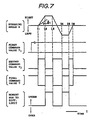
- Fig. 7 shows change in the final command value T determined by the control system of the first embodiment when the steering angle ⁇ is varied at the vehicle speed V higher than the second speed value V2 (V > V2).
- the upper limit value of the first command value T1 is set equal to the upper limit value of the second command value T2.
- is higher than the predetermined value ⁇ 1 between t1 and t2, between t3 and t4, and between t5 and t6.
- the second command value T2 is set equal to the upper value, and accordingly the moment due to the differential limiting action is held neutral to improve the response of the vehicle.
- the control system of this embodiment improves the response of the vehicle by decreasing the differential limiting force and weakening the undermoment at an initial stage of a rapid steering operation in which the steering angular speed is higher than the predetermined value, and the vehicle speed is higher than the predetermined value. Then, the control system prevents a decrease of the cornering performance by increasing the differential limiting force when the steering angular speed decreases below the predetermined value.
- a second embodiment of the present invention is shown in Figs. 8 and 9.
- a control system of the second embodiment is arranged to detect the steering condition by directly using the steering angle 0.
- the command value adjusting section 75 of the controller 20 is arranged as shown in Fig. 8.
- the control system of the second embodiment is difference from that of the first embodiment only in the command value adjusting section 75.
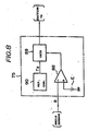
- the command value adjusting section 75 of the second embodiment has a comparator 88, a gate circuit 89 and a reference generator 90.
- the steering angle signal ⁇ of the steering angle sensor 70 is inputted to an inverting input terminal of the comparator 88.
- a noninverting input terminal of the comparator 88 is connected with a source of a reference voltage E corresponding to a predetermined reference steering angle value ⁇ 1.
- An output terminal of the comparator 88 is connected to a control terminal of the gate circuit 89. When the output of the comparator 88 is equal to the logical value "1", then the gate circuit 89 is in an open state.
- the gate circuit 89 When the output of the comparator 88 is equal to the logical value "0", then the gate circuit 89 is in a closed state. An input terminal of the gate circuit 89 is connected with the reference generator 90, which provides the second command value T2 which is a constant. When the gate circuit 89 is in the open state, the constant second command value T2 is allowed to pass through the gate circuit 89, and reaches the adder 82 of the command value determining section 74 shown in Fig. 2.
- the steering angle ⁇ is lower than the predetermined steering angle value ⁇ 1, in a period between t1 and t2, a period between t3 and t4, and a period between t5 and t6.
- the output signal of the comparator 88 is equal to the logical value "1”
- the gate circuit 89 is in the open state to allow the passage of the second command value T2. Therefore, the final command value T becomes equal to zero, and the moment due to the differential limiting action becomes neutral. In this way, the control system of the second embodiment also improves the vehicle response at an initial state of a steering operation.
- the control system of the second embodiment gives a preference to the response of the vehicle at an early state at which the steering angle is still small. After that, the control system brings the vehicle to a stable state by producing the undermoment.
- a third embodiment of the present invention is shown in Figs. 10-13.
- a control system of the third embodiment is arranged to detect the steering condition by using the steering angular speed as in the first embodiment.
- the controller 20 is entirely constituted by a micorcomputer, as shown in Fig. 10.
- a microcomputer 92 comprises an interface circuit 93, a processing unit 94, and a storage section 95.
- the pressure signal p, the vehicle speed signal v sent from the vehicle speed sensor 71, and the steering angle signal ⁇ sent from the steering angle sensor 70 through an A/D converter 96 are inputted into an input port side of the interface circuit 93.
- An output port side of the interface circuit 93 is connected thorugh a driver circuit 97 to the solenoid of the electromagnetic valve 66 shown in Fig. 2, and through a driver circuit 98 to the motor 60.
- the processing unit 94 reads the sensor signals p, v and ⁇ through the interface circuit 93, and processes the signals according to a predetermined program.
- the storage section 95 stores various data and programs.
- control system of the third embodiment is the same as that of the first embodiment.
- Figs. 11 and 12 are flowcharts of programs, which are preformed by the controller 20 of the third embodiment at intervals of a predetermined time length (20 msec, for example) as timer interrupt process.
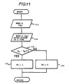
- the controller 20 determines whether the steering angle is increasing or not, by using the process of Fig. 11.
- the processing unit 94 reads a current value of the digitized steering angle signal ⁇ , and stores that value as ⁇ A .
- the processing unit 94 reads a new value of the digitized steering angle signal ⁇ after the elapse of a predetermined time length, and stores the new value as ⁇ B .
- the processing unit 94 determines whether a difference obtained by subtracting the first value ⁇ A from the second value ⁇ B is greater than zero ( ⁇ B - ⁇ A > 0), or not.
- the processing unit 94 proceeds to a step 114, at which the processing unit 94 sets a flag FS to "1" to indicate a condition that the steering wheel is being turned away from the straight ahead position, and the steering wheel angle is increasing.
- the processing unit 94 proceeds from the step 113 to a step 115, at which the processing unit 94 sets the flag FS to "0" to indicate that the steering angle is not increasing. After the step 114 or 115, the processing unit 94 returns to a main program.
- Fig. 12 shows a program for controlling the differential limiting force.
- the processing unit 94 reads the pressure signal p, the vehicle speed signal v and the steering angle signal ⁇ at a step 121, and determines the oil pressure P, the vehicle speed V and the steering angle ⁇ at a step 122. Then, the processing unit 94 determined the steering angular speed ⁇ , that is the time rate of change of the steering wheel angular displacement.
- the processing unit 94 determines the first command value T1 corresponding to the vehicle speed V by using a lookup table of functions values determined as shown in Fig. 5.
- the processing unit 94 determines the second command value T2 corresponding to the steering angular speed ⁇ by using a lookup table corresponding to Fig. 6.
- the processing unit 94 decreases the final command value T by T2 when the steering wheel is being turned away from the straight ahead position, and at the same time the steering angular speed is greater than the predetermined angular speed value ⁇ 1.
- the controller 20 makes the output pressure P of the pressure source 18, that is the differential limiting force, equal to a value corresponding to the final command value T, by delivering a motor drive signal and a valve switch signal to the motor 60 and the electromagnetic valve 66 through the driver circuits 97 and 98, respectively in accordance with the final command value T.
- the processing unit 94 proceeds from the step 126 or 127 to a step 130.
- the processing unit 94 makes the final command value T equal to the first command value T1 regardless of the second command value T2. Then, the processing unit 94 proceeds to the step 129.
- the final command value T is set equal to T1 when the steering wheel angle is not increasing, and when the steering wheel angle is increasing but the steering operation is slow.
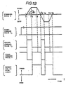
- Fig. 13 shows operations of the control system of the third embodiment.
- Fig. 13 is similar to Fig. 7 of the first embodiment, but different in the following point.
- the controller 20 of the third embodiment holds the second command value T2 equal to zero independently of the steering angular speed.
- the controller 20 of the third embodiment sets the second command value T2 equal to zero even if the steering angular speed is high.
- the control system of the third embodiment improves the response of the vehicle by putting the steering direction (toward the neutral position) and the understeer moment in phase.
- the vehicle speed sensor 71, and the steps 121 and 122 correspond to the vehicle speed sensing means
- the steering angle sensor 70 and the steps 121-123 correspond to the steering condition sensing means.
- the steps 124, 128 and 130 correspond to the command value determining means
- the steps 125-127 correspond to the command value adjusting means.
- an angular speed sensor for sensing the steering angular speed.
Landscapes
- Engineering & Computer Science (AREA)
- Chemical & Material Sciences (AREA)
- Combustion & Propulsion (AREA)
- Transportation (AREA)
- Mechanical Engineering (AREA)
- Arrangement And Mounting Of Devices That Control Transmission Of Motive Force (AREA)
Applications Claiming Priority (2)
| Application Number | Priority Date | Filing Date | Title |
|---|---|---|---|
| JP62255747A JPH0815851B2 (ja) | 1987-10-09 | 1987-10-09 | 差動制限装置 |
| JP255747/87 | 1987-10-09 |
Publications (3)
| Publication Number | Publication Date |
|---|---|
| EP0311139A2 true EP0311139A2 (fr) | 1989-04-12 |
| EP0311139A3 EP0311139A3 (en) | 1989-11-29 |
| EP0311139B1 EP0311139B1 (fr) | 1993-12-29 |
Family
ID=17283070
Family Applications (1)
| Application Number | Title | Priority Date | Filing Date |
|---|---|---|---|
| EP88116790A Expired - Lifetime EP0311139B1 (fr) | 1987-10-09 | 1988-10-10 | Système de commande de force limitative d'un differentiel, répondant à la vitesse de véhicule et à l'angle de braquage |
Country Status (4)
| Country | Link |
|---|---|
| US (1) | US5075854A (fr) |
| EP (1) | EP0311139B1 (fr) |
| JP (1) | JPH0815851B2 (fr) |
| DE (1) | DE3886652T2 (fr) |
Cited By (5)
| Publication number | Priority date | Publication date | Assignee | Title |
|---|---|---|---|---|
| EP0367962A1 (fr) * | 1988-11-08 | 1990-05-16 | Gkn Automotive Aktiengesellschaft | Procédé et dispositif de contrôle du verouillage d'un différentiel |
| EP0457945A1 (fr) * | 1990-05-23 | 1991-11-27 | Siemens Aktiengesellschaft | Méthode de contrôle du taux de plissement d'un différentiel commandable pour véhicules avec train avant motrice |
| EP0592990A1 (fr) * | 1992-10-12 | 1994-04-20 | Honda Giken Kogyo Kabushiki Kaisha | Système de contrôle du couple pour les roues motrices d'un véhicule automobile |
| US5484033A (en) * | 1990-07-07 | 1996-01-16 | Gkn Automotive Ag | Drive assembly |
| EP0841206A3 (fr) * | 1996-11-07 | 1999-07-07 | Honda Giken Kogyo Kabushiki Kaisha | Système de répartition du couple avec embrayages hydrauliques |
Families Citing this family (14)
| Publication number | Priority date | Publication date | Assignee | Title |
|---|---|---|---|---|
| JP2639173B2 (ja) * | 1990-04-20 | 1997-08-06 | 日産自動車株式会社 | 車両用差動制限制御装置 |
| JP2600986B2 (ja) * | 1990-07-06 | 1997-04-16 | 三菱自動車工業株式会社 | 後輪の操舵制御方法 |
| JPH0558188A (ja) * | 1991-08-27 | 1993-03-09 | Mitsubishi Electric Corp | リアデフアレンシヤルロツク制御装置 |
| CA2077461C (fr) * | 1992-08-28 | 2000-02-15 | Jerry L. Nadler | Inhibition de la formation ou de l'activite de la voie de la leucocyte 12-lipoxydase humaine |
| JPH06247177A (ja) * | 1993-02-26 | 1994-09-06 | Mazda Motor Corp | 車両の差動制限装置 |
| JP3301183B2 (ja) * | 1993-11-24 | 2002-07-15 | 日産自動車株式会社 | 車両の前後輪間駆動力配分制御装置 |
| JP4754053B2 (ja) * | 2000-09-14 | 2011-08-24 | 富士重工業株式会社 | 四輪駆動車の動力分配装置 |
| US6810318B2 (en) * | 2002-09-13 | 2004-10-26 | General Motors Corporation | Drive torque transfer scheme |
| US7264078B2 (en) * | 2005-02-10 | 2007-09-04 | Deere & Company | Calibration method for inter-axle differential control system |
| JP4626550B2 (ja) * | 2006-03-24 | 2011-02-09 | 三菱自動車工業株式会社 | 車両の旋回挙動制御装置 |
| JP4826308B2 (ja) * | 2006-03-24 | 2011-11-30 | 三菱自動車工業株式会社 | 車両の旋回挙動制御装置 |
| AT511442B1 (de) | 2011-10-10 | 2012-12-15 | Wilhelm Ing Oberaigner | Ausgleichsgetriebe |
| JP7606830B2 (ja) * | 2020-07-29 | 2024-12-26 | 株式会社小松製作所 | 無人車両の制御システム、無人車両、及び無人車両の制御方法 |
| CN117601670B (zh) * | 2023-12-27 | 2024-10-22 | 苏州行至动力技术有限公司 | 一种汽车轮毂电机差速控制系统及方法 |
Family Cites Families (25)
| Publication number | Priority date | Publication date | Assignee | Title |
|---|---|---|---|---|
| US4012968A (en) * | 1974-12-23 | 1977-03-22 | Borg-Warner Corporation | Speed-sensitive differential mechanism |
| SU797921A1 (ru) * | 1979-04-03 | 1981-01-23 | Белорусский Ордена Трудового Крас-Ного Знамени Политехнический Ин-Ститут | Устройство дл автоматической бло-КиРОВКи диффЕРЕНциАлА ТРАНСпОРТ-НОгО СРЕдСТВА |
| JPS5715019A (en) * | 1980-06-27 | 1982-01-26 | Fuji Heavy Ind Ltd | Changeover device for 2, 4 wheel drive in 4-wheel drive vehicle |
| JPS588434A (ja) * | 1981-07-07 | 1983-01-18 | Fuji Heavy Ind Ltd | 4輪駆動車の切換制御装置 |
| JPS59206228A (ja) * | 1983-05-09 | 1984-11-22 | Nissan Motor Co Ltd | 4輪駆動車 |
| US4549448A (en) * | 1983-06-13 | 1985-10-29 | Deere & Company | Differential lock control system responsive to a plurality of vehicle parameters |
| JPS6053430A (ja) * | 1983-08-31 | 1985-03-27 | Kubota Ltd | 車両のデファレンシャルロック装置 |
| JPS60255575A (ja) * | 1984-05-09 | 1985-12-17 | Koyo Seiko Co Ltd | 操舵角センサの信号処理方法 |
| US4679463A (en) * | 1984-08-31 | 1987-07-14 | Nissan Motor Co., Ltd. | Limited slip differential |
| JPS6167629A (ja) * | 1984-09-07 | 1986-04-07 | Nissan Motor Co Ltd | 差動制限装置 |
| JPS61102320A (ja) * | 1984-10-23 | 1986-05-21 | Nissan Motor Co Ltd | 車両の差動制御装置 |
| JPS61132420A (ja) * | 1984-11-30 | 1986-06-19 | Hino Motors Ltd | 自動車の走行安定装置 |
| JPS61157437A (ja) * | 1984-12-28 | 1986-07-17 | Nissan Motor Co Ltd | 4輪駆動車の駆動力配分制御装置 |
| JPS61169326A (ja) * | 1985-01-21 | 1986-07-31 | Nissan Motor Co Ltd | 4輪駆動車の駆動力配分制御装置 |
| JPS61178233A (ja) * | 1985-02-05 | 1986-08-09 | Nissan Motor Co Ltd | 4輪駆動車の差動制限制御装置 |
| JPS62103226A (ja) * | 1985-10-31 | 1987-05-13 | Nissan Motor Co Ltd | 車両用差動制限制御装置 |
| JPS62103227A (ja) * | 1985-10-31 | 1987-05-13 | Nissan Motor Co Ltd | 車両用差動制限制御装置 |
| DE3545717A1 (de) * | 1985-12-21 | 1987-06-25 | Daimler Benz Ag | Einrichtung zur vortriebsregelung an kraftfahrzeugen |
| US4699236A (en) * | 1986-01-20 | 1987-10-13 | Toyota Jidosha Kabushiki Kaisha | Four wheel drive vehicle slippage control device and method limiting center differential action during transmission shifting |
| EP0236694B1 (fr) * | 1986-03-11 | 1990-11-28 | Dr.Ing.h.c. F. Porsche Aktiengesellschaft | Dispositif de commande de la transmission d'un véhicule à quatre roues motrices |
| JPS62214019A (ja) * | 1986-03-13 | 1987-09-19 | Nissan Motor Co Ltd | 駆動輪推進制御装置付車両の差動制限制御装置 |
| EP0247820B1 (fr) * | 1986-05-26 | 1992-08-05 | Toyota Jidosha Kabushiki Kaisha | Transmission différentielle |
| US4813297A (en) * | 1986-05-26 | 1989-03-21 | Toyota Jidosha Kabushiki Kaisha | Differential gear |
| JPH0818502B2 (ja) * | 1986-06-30 | 1996-02-28 | アイシン・エィ・ダブリュ株式会社 | 前後輪係合機構を備えた4輪駆動車 |
| US4779696A (en) * | 1986-07-24 | 1988-10-25 | Mazda Motor Corporation | Vehicle slip control apparatus |
-
1987
- 1987-10-09 JP JP62255747A patent/JPH0815851B2/ja not_active Expired - Lifetime
-
1988
- 1988-10-10 DE DE88116790T patent/DE3886652T2/de not_active Expired - Fee Related
- 1988-10-10 EP EP88116790A patent/EP0311139B1/fr not_active Expired - Lifetime
-
1990
- 1990-08-09 US US07/565,207 patent/US5075854A/en not_active Expired - Fee Related
Cited By (6)
| Publication number | Priority date | Publication date | Assignee | Title |
|---|---|---|---|---|
| EP0367962A1 (fr) * | 1988-11-08 | 1990-05-16 | Gkn Automotive Aktiengesellschaft | Procédé et dispositif de contrôle du verouillage d'un différentiel |
| US5071392A (en) * | 1988-11-08 | 1991-12-10 | Gkn Automotive Ag | Process and device for controlling locking differentials |
| EP0457945A1 (fr) * | 1990-05-23 | 1991-11-27 | Siemens Aktiengesellschaft | Méthode de contrôle du taux de plissement d'un différentiel commandable pour véhicules avec train avant motrice |
| US5484033A (en) * | 1990-07-07 | 1996-01-16 | Gkn Automotive Ag | Drive assembly |
| EP0592990A1 (fr) * | 1992-10-12 | 1994-04-20 | Honda Giken Kogyo Kabushiki Kaisha | Système de contrôle du couple pour les roues motrices d'un véhicule automobile |
| EP0841206A3 (fr) * | 1996-11-07 | 1999-07-07 | Honda Giken Kogyo Kabushiki Kaisha | Système de répartition du couple avec embrayages hydrauliques |
Also Published As
| Publication number | Publication date |
|---|---|
| EP0311139B1 (fr) | 1993-12-29 |
| JPH0815851B2 (ja) | 1996-02-21 |
| DE3886652D1 (de) | 1994-02-10 |
| DE3886652T2 (de) | 1994-04-21 |
| EP0311139A3 (en) | 1989-11-29 |
| JPH01101236A (ja) | 1989-04-19 |
| US5075854A (en) | 1991-12-24 |
Similar Documents
| Publication | Publication Date | Title |
|---|---|---|
| EP0311139B1 (fr) | Système de commande de force limitative d'un differentiel, répondant à la vitesse de véhicule et à l'angle de braquage | |
| US5904223A (en) | Electric power steering system | |
| US4909343A (en) | Electric power steering system | |
| US4412594A (en) | Steering system for motor vehicles | |
| EP0245069B1 (fr) | Méthode et dispositif de régulation pour contrôler le différentiel central bloquable d'un véhicule à quatre roues motrices par rapport à la différence du nombre de tours des roues avant et des roues arrière | |
| US4949261A (en) | Steering control system for wheeled vehicle | |
| EP1510438A2 (fr) | Dispositif de commande pour direction assistée de véhicule | |
| US7775608B2 (en) | Method for controlling a brake pressure | |
| US5184298A (en) | Rear wheel steering system for vehicle | |
| US5519614A (en) | Electronically controlled power steering apparatus and method therefor | |
| US20020013646A1 (en) | Motor vehicle steering system | |
| US4979115A (en) | Method and device for controlling rear-wheel steering of automotive vehicle | |
| JPH0468167B2 (fr) | ||
| US6926114B2 (en) | Assist modification in active front steering | |
| JP3225766B2 (ja) | 車両の挙動制御装置 | |
| JP2616041B2 (ja) | 車両の運動特性制御装置 | |
| JP3713385B2 (ja) | 車両の操舵装置 | |
| US20060116801A1 (en) | Automatic braking-enhanced steering system | |
| US20010026613A1 (en) | Arrangment for operating a steering system for motor vehicle | |
| EP1088739B1 (fr) | Système de direction de véhicule automobile | |
| KR101237224B1 (ko) | 전자 제어 가능 차동 락의 락킹 정도를 제어하는 방법 및 디바이스 | |
| JPH07117510A (ja) | 車両のヨーイング運動量制御装置 | |
| US7831353B1 (en) | Vehicle control system and method of controlling a vehicle system | |
| JP2844965B2 (ja) | 車両の後輪操舵装置 | |
| JPH092319A (ja) | 車輌の旋回補助装置 |
Legal Events
| Date | Code | Title | Description |
|---|---|---|---|
| PUAI | Public reference made under article 153(3) epc to a published international application that has entered the european phase |
Free format text: ORIGINAL CODE: 0009012 |
|
| 17P | Request for examination filed |
Effective date: 19881010 |
|
| AK | Designated contracting states |
Kind code of ref document: A2 Designated state(s): DE GB |
|
| PUAL | Search report despatched |
Free format text: ORIGINAL CODE: 0009013 |
|
| AK | Designated contracting states |
Kind code of ref document: A3 Designated state(s): DE GB |
|
| 17Q | First examination report despatched |
Effective date: 19920306 |
|
| GRAA | (expected) grant |
Free format text: ORIGINAL CODE: 0009210 |
|
| AK | Designated contracting states |
Kind code of ref document: B1 Designated state(s): DE GB |
|
| REF | Corresponds to: |
Ref document number: 3886652 Country of ref document: DE Date of ref document: 19940210 |
|
| PLBE | No opposition filed within time limit |
Free format text: ORIGINAL CODE: 0009261 |
|
| STAA | Information on the status of an ep patent application or granted ep patent |
Free format text: STATUS: NO OPPOSITION FILED WITHIN TIME LIMIT |
|
| 26N | No opposition filed | ||
| PGFP | Annual fee paid to national office [announced via postgrant information from national office to epo] |
Ref country code: GB Payment date: 19981016 Year of fee payment: 11 Ref country code: DE Payment date: 19981016 Year of fee payment: 11 |
|
| PG25 | Lapsed in a contracting state [announced via postgrant information from national office to epo] |
Ref country code: GB Free format text: LAPSE BECAUSE OF NON-PAYMENT OF DUE FEES Effective date: 19991010 |
|
| GBPC | Gb: european patent ceased through non-payment of renewal fee |
Effective date: 19991010 |
|
| PG25 | Lapsed in a contracting state [announced via postgrant information from national office to epo] |
Ref country code: DE Free format text: LAPSE BECAUSE OF NON-PAYMENT OF DUE FEES Effective date: 20000801 |