EP0457971A1 - Appareil de cuisson à vapeur - Google Patents
Appareil de cuisson à vapeur Download PDFInfo
- Publication number
- EP0457971A1 EP0457971A1 EP90125549A EP90125549A EP0457971A1 EP 0457971 A1 EP0457971 A1 EP 0457971A1 EP 90125549 A EP90125549 A EP 90125549A EP 90125549 A EP90125549 A EP 90125549A EP 0457971 A1 EP0457971 A1 EP 0457971A1
- Authority
- EP
- European Patent Office
- Prior art keywords
- water
- air
- cooking appliance
- steam cooking
- appliance according
- Prior art date
- Legal status (The legal status is an assumption and is not a legal conclusion. Google has not performed a legal analysis and makes no representation as to the accuracy of the status listed.)
- Granted
Links
- 238000010411 cooking Methods 0.000 title claims abstract description 19
- XLYOFNOQVPJJNP-UHFFFAOYSA-N water Substances O XLYOFNOQVPJJNP-UHFFFAOYSA-N 0.000 claims abstract description 50
- 238000005192 partition Methods 0.000 claims description 4
- 238000010025 steaming Methods 0.000 abstract 3
- 238000010438 heat treatment Methods 0.000 abstract 1
- 238000000889 atomisation Methods 0.000 description 2
- 230000002093 peripheral effect Effects 0.000 description 2
- 208000004434 Calcinosis Diseases 0.000 description 1
- 230000002308 calcification Effects 0.000 description 1
- 230000000694 effects Effects 0.000 description 1
- 239000004519 grease Substances 0.000 description 1
- 239000002184 metal Substances 0.000 description 1
- 239000002245 particle Substances 0.000 description 1
Images

Classifications
-
- F—MECHANICAL ENGINEERING; LIGHTING; HEATING; WEAPONS; BLASTING
- F24—HEATING; RANGES; VENTILATING
- F24C—DOMESTIC STOVES OR RANGES ; DETAILS OF DOMESTIC STOVES OR RANGES, OF GENERAL APPLICATION
- F24C15/00—Details
- F24C15/32—Arrangements of ducts for hot gases, e.g. in or around baking ovens
- F24C15/322—Arrangements of ducts for hot gases, e.g. in or around baking ovens with forced circulation
- F24C15/327—Arrangements of ducts for hot gases, e.g. in or around baking ovens with forced circulation with air moisturising
-
- A—HUMAN NECESSITIES
- A47—FURNITURE; DOMESTIC ARTICLES OR APPLIANCES; COFFEE MILLS; SPICE MILLS; SUCTION CLEANERS IN GENERAL
- A47J—KITCHEN EQUIPMENT; COFFEE MILLS; SPICE MILLS; APPARATUS FOR MAKING BEVERAGES
- A47J27/00—Cooking-vessels
- A47J27/14—Cooking-vessels for use in hotels, restaurants, or canteens
- A47J27/16—Cooking-vessels for use in hotels, restaurants, or canteens heated by steam
-
- B—PERFORMING OPERATIONS; TRANSPORTING
- B05—SPRAYING OR ATOMISING IN GENERAL; APPLYING FLUENT MATERIALS TO SURFACES, IN GENERAL
- B05B—SPRAYING APPARATUS; ATOMISING APPARATUS; NOZZLES
- B05B7/00—Spraying apparatus for discharge of liquids or other fluent materials from two or more sources, e.g. of liquid and air, of powder and gas
- B05B7/0075—Nozzle arrangements in gas streams
-
- B—PERFORMING OPERATIONS; TRANSPORTING
- B05—SPRAYING OR ATOMISING IN GENERAL; APPLYING FLUENT MATERIALS TO SURFACES, IN GENERAL
- B05B—SPRAYING APPARATUS; ATOMISING APPARATUS; NOZZLES
- B05B7/00—Spraying apparatus for discharge of liquids or other fluent materials from two or more sources, e.g. of liquid and air, of powder and gas
- B05B7/16—Spraying apparatus for discharge of liquids or other fluent materials from two or more sources, e.g. of liquid and air, of powder and gas incorporating means for heating or cooling the material to be sprayed
- B05B7/168—Spraying apparatus for discharge of liquids or other fluent materials from two or more sources, e.g. of liquid and air, of powder and gas incorporating means for heating or cooling the material to be sprayed with means for heating or cooling after mixing
-
- B—PERFORMING OPERATIONS; TRANSPORTING
- B05—SPRAYING OR ATOMISING IN GENERAL; APPLYING FLUENT MATERIALS TO SURFACES, IN GENERAL
- B05B—SPRAYING APPARATUS; ATOMISING APPARATUS; NOZZLES
- B05B7/00—Spraying apparatus for discharge of liquids or other fluent materials from two or more sources, e.g. of liquid and air, of powder and gas
- B05B7/24—Spraying apparatus for discharge of liquids or other fluent materials from two or more sources, e.g. of liquid and air, of powder and gas with means, e.g. a container, for supplying liquid or other fluent material to a discharge device
- B05B7/2483—Spraying apparatus for discharge of liquids or other fluent materials from two or more sources, e.g. of liquid and air, of powder and gas with means, e.g. a container, for supplying liquid or other fluent material to a discharge device the supplying means involving no pressure or aspiration, e.g. means involving gravity or capillarity
Definitions
- the invention relates to a steam cooking appliance according to the preamble of claim 1.
- Such a steam cooking device is known for example from DE 37 00 894 A1.
- water is dripped onto the hub of the fan impeller, essentially without pressure, flung outward from there and fed with the air flow to the heater surrounding the fan wheel.
- the water should get into the air flow as finely distributed as possible before it is further distributed by the blades of the blower impeller and the air turbulence existing in this area.
- the invention has for its object to develop a steam cooking device of the type mentioned in such a way that the cheapest possible distribution of the water supplied is ensured with simple means.
- An essential idea of the invention is that the pressureless supply of water is maintained, but the air flow is used to distribute or atomize the water. There is therefore no risk of calcification in such a device, as is the case with pressure atomization of water by means of nozzles.
- the basic principle here is based on the Venturi effect in its most general form, i.e. the atomization of water in air-negative pressure areas.
- the air guiding devices are preferably designed in such a way that water supplied at one point spreads downwards over a larger area. Within this increasing area, the water is then carried away by an air flow perpendicular to its direction of flow. This can be done, for example, in such a way that the air guiding devices comprise a sieve-like surface, to which the water is supplied in its upper region via a few outlet openings. The water then trickles down the sieve-like surface and is swept away by the air flow.
- the screen-like surface is arranged in front of a suction opening of the fan impeller.
- the air guiding devices can comprise a trickle cascade, the individual trickle plates of which are arranged one above the other in such a way that the air flow can flow horizontally between them, entraining the water drops.
- the air guiding devices comprise a water outflow body with a plurality of outlet openings lying axially one behind the other, as seen in the axial direction of the fan impeller.
- Preferably Partition walls are attached between the outlet openings in such a way that water emerging from the outlet openings is led downwards in partial flows.
- the water outflow body is preferably arranged relative to the fan impeller in such a way that it lies essentially in the center of an air vortex which forms in the intake air stream. Water droplets are thus not only torn away from the lower edge of the outlet body, but rather over its entire circumferential area.
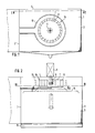
- the steam cooking appliance consists of a closed room with a rear wall 1, with side walls 2 and 3, a ceiling 4, a floor 5 and a door 17 on the front.
- a paddle wheel 18 is mounted on the rear wall 1, which has a hub 6, a disk 7 and peripheral blades 8.
- an electric motor 9 is provided, which is arranged outside the housing.
- the paddle wheel 18 is surrounded by a heater 10.
- the paddle wheel with the heater 10 is separated from the actual cooking space, into which the food can be introduced, via a removable cover 15.
- the cover 15 is formed so that air (and steam) circulation through the impeller 18 can be maintained.
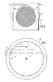
- the suction opening of the cover 15 is shown in Fig. 2 with a broken line to indicate that a relatively close-meshed and preferably multi-layer sieve is attached here, which is intended to keep food and fat particles from the air stream entering the impeller 18.
- FIGS. 2 and 3 there is a further sieve 21 behind the grease filter just described.
- a water supply line 13 with two outlet openings 14a and 14b is arranged in such a way that from the water outlet openings 14a, 14b escaping water is led directly to the sieve 21.
- the sieve 21 is designed in this case (diagonal lattice courses) in such a way that the outflowing water is distributed downwards over an increasing area when flowing. In the course of its descent, the water is entrained by the air flow, which passes through the mesh of the sieve and has a higher flow velocity (and therefore a lower pressure) there than in front of and behind the individual sieve rods. The water entering the air stream in this way is further distributed by the blades 8 and supplied to the heater 10. Expanded metal of appropriate shape is also particularly suitable as the sieve 21.
- a trickle cascade 22 is provided in the area of the suction opening of the fan impeller 18. This is over a group of flow plates 23, 24, 25 and 26 constructed in a manner known per se and arranged so that water which flows from the outlet opening 14 into the uppermost flow plate 23 can flow over the edges thereof and into two flow plates 24 underneath . From the two trickle plates 24, the water gets into four trickle plates 25 and from there into eight trickle plates 26. The water stream thus divided is finely divided enough to be entrained by the air flowing into the fan impeller 18 before the individual drops of water fall to the ground .
- a water outflow body 27 is located essentially in the center within the fan impeller 18.
- the water outflow body 27 is essentially cylindrical with a relatively large diameter and has in outlet openings 14a, 14b, 14c etc. in its upper region.
- the outlet openings 14a-14c are separated from one another by means of partition walls 28, so that water which flows downward from the outlet openings 14a-14c the peripheral wall of the water outflow body 27 (on both sides) always remains separated from the neighboring stream. Because the water outflow body 27 is located in the center of the blower impeller 18, it lies precisely in the area in which a vortex flow forms around the water outflow body 27 when the blower impeller 18 is in operation. As a result, air flows around the water outlet body 27 and takes water with it in finely divided form, which is then blown together with the required air in the direction of the heater 10.
- an essential point of the invention is that water is atomized and distributed at least to a certain extent with the aid of the air (or steam) flow which is anyway necessary during the operation of the steam cooking device the fan impeller a further and at the latest then sufficient fine distribution of the water is possible.
Landscapes
- Engineering & Computer Science (AREA)
- Chemical & Material Sciences (AREA)
- Combustion & Propulsion (AREA)
- Mechanical Engineering (AREA)
- General Engineering & Computer Science (AREA)
- Food Science & Technology (AREA)
- Structures Of Non-Positive Displacement Pumps (AREA)
- Ventilation (AREA)
- Baking, Grill, Roasting (AREA)
- Commercial Cooking Devices (AREA)
Applications Claiming Priority (2)
| Application Number | Priority Date | Filing Date | Title |
|---|---|---|---|
| DE4013596 | 1990-04-27 | ||
| DE4013596A DE4013596A1 (de) | 1990-04-27 | 1990-04-27 | Dampf-gargeraet |
Publications (2)
| Publication Number | Publication Date |
|---|---|
| EP0457971A1 true EP0457971A1 (fr) | 1991-11-27 |
| EP0457971B1 EP0457971B1 (fr) | 1994-05-04 |
Family
ID=6405294
Family Applications (1)
| Application Number | Title | Priority Date | Filing Date |
|---|---|---|---|
| EP90125549A Expired - Lifetime EP0457971B1 (fr) | 1990-04-27 | 1990-12-27 | Appareil de cuisson à vapeur |
Country Status (2)
| Country | Link |
|---|---|
| EP (1) | EP0457971B1 (fr) |
| DE (3) | DE9007558U1 (fr) |
Cited By (5)
| Publication number | Priority date | Publication date | Assignee | Title |
|---|---|---|---|---|
| EP0640310A1 (fr) * | 1993-08-05 | 1995-03-01 | ANGELO PO GRANDI CUCINE S.p.A. | Four à convection et vapeur pour aliments |
| US5530223A (en) * | 1993-08-05 | 1996-06-25 | Angelo Po Grandi Cucine S.P.A. | Convection and steam oven with a pre-atomizer |
| WO2003046438A1 (fr) * | 2001-11-29 | 2003-06-05 | Mkn Maschinenfabrik Kurt Neubauer Gmbh & Co. | Appareil de cuisson a soufflante et arrivee d'eau |
| EP1616515A1 (fr) * | 2004-07-15 | 2006-01-18 | BSH Bosch und Siemens Hausgeräte GmbH | Cuisseur à vapeur |
| CN110558821A (zh) * | 2019-09-15 | 2019-12-13 | 宁波方太厨具有限公司 | 一种热风挡板及具有该热风挡板的烹饪装置 |
Families Citing this family (2)
| Publication number | Priority date | Publication date | Assignee | Title |
|---|---|---|---|---|
| DE4124896C1 (fr) * | 1991-07-26 | 1993-01-21 | Eloma Gmbh Bedarfsartikel Zur Gemeinschaftsverpflegung, 8031 Maisach, De | |
| DE102009000275B4 (de) * | 2009-01-16 | 2025-03-13 | BSH Hausgeräte GmbH | Gargerät mit Zerstäubungseinrichtung |
Citations (4)
| Publication number | Priority date | Publication date | Assignee | Title |
|---|---|---|---|---|
| GB542533A (en) * | 1940-07-29 | 1942-01-14 | John Ambrose Sadd | Improvements in apparatus for spraying liquids |
| EP0244538A2 (fr) * | 1986-05-09 | 1987-11-11 | Eloma GmbH Bedarfsartikel zur Gemeinschaftsverpflegung | Four à vapeur et convection combinées |
| DE3700894A1 (de) * | 1986-02-19 | 1987-12-10 | Eloma Gmbh | Geraet zum garen von nahrungsmitteln und verfahren zum betrieb des geraetes |
| EP0278889A1 (fr) * | 1987-02-03 | 1988-08-17 | Air Industrie Systemes | Dispositif de lavage d'un gaz pollué |
-
1990
- 1990-04-27 DE DE9007558U patent/DE9007558U1/de not_active Expired - Lifetime
- 1990-04-27 DE DE4013596A patent/DE4013596A1/de active Granted
- 1990-12-27 EP EP90125549A patent/EP0457971B1/fr not_active Expired - Lifetime
- 1990-12-27 DE DE59005638T patent/DE59005638D1/de not_active Expired - Fee Related
Patent Citations (4)
| Publication number | Priority date | Publication date | Assignee | Title |
|---|---|---|---|---|
| GB542533A (en) * | 1940-07-29 | 1942-01-14 | John Ambrose Sadd | Improvements in apparatus for spraying liquids |
| DE3700894A1 (de) * | 1986-02-19 | 1987-12-10 | Eloma Gmbh | Geraet zum garen von nahrungsmitteln und verfahren zum betrieb des geraetes |
| EP0244538A2 (fr) * | 1986-05-09 | 1987-11-11 | Eloma GmbH Bedarfsartikel zur Gemeinschaftsverpflegung | Four à vapeur et convection combinées |
| EP0278889A1 (fr) * | 1987-02-03 | 1988-08-17 | Air Industrie Systemes | Dispositif de lavage d'un gaz pollué |
Cited By (7)
| Publication number | Priority date | Publication date | Assignee | Title |
|---|---|---|---|---|
| EP0640310A1 (fr) * | 1993-08-05 | 1995-03-01 | ANGELO PO GRANDI CUCINE S.p.A. | Four à convection et vapeur pour aliments |
| US5530223A (en) * | 1993-08-05 | 1996-06-25 | Angelo Po Grandi Cucine S.P.A. | Convection and steam oven with a pre-atomizer |
| WO2003046438A1 (fr) * | 2001-11-29 | 2003-06-05 | Mkn Maschinenfabrik Kurt Neubauer Gmbh & Co. | Appareil de cuisson a soufflante et arrivee d'eau |
| US7325481B2 (en) | 2001-11-29 | 2008-02-05 | Mkn Maschinenfabrik Kurt Neubauer Gmbh & Co. | Cooking device with a fan and a water supply |
| EP1616515A1 (fr) * | 2004-07-15 | 2006-01-18 | BSH Bosch und Siemens Hausgeräte GmbH | Cuisseur à vapeur |
| CN110558821A (zh) * | 2019-09-15 | 2019-12-13 | 宁波方太厨具有限公司 | 一种热风挡板及具有该热风挡板的烹饪装置 |
| CN110558821B (zh) * | 2019-09-15 | 2021-01-19 | 宁波方太厨具有限公司 | 一种热风挡板及具有该热风挡板的烹饪装置 |
Also Published As
| Publication number | Publication date |
|---|---|
| DE4013596A1 (de) | 1991-10-31 |
| DE59005638D1 (de) | 1994-06-09 |
| DE4013596C2 (fr) | 1993-01-07 |
| DE9007558U1 (de) | 1992-08-13 |
| EP0457971B1 (fr) | 1994-05-04 |
Similar Documents
| Publication | Publication Date | Title |
|---|---|---|
| EP0118570B1 (fr) | Hotte d'évacuation à circulation d'air | |
| DE2016126A1 (de) | Verfahren und Vorrichtung zur Kontaktbehandlung von Medien mit unterschiedlicher Dichte | |
| DE3603112A1 (de) | Geraet zum befeuchten und reinigen von raumluft | |
| DE1205058B (de) | Vorrichtung zum Umwaelzen und Belueften einer Fluessigkeit in einem Behaelter | |
| DE4203916C1 (fr) | ||
| EP0833110B1 (fr) | Four avec un dispositif soufflant | |
| DE4013596C2 (fr) | ||
| DE2932803C2 (de) | Wirbelschichtapparatur | |
| DE2002056B2 (de) | Zerstäubungskühler, insbesondere Kühlturm zur Abkühlung von Wasser | |
| EP3620721A1 (fr) | Dispositif d'aspiration de cuves de l'air extrait sur une plaque de cuisson | |
| DE2339446B2 (de) | Umluftofen zum garen von lebensmitteln | |
| AT396736B (de) | Vorrichtung zum abscheiden von dunst-, fett- und staubpartikeln aus einem luftstrom | |
| AT522780B1 (de) | Vorrichtung zur reinigung von gas | |
| DE4013595C2 (de) | Dampf-Gargerät | |
| EP0640310B1 (fr) | Four à convection et vapeur pour aliments | |
| EP0172900B1 (fr) | Installation pour le transport et/ou le melange de gaz | |
| EP0271652B1 (fr) | Dispositif de production d'un courant de renouvelement d'air | |
| EP0070870A1 (fr) | Dispositif pour aspirer du brouillard de peinture. | |
| DE4312825C1 (de) | Anordnung zur Luftzufuhr bei einem Radialgebläse oder dergleichen | |
| EP0237018A2 (fr) | Dispositif pour la déshydratation et le séchage de matières solides, notamment des matières synthétiques obtenues par granulation sous l'eau | |
| DE1619719B2 (fr) | ||
| EP1529183B1 (fr) | Appareil de cuisson avec dispositif integre de separation de la graisse | |
| AT525252B1 (de) | Abscheidevorrichtung | |
| AT361887B (de) | Motorlose einrichtung zum verteilen der aus- blasluft an staubsaugern | |
| DE1685948C3 (de) | Mit Blas- und Saugluft arbeitende Reinigungsvorrichtung für Spinnmaschinen |
Legal Events
| Date | Code | Title | Description |
|---|---|---|---|
| PUAI | Public reference made under article 153(3) epc to a published international application that has entered the european phase |
Free format text: ORIGINAL CODE: 0009012 |
|
| 17P | Request for examination filed |
Effective date: 19901227 |
|
| AK | Designated contracting states |
Kind code of ref document: A1 Designated state(s): CH DE FR IT LI |
|
| 17Q | First examination report despatched |
Effective date: 19930511 |
|
| GRAA | (expected) grant |
Free format text: ORIGINAL CODE: 0009210 |
|
| AK | Designated contracting states |
Kind code of ref document: B1 Designated state(s): CH DE FR IT LI |
|
| ITF | It: translation for a ep patent filed | ||
| ET | Fr: translation filed | ||
| REF | Corresponds to: |
Ref document number: 59005638 Country of ref document: DE Date of ref document: 19940609 |
|
| PG25 | Lapsed in a contracting state [announced via postgrant information from national office to epo] |
Ref country code: LI Effective date: 19941231 Ref country code: CH Effective date: 19941231 |
|
| PLBE | No opposition filed within time limit |
Free format text: ORIGINAL CODE: 0009261 |
|
| STAA | Information on the status of an ep patent application or granted ep patent |
Free format text: STATUS: NO OPPOSITION FILED WITHIN TIME LIMIT |
|
| 26N | No opposition filed | ||
| PG25 | Lapsed in a contracting state [announced via postgrant information from national office to epo] |
Ref country code: FR Effective date: 19950831 |
|
| REG | Reference to a national code |
Ref country code: CH Ref legal event code: PL |
|
| PG25 | Lapsed in a contracting state [announced via postgrant information from national office to epo] |
Ref country code: DE Effective date: 19950901 |
|
| REG | Reference to a national code |
Ref country code: FR Ref legal event code: ST |
|
| PG25 | Lapsed in a contracting state [announced via postgrant information from national office to epo] |
Ref country code: IT Free format text: LAPSE BECAUSE OF NON-PAYMENT OF DUE FEES;WARNING: LAPSES OF ITALIAN PATENTS WITH EFFECTIVE DATE BEFORE 2007 MAY HAVE OCCURRED AT ANY TIME BEFORE 2007. THE CORRECT EFFECTIVE DATE MAY BE DIFFERENT FROM THE ONE RECORDED. Effective date: 20051227 |