EP0640310A1 - Four à convection et vapeur pour aliments - Google Patents
Four à convection et vapeur pour aliments Download PDFInfo
- Publication number
- EP0640310A1 EP0640310A1 EP94107706A EP94107706A EP0640310A1 EP 0640310 A1 EP0640310 A1 EP 0640310A1 EP 94107706 A EP94107706 A EP 94107706A EP 94107706 A EP94107706 A EP 94107706A EP 0640310 A1 EP0640310 A1 EP 0640310A1
- Authority
- EP
- European Patent Office
- Prior art keywords
- convection
- steam oven
- oven according
- fan
- ball
- Prior art date
- Legal status (The legal status is an assumption and is not a legal conclusion. Google has not performed a legal analysis and makes no representation as to the accuracy of the status listed.)
- Granted
Links
- 235000013305 food Nutrition 0.000 title claims abstract description 6
- 238000002360 preparation method Methods 0.000 title abstract 2
- XLYOFNOQVPJJNP-UHFFFAOYSA-N water Substances O XLYOFNOQVPJJNP-UHFFFAOYSA-N 0.000 claims abstract description 45
- 238000000889 atomisation Methods 0.000 claims abstract description 34
- 238000010438 heat treatment Methods 0.000 claims abstract description 11
- 230000002093 peripheral effect Effects 0.000 claims description 7
- 239000002184 metal Substances 0.000 claims description 2
- 239000004033 plastic Substances 0.000 claims description 2
- UQMRAFJOBWOFNS-UHFFFAOYSA-N butyl 2-(2,4-dichlorophenoxy)acetate Chemical compound CCCCOC(=O)COC1=CC=C(Cl)C=C1Cl UQMRAFJOBWOFNS-UHFFFAOYSA-N 0.000 description 5
- 238000010276 construction Methods 0.000 description 4
- 238000009826 distribution Methods 0.000 description 4
- 230000000694 effects Effects 0.000 description 4
- 239000002245 particle Substances 0.000 description 4
- 239000012808 vapor phase Substances 0.000 description 3
- 235000008733 Citrus aurantifolia Nutrition 0.000 description 2
- 235000011941 Tilia x europaea Nutrition 0.000 description 2
- 239000004571 lime Substances 0.000 description 2
- 230000004048 modification Effects 0.000 description 2
- 238000012986 modification Methods 0.000 description 2
- 238000005192 partition Methods 0.000 description 2
- 239000004809 Teflon Substances 0.000 description 1
- 229920006362 Teflon® Polymers 0.000 description 1
- 229920001343 polytetrafluoroethylene Polymers 0.000 description 1
- 239000004810 polytetrafluoroethylene Substances 0.000 description 1
- 238000009827 uniform distribution Methods 0.000 description 1
- 238000009423 ventilation Methods 0.000 description 1
Images


Classifications
-
- F—MECHANICAL ENGINEERING; LIGHTING; HEATING; WEAPONS; BLASTING
- F24—HEATING; RANGES; VENTILATING
- F24C—DOMESTIC STOVES OR RANGES ; DETAILS OF DOMESTIC STOVES OR RANGES, OF GENERAL APPLICATION
- F24C15/00—Details
- F24C15/32—Arrangements of ducts for hot gases, e.g. in or around baking ovens
- F24C15/322—Arrangements of ducts for hot gases, e.g. in or around baking ovens with forced circulation
- F24C15/327—Arrangements of ducts for hot gases, e.g. in or around baking ovens with forced circulation with air moisturising
-
- A—HUMAN NECESSITIES
- A21—BAKING; EDIBLE DOUGHS
- A21B—BAKERS' OVENS; MACHINES OR EQUIPMENT FOR BAKING
- A21B3/00—Parts or accessories of ovens
- A21B3/04—Air-treatment devices for ovens, e.g. regulating humidity
-
- A—HUMAN NECESSITIES
- A47—FURNITURE; DOMESTIC ARTICLES OR APPLIANCES; COFFEE MILLS; SPICE MILLS; SUCTION CLEANERS IN GENERAL
- A47J—KITCHEN EQUIPMENT; COFFEE MILLS; SPICE MILLS; APPARATUS FOR MAKING BEVERAGES
- A47J27/00—Cooking-vessels
- A47J27/14—Cooking-vessels for use in hotels, restaurants, or canteens
- A47J27/16—Cooking-vessels for use in hotels, restaurants, or canteens heated by steam
Definitions
- the invention relates to a convection and steam oven for foodstuffs with an oven space and an adjoining room separated from it, in which a motor-driven, radially acting fan is arranged around a plurality of heating elements surrounding it, with a pre-atomizing element rotating therewith for optionally consisting of one on the hub of the fan Pipeline is arranged on this water.
- the end of the water supply line is guided into this cup element.
- the rotating cup element has an edge part and an inner surface that tapers away from the edge part so that a volume of water can collect in the cup and so that after filling up the water volume, the excess water flows over the edge and thereby forms a water film that is atomized by centrifugal force.
- the water which has been pre-atomized in this way then hits the blades of the radial-acting fan arranged in a ring and is further crushed there, as previously explained.
- a generic convection and steam oven is also known from the Italian utility model application 40 052A / 90.
- an overpressure is built up here in the oven space, so that the steam formed in the adjoining room and distributed over the oven space can be overheated.
- the pressure increase in the furnace chamber of approx. 5 mbar leads to a more even distribution of the steam atmosphere.
- the pre-atomization element is formed here by a drum which also rotates on the axis of the fan and which has a multiplicity of slot-like openings distributed uniformly over the circumference. The water is fed in from the pipeline at the open end of the drum provided with the openings.
- the water flowing out of the tube is entrained by the air flow sucked in from the center by the radially acting fan and is guided through the slot-like openings in the drum wall, the water being atomized at the slot-like openings.
- the previously known pre-atomization element according to EP 244 538 B1 not only a water film tearing off over the edge of a cup is formed here. Rather, the entire length of the Elongated holes achieve an atomization effect, so that the water drops so pre-atomized hit the fan blades evenly distributed.
- better atomization is achieved because, due to another principle of pre-atomization, the entire depth of the radially acting circular fan is used.
- both of the previously described embodiments have the disadvantage that they calcify after a relatively short service life and then have to be replaced.
- the lime deposits preferably in the outlet area of the pipe, that is to say at the open end of the closed cup or the drum provided with openings.
- Even a realized embodiment that differs from the Italian utility model application, in which the drum has a conical shape that widens outwards, does not lead to any remedy here.
- the limescale layer that builds up is so thick within a short time that the entire device is no longer functional.
- a convection and steam oven of the generic type is also known from EP 233 535 B.
- no specially designed pre-atomizing element is provided. Rather, the water is applied to the fan hub.
- the outlet opening of the water supply is directed radially from the outside towards the hub and the outlet opening of the water supply is arranged above the hub. This is hoped that the water flowing out of the outlet opening can fall from above onto the hub rotating with the fan and is atomized by the latter.
- This known convection and steam oven leads to an unsatisfactory pre-atomization effect.
- a pre-atomization element specially formed for the pre-atomization is arranged on the hub of the fan.
- This consists of a body with a convex surface. It has surprisingly been found that the water dripping onto a convex body is already very finely atomized due to the rotational movement of this body. It is crucial here that the limescale layers forming on the pre-atomization element do not lead to clogging and inoperability, but build up on the convex surface and lead to additional irregularities on the convex surface, which rather improve the pre-atomization effect.
- the convex body is designed as a sphere.
- a web enveloping the ball can be arranged which intersects the axis of rotation of the ball at an angle ( ⁇ ) which is greater than 0 ° and less than 90 °.
- ⁇ angle
- the ball can be fastened to the drive shaft of the fan via a cylinder extension piece.
- the outlet opening of the water to be evaporated When viewed in the direction of the axis of rotation, the pipeline can be arranged next to the ball and directed axially towards the ball. The water drops flowing out of the outlet opening are thus caught by the air flow flowing axially into the fan wheel and directed to the correspondingly shaped pre-atomizing element.
- the ball can particularly advantageously be composed of two hemispherical shells, with both hemispherical shells being delimited by a peripheral edge.
- the two hemispherical shells can be connected to one another in a cohesive and / or positive manner along the edges lying one on top of the other.
- a ball is given in a very simple manner, which has the above-mentioned enveloping web.
- the hemispherical shells can advantageously have two openings, one opening being adapted to a shaft extension of the fan rotation shaft and a mounting screw for mounting the ball being guided through the other opening.
- the cylinder extension that was mentioned earlier is dispensed with.
- the surface of the ball can be partially flattened.
- the pre-atomizing element can also consist of a hemisphere.
- the line of symmetry of the hemisphere can coincide with the axis of rotation.
- the line of symmetry of the hemisphere can also be set at an angle ( ⁇ ) to the axis of rotation.
- the hemisphere can advantageously be produced from a hemisphere shell with a peripheral edge and a circular plate which is flush with this peripheral edge and is integrally connected to it.
- a generic convection and steam oven as a pre-atomizing element has a preferably circular plate which is positioned obliquely to the axis of rotation of the fan and above which the pipeline ends.
- a uniform distribution over the depth of the fan ring is achieved in particular with radial fans of less depth.
- a rod, a tongue or a further tube can be attached to the side of the outlet opening of the pipeline facing the axis of rotation of the fan.
- the rod, the tongue or the further tube serve to further guide the drops, since the drops emerging from the pipeline roll off along the rod, the tongue or the additional tube and are guided from the rod, the tongue or the additional tube to the pre-atomizing element .
- the free end of the rod, the tongue or the further tube advantageously extends approximately up to the axis of rotation of the fan.
- the rod, the tongue or the further tube can be elastic and optionally made of rubber.
- the tongue is also to be understood as a channel, which can optionally be elastic and / or can be suspended in a swinging manner on the tube.
- the rod is made of metal.
- This particular embodiment of the invention enables a further additional atomization mechanism. So the drops, which are passed over the rod, the tongue or the pipe and come into contact primarily with the rotating element. The rotation of the pre-atomization element leads to further atomization.
- One end of the ball can be flattened, the flattening being opposite the outlet opening of the pipeline.
- the plane of the outlet opening can thus be formed parallel to the plane of the flattening.
- the pipe outlet opening can also be chamfered.
- the ball in the axis of rotation can have a recess directed into the inside of the ball, the rod extending into this recess. This further improves the transfer of the water drops to be directed onto the pre-atomization element.
- a special embodiment of the invention is that the pipeline is pulled down to the level of the axis of rotation of the fan and a cup open to the pre-atomizing element is only attached approximately at the level of the axis of rotation of the fan.
- the axes of symmetry of the pre-atomization element and the cup can intersect at approximately a right angle.
- the pipeline and the attached cup are designed such that the water runs through the pipeline into the cup connected to it, which guides it in the immediate vicinity of the pre-atomizing element.
- the cup can preferably be made of rubber or plastic, such as Teflon, PTFE.
- the open edge of the cup can be beveled and part of the edge can be arranged directly next to the pre-atomizing element.
- a pipe open at both ends can also be attached in the pipeline.
- This can have a funnel-shaped inner wall, the inner diameter widening toward the pre-atomizing element. This ensures that the water entering the open pipe from the pipeline flows towards the pre-atomizing element.
- the design as an open tube has the advantage over the cup closed on one side that air sucked in by the fan flows through the tube in the direction of the pre-atomizing element.
- a collecting trough can be arranged below the outlet opening in the region of the axis of symmetry of the pre-atomizing element, the lower edge of which near the Pre-atomization element ends. This collecting trough is advantageously screwed onto the pipeline via an elastic holding element.
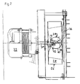
- the convection and steam oven 10 comprises an oven chamber 12, in which 14 plates 16 or grids are slidably guided in a known manner on slide rails.
- An adjoining room 20 is separated from the furnace room by a partition 18.
- This secondary room 20 is connected to the furnace chamber via circumferential slots 22 and a central opening 24.
- a radial fan 26 is arranged in the adjoining room 20 and has fan blades 28 arranged on a circular circumference.
- the fan 26 is flanged onto a hub 30 which is driven by a motor 32.
- a pre-atomizing element 34 is also arranged on the fan hub, over which a pipeline 36, into which water to be evaporated is introduced, ends.
- Heating coils 38 are placed around the fan 26 and are gas-heated or electrically heated, for example.
- the oven 10 can be operated as a convection oven in that, by means of the radial fan 26, air is passed over the heating coils 38, where it is heated.
- the heated air enters the furnace chamber 12 through the gap 22 surrounding the wall 18.
- the air is drawn in by the fan 26 out of the furnace space and deflected in the direction of the fan blades 28.
- FIGS. 2 to 8 Different embodiments of the pre-atomization element result from FIGS. 2 to 8.
- FIGS. 2 to 8 only the details essential for atomization are shown.
- the heating elements 38 have not been shown here, for example.
- a pre-atomizing element 34 which is composed of two hemispherical shells 40, is mounted on the fan shaft 30 driven by the motor 32, both hemispherical shells being delimited by a peripheral edge 42.
- the two hemispherical shells are integrally connected to one another along the edges 42 lying one on top of the other.
- a web is formed which surrounds the surface of the ball and which, as can be seen in FIG. 2, intersects the axis of rotation of the ball at an angle which in this exemplary embodiment is approximately 60 °.
- the hemispherical shells have two openings, one opening being adapted to the shaft extension of the fan rotation shaft 30. In the exemplary embodiment shown here in FIG.
- a fastening flange 46 for the fan 26 is seated on the shaft shoulder, to which the opening of the hemisphere shell 40 is then adapted.
- a screw 44 is guided through the other hemisphere shell 40 and can be screwed into a corresponding bore within the mounting flange 46 and thus fixes the sphere composed of the two hemisphere shells.
- the pipe 36 through which the water is fed onto the pre-atomizing element 34, opens out above the axis of rotation.
- the pipe is arranged parallel to the fan and in its end area bent towards the pre-atomizing element 34.
- the tube 36 ends approximately in the area of the outer edge of the fan 26, as shown in more detail in FIG. 2. In the exemplary embodiment shown in FIG.
- the atomizing element 34 extends almost over the entire depth of the fan 26. This corresponds to an embodiment which is intended in particular for smaller ovens 10.
- the fan 26 and thus also the pre-atomizing element 34 runs at speeds of approximately 2800 revolutions per minute.
- the overall dimensions of the small ovens are approx. 50 cm deep, 50 cm high and 70 cm wide. The external dimensions are given here accordingly.
- the embodiment according to FIG. 3 essentially corresponds to that according to FIG. 2. However, this is an embodiment in particular for comparatively larger stoves.
- the pre-atomizing element 34 here again consists of a ball with an encasing web, which again consists of hemispherical shells 40 and spherical bodies joined along the protruding edge 42.
- a cylinder extension 46 'aligned in the axis of rotation, over one side of which a screw bolt 48 is attached, to which the pre-atomizing element 34 is screwed into the fan flange 36.
- FIG. 4 essentially corresponds to that according to FIG. 3 and is also intended for comparatively larger stoves.
- the speed corresponds to that according to the embodiment according to FIG. 3.
- Ball 50 is provided, which has no enveloping web. Otherwise, this variant corresponds to that which has already been described with reference to FIG. 3.
- the embodiment variant according to FIG. 5 corresponds to that according to FIGS. 3 and 4 and is also preferably used for the large construction variant of the furnace.
- a ball with flattened surfaces is used as the pre-atomizing element 34.
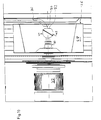
- the pre-atomizing element 34 has the shape of a hemisphere. This is formed from a hemispherical shell 40 with a peripheral edge 42, to which a circular plate 52 is connected flush. On this plate 52 sits a cylinder extension 46 ', which is screwed into the fan flange 46 via a bolt 48 formed thereon. As shown in FIG. 6, the hemisphere is tilted with respect to the axis of rotation. The line of symmetry of the hemisphere forms an angle ⁇ of 15 ° with the axis of rotation.
- the water pipe 36 opens above the pre-atomizing element 34, as shown in FIG. 6.
- the embodiment according to FIG. 7 largely corresponds to the embodiment previously explained with reference to FIG. 6. Here, however, no edge is formed on the hemisphere shell 40 and the axis of symmetry of the hemisphere shell 40 coincides with the axis of rotation. Otherwise, the embodiment according to FIG. 7 corresponds to that according to FIG. 6.
- FIG. 1 Another variant of the atomizing device 34 is shown in FIG. There, a circular plate 60 is provided on a cylinder extension 46 'at an angle to the axis of rotation.
- the water supply pipe 36 opens above the outer periphery of the rotating plate 60 as shown in FIG.
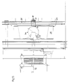
- FIGS. 9 to 12 show further alternatives for embodiments of a convection or steam oven according to the invention.
- the convection and steam oven comprises an oven space in which are guided in a known manner on sliding rails, sheets or grids.
- a side room is separated from the furnace room by a partition.
- This adjoining room is connected to the furnace room via circumferential slots and a central opening.
- a radially acting fan designated 26 in FIGS. 9-12, is arranged.
- This has fan blades 28 arranged on a circumference.
- the fan 26 is flanged onto a fan hub 30 which is driven by a rotor 32.
- a pre-atomizing element 34 is arranged on the fan axis, next to which the outlet opening of a pipeline 36 in which water to be evaporated is filled ends in the direction of the axis of rotation.
- heating coils 38 are placed, which are gas-heated or electrically heated, for example.
- the oven can be operated as a convection oven in which air is passed over the heating coils by means of the radial fan 26, where it is heated. The heated air enters the furnace chamber through the gap around the wall. In the area of the breakthrough, the air is drawn in by the fan from the furnace space and deflected in the direction of the fan blades 28.
- a pre-atomizing element 34 is mounted on the fan shaft 30 driven by the motor 32, which element is composed of two hemispherical shells 40, both hemispherical shells being delimited by a peripheral edge 42.
- the two hemispherical shells are integrally connected to one another along the edges 42 lying one on top of the other.
- a web is formed which surrounds the surface of the ball and which, as can be seen in FIG. 10, intersects the axis of rotation of the ball at an angle ⁇ , which in this exemplary embodiment is approximately 60 °.
- a pre-atomization element is thus formed here in the form of a ball, on the surface of which a web surrounding it is arranged.
- the outlet opening of the pipeline 36 is arranged next to the ball in the direction of the axis of rotation, as can be seen in FIG. 1.
- a rod 70 is attached to the side of the outlet opening of the pipeline facing the axis of rotation of the fan 26.
- the free end of the rod 70 extends approximately to the axis of rotation of the fan 26.
- the water drops emerging from the outlet opening of the pipeline 36 are guided via this rod in the direction of the pre-atomizing element 34. Otherwise, they are entrained by the axially inflowing air in the direction of the pre-atomization element.
- the pre-atomization element 34 has a flat 72, so that essentially a ball with a flat on one side results.
- the flat 72 is arranged opposite the outlet opening of the pipeline 36.
- FIGS. 11 and 11a A further modification of the pre-atomizing element is shown in FIGS. 11 and 11a.
- the web 42 enveloping the ball which is comparatively wider, has openings 74 along the circular ring forming the web.
- FIG. 12 shows another modification of the exemplary embodiment according to FIG. 9, which consists in that the spherical pre-atomizing element 34 has a recess 76 directed towards the inside of the sphere in the direction of the rotational axis and that the rod 70 extends into this recess.
- the pre-atomizing element 34 is designed in accordance with the embodiment according to FIG. 1.
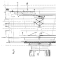
- the pipeline 36 is modified. 13
- the pipeline is pulled down parallel to the walls forming the furnace space to approximately the height of the line of symmetry of the pre-atomizing element 34 designed as a ball.
- the beveled tip of the pipeline 36 opens into a cup 80.
- the cup 80 has a bevelled edge 82 which points towards the pre-atomizing element 34.
- a portion of the border 82 can, as shown in FIG. 13, rest on the surface of the pre-atomizing element 34.
- the rubber cup 80 can be connected to the pipeline 36 via a clamping screw 84.
- This arrangement ensures that the water flowing in through the pipe 36 is brought into contact with the pre-atomizing element via the cavity of the cup. After the forced contact with the pre-atomization element 34, the latter is flung away from the surface of the pre-atomization element 34 and is thereby already atomized.
- FIG. 14 shows a modified form of a cup, which can be described as a tube piece 80 '.
- the pipe section 80 ' is funnel-shaped on the inside. This ensures that the water runs along the funnel widening towards the pre-atomizing element 34. This will direct the water to the pre-atomization element. The water is additionally dragged along by the air sucked in through the pipeline 80 ′, which is sucked in due to the ventilation effect of the fan 28.
- the pipe section is also connected to the pipe 36 via a clamping screw 84 '.
- the pipe section 80 ' is also made of rubber here.
- FIG. 15 An embodiment is shown in FIG. 15, in which the pipeline 36 also corresponds to the course as was shown in FIG. 1.
- a trough-shaped element 86 made of rubber is arranged below the outlet opening of the pipeline 36, which rests with an edge 88 on the surface of the pre-atomizing element 34.
- the trough-shaped element 86 is screwed onto the pipe 36 via a holding plate 90.
- the water emerging from the outlet opening of the pipeline 36 drops onto the trough-shaped element 86 and, as shown in FIG. 15, is forcibly brought into contact with the pre-atomizing element 34 by this.
Landscapes
- Engineering & Computer Science (AREA)
- Food Science & Technology (AREA)
- Life Sciences & Earth Sciences (AREA)
- Chemical & Material Sciences (AREA)
- Combustion & Propulsion (AREA)
- Mechanical Engineering (AREA)
- General Engineering & Computer Science (AREA)
- General Preparation And Processing Of Foods (AREA)
- Air Humidification (AREA)
- Baking, Grill, Roasting (AREA)
- Nozzles (AREA)
- Electric Ovens (AREA)
Priority Applications (1)
| Application Number | Priority Date | Filing Date | Title |
|---|---|---|---|
| US08/286,749 US5530223A (en) | 1993-08-05 | 1994-08-05 | Convection and steam oven with a pre-atomizer |
Applications Claiming Priority (6)
| Application Number | Priority Date | Filing Date | Title |
|---|---|---|---|
| DE9311711U | 1993-08-05 | ||
| DE19939311711 DE9311711U1 (de) | 1993-08-05 | 1993-08-05 | Konvektions- und Dampfofen für Lebensmittel |
| DE9316958U | 1993-11-05 | ||
| DE9316958 | 1993-11-05 | ||
| DE9402624U | 1994-02-17 | ||
| DE9402624U DE9402624U1 (de) | 1993-11-05 | 1994-02-17 | Konvektions- und Dampfofen für Lebensmittel |
Publications (2)
| Publication Number | Publication Date |
|---|---|
| EP0640310A1 true EP0640310A1 (fr) | 1995-03-01 |
| EP0640310B1 EP0640310B1 (fr) | 1998-11-04 |
Family
ID=27208620
Family Applications (1)
| Application Number | Title | Priority Date | Filing Date |
|---|---|---|---|
| EP94107706A Expired - Lifetime EP0640310B1 (fr) | 1993-08-05 | 1994-05-18 | Four à convection et vapeur pour aliments |
Country Status (5)
| Country | Link |
|---|---|
| EP (1) | EP0640310B1 (fr) |
| AT (1) | ATE172857T1 (fr) |
| DE (1) | DE59407216D1 (fr) |
| DK (1) | DK0640310T3 (fr) |
| ES (1) | ES2124337T3 (fr) |
Cited By (7)
| Publication number | Priority date | Publication date | Assignee | Title |
|---|---|---|---|---|
| WO1997033479A1 (fr) * | 1996-03-12 | 1997-09-18 | Aktiebolaget Electrolux | Generateur de vapeur |
| EP0893084A1 (fr) | 1997-07-23 | 1999-01-27 | Gaggenau Hausgeräte GmbH | Four de cuisson à vapeur avec un générateur de vapeur |
| FR2775760A1 (fr) * | 1998-03-09 | 1999-09-10 | Bourgeois Prod Coop | Four a vapeur a repartiteur fixe de l'eau a vaporiser |
| WO2003046438A1 (fr) * | 2001-11-29 | 2003-06-05 | Mkn Maschinenfabrik Kurt Neubauer Gmbh & Co. | Appareil de cuisson a soufflante et arrivee d'eau |
| EP1726886A1 (fr) * | 2005-05-27 | 2006-11-29 | Unox S.p.A. | Objet de fixation, spécialement pour la fixation d'un élément tubulaire dans le moufle d'un four cuisinièr |
| EP1970634A3 (fr) * | 2007-03-15 | 2010-12-15 | ANGELO PO GRANDI CUCINE S.p.A. | Four pour cuire des aliments |
| US9372005B2 (en) | 2012-11-30 | 2016-06-21 | Alto-Shaam, Inc. | Heat exchanger for oven |
Citations (5)
| Publication number | Priority date | Publication date | Assignee | Title |
|---|---|---|---|---|
| US4671250A (en) * | 1986-07-28 | 1987-06-09 | Thermo Electron Corporation | Direct-firing gas convection oven |
| EP0457971A1 (fr) * | 1990-04-27 | 1991-11-27 | ELOMA GmbH BEDARFSARTIKEL ZUR GEMEINSCHAFTSVERPFLEGUNG | Appareil de cuisson à vapeur |
| EP0523489A1 (fr) * | 1991-07-17 | 1993-01-20 | ZANUSSI GRANDI IMPIANTI S.p.A. | Arrangement de générateur de vapeur pour appareils de cuisson d'aliments, en particulier fours et appareils similaires |
| EP0530477A1 (fr) * | 1991-07-26 | 1993-03-10 | ELOMA GmbH BEDARFSARTIKEL ZUR GEMEINSCHAFTSVERPFLEGUNG | Appareil à vapeur pour aliments assez cuits |
| DE4131748A1 (de) * | 1991-09-24 | 1993-03-25 | Kueppersbusch | Heiss-umluftgeraet zum garen von lebensmitteln |
-
1994
- 1994-05-18 EP EP94107706A patent/EP0640310B1/fr not_active Expired - Lifetime
- 1994-05-18 DE DE59407216T patent/DE59407216D1/de not_active Expired - Fee Related
- 1994-05-18 AT AT94107706T patent/ATE172857T1/de not_active IP Right Cessation
- 1994-05-18 DK DK94107706T patent/DK0640310T3/da active
- 1994-05-18 ES ES94107706T patent/ES2124337T3/es not_active Expired - Lifetime
Patent Citations (5)
| Publication number | Priority date | Publication date | Assignee | Title |
|---|---|---|---|---|
| US4671250A (en) * | 1986-07-28 | 1987-06-09 | Thermo Electron Corporation | Direct-firing gas convection oven |
| EP0457971A1 (fr) * | 1990-04-27 | 1991-11-27 | ELOMA GmbH BEDARFSARTIKEL ZUR GEMEINSCHAFTSVERPFLEGUNG | Appareil de cuisson à vapeur |
| EP0523489A1 (fr) * | 1991-07-17 | 1993-01-20 | ZANUSSI GRANDI IMPIANTI S.p.A. | Arrangement de générateur de vapeur pour appareils de cuisson d'aliments, en particulier fours et appareils similaires |
| EP0530477A1 (fr) * | 1991-07-26 | 1993-03-10 | ELOMA GmbH BEDARFSARTIKEL ZUR GEMEINSCHAFTSVERPFLEGUNG | Appareil à vapeur pour aliments assez cuits |
| DE4131748A1 (de) * | 1991-09-24 | 1993-03-25 | Kueppersbusch | Heiss-umluftgeraet zum garen von lebensmitteln |
Cited By (10)
| Publication number | Priority date | Publication date | Assignee | Title |
|---|---|---|---|---|
| WO1997033479A1 (fr) * | 1996-03-12 | 1997-09-18 | Aktiebolaget Electrolux | Generateur de vapeur |
| EP0893084A1 (fr) | 1997-07-23 | 1999-01-27 | Gaggenau Hausgeräte GmbH | Four de cuisson à vapeur avec un générateur de vapeur |
| DE19731544A1 (de) * | 1997-07-23 | 1999-01-28 | Gaggenau Hausgeraete Gmbh | Dampfgarofen mit einer Dampferzeugereinheit |
| FR2775760A1 (fr) * | 1998-03-09 | 1999-09-10 | Bourgeois Prod Coop | Four a vapeur a repartiteur fixe de l'eau a vaporiser |
| EP0942236A1 (fr) * | 1998-03-09 | 1999-09-15 | Societe Cooperative de Production Bourgeois | Four à vapeur à répartiteur fixe de l'eau à vaporiser |
| WO2003046438A1 (fr) * | 2001-11-29 | 2003-06-05 | Mkn Maschinenfabrik Kurt Neubauer Gmbh & Co. | Appareil de cuisson a soufflante et arrivee d'eau |
| US7325481B2 (en) | 2001-11-29 | 2008-02-05 | Mkn Maschinenfabrik Kurt Neubauer Gmbh & Co. | Cooking device with a fan and a water supply |
| EP1726886A1 (fr) * | 2005-05-27 | 2006-11-29 | Unox S.p.A. | Objet de fixation, spécialement pour la fixation d'un élément tubulaire dans le moufle d'un four cuisinièr |
| EP1970634A3 (fr) * | 2007-03-15 | 2010-12-15 | ANGELO PO GRANDI CUCINE S.p.A. | Four pour cuire des aliments |
| US9372005B2 (en) | 2012-11-30 | 2016-06-21 | Alto-Shaam, Inc. | Heat exchanger for oven |
Also Published As
| Publication number | Publication date |
|---|---|
| EP0640310B1 (fr) | 1998-11-04 |
| ES2124337T3 (es) | 1999-02-01 |
| DK0640310T3 (da) | 1999-07-19 |
| ATE172857T1 (de) | 1998-11-15 |
| DE59407216D1 (de) | 1998-12-10 |
Similar Documents
| Publication | Publication Date | Title |
|---|---|---|
| DE69901975T2 (de) | Dampfofen mit festem Wasserverteiler | |
| DE10158425C1 (de) | Gargerät mit Gebläse und Wasserzufuhr | |
| EP0157250B1 (fr) | Appareil de traitement de semences par des liquides | |
| DE2750696A1 (de) | Mehrstufiges verfahren und vorrichtung zum aufbringen eines spruehfaehigen mittels auf ein material aus losen granulat-, schuppen-, span- oder faserteilchen | |
| DE661846C (de) | Vorrichtung zum Mischen, Ruehren, Aufloesen, Eindicken, Kneten, Verreiben, Zerkleinern oder Versalben von fliessfaehigen oder bereits pulverfoermigen Massen, vorzugsweise zum Bearbeiten von Kakao- oder Schokolademassen | |
| DE202012104832U1 (de) | Reinigungsdüse zum Reinigen eines Innenraums eines Gar- oder Kombidämpfgeräts | |
| DE4205864C1 (fr) | ||
| EP3280243B1 (fr) | Dispositif et procédé destinés à l'enrobage de semences | |
| EP0640310B1 (fr) | Four à convection et vapeur pour aliments | |
| EP0638365A2 (fr) | Procédé et dispositif pour séparer des matières solides à grains fins en deux fractions granulométriques | |
| DE4131748A1 (de) | Heiss-umluftgeraet zum garen von lebensmitteln | |
| EP2718505B1 (fr) | Appareil d'épandage | |
| DE202007019102U1 (de) | Vorrichtung zur Trocknung nassen schüttfähigen Gutes, vorzugsweise von Kunststoffteilchen | |
| DE4013595C2 (de) | Dampf-Gargerät | |
| DE725158C (de) | Spritzduese, insbesondere fuer Strassenbaubindemittel | |
| EP0457971B1 (fr) | Appareil de cuisson à vapeur | |
| EP2336639A2 (fr) | Alimentation en granules | |
| DE9311711U1 (de) | Konvektions- und Dampfofen für Lebensmittel | |
| DE2348314C3 (de) | Haartrocknungsgerät | |
| DE19932623C2 (de) | Verfahren und Vorrichtung zur Bevorratung und/oder Entgasung von viskosen Flüssigkeiten, insbesondere von Gießharz | |
| DE9402624U1 (de) | Konvektions- und Dampfofen für Lebensmittel | |
| DE553765C (de) | Vertikaler Schleuderer | |
| DE689951C (de) | Einlaufvorrichtung fuer eine Schleuder mit Schubboden | |
| DE202008000855U1 (de) | Kombinierter Axial-Radial-Lüfter für den Einsatz in beliebigen Lüftungseinrichtungen, z.B. für Dunstabzugshauben | |
| DE69309628T2 (de) | Flüssigkeitsverteilungsvorrichtung |
Legal Events
| Date | Code | Title | Description |
|---|---|---|---|
| PUAI | Public reference made under article 153(3) epc to a published international application that has entered the european phase |
Free format text: ORIGINAL CODE: 0009012 |
|
| AK | Designated contracting states |
Kind code of ref document: A1 Designated state(s): AT BE CH DE DK ES FR GB GR IT LI LU NL PT SE |
|
| 17P | Request for examination filed |
Effective date: 19950118 |
|
| 17Q | First examination report despatched |
Effective date: 19970207 |
|
| GRAG | Despatch of communication of intention to grant |
Free format text: ORIGINAL CODE: EPIDOS AGRA |
|
| GRAG | Despatch of communication of intention to grant |
Free format text: ORIGINAL CODE: EPIDOS AGRA |
|
| GRAH | Despatch of communication of intention to grant a patent |
Free format text: ORIGINAL CODE: EPIDOS IGRA |
|
| GRAH | Despatch of communication of intention to grant a patent |
Free format text: ORIGINAL CODE: EPIDOS IGRA |
|
| GRAA | (expected) grant |
Free format text: ORIGINAL CODE: 0009210 |
|
| AK | Designated contracting states |
Kind code of ref document: B1 Designated state(s): AT BE CH DE DK ES FR GB GR IT LI LU NL PT SE |
|
| REF | Corresponds to: |
Ref document number: 172857 Country of ref document: AT Date of ref document: 19981115 Kind code of ref document: T |
|
| REG | Reference to a national code |
Ref country code: CH Ref legal event code: NV Representative=s name: BOVARD AG PATENTANWAELTE Ref country code: CH Ref legal event code: EP |
|
| REF | Corresponds to: |
Ref document number: 59407216 Country of ref document: DE Date of ref document: 19981210 |
|
| ITF | It: translation for a ep patent filed | ||
| REG | Reference to a national code |
Ref country code: ES Ref legal event code: FG2A Ref document number: 2124337 Country of ref document: ES Kind code of ref document: T3 |
|
| REG | Reference to a national code |
Ref country code: GB Ref legal event code: 727 |
|
| ET | Fr: translation filed | ||
| REG | Reference to a national code |
Ref country code: PT Ref legal event code: SC4A Free format text: AVAILABILITY OF NATIONAL TRANSLATION Effective date: 19981123 |
|
| GBT | Gb: translation of ep patent filed (gb section 77(6)(a)/1977) |
Effective date: 19990322 |
|
| REG | Reference to a national code |
Ref country code: GB Ref legal event code: 727A |
|
| REG | Reference to a national code |
Ref country code: DK Ref legal event code: T3 |
|
| REG | Reference to a national code |
Ref country code: GB Ref legal event code: 727B |
|
| PLBE | No opposition filed within time limit |
Free format text: ORIGINAL CODE: 0009261 |
|
| STAA | Information on the status of an ep patent application or granted ep patent |
Free format text: STATUS: NO OPPOSITION FILED WITHIN TIME LIMIT |
|
| REG | Reference to a national code |
Ref country code: GB Ref legal event code: SP |
|
| 26N | No opposition filed | ||
| REG | Reference to a national code |
Ref country code: GB Ref legal event code: IF02 |
|
| PGFP | Annual fee paid to national office [announced via postgrant information from national office to epo] |
Ref country code: PT Payment date: 20070418 Year of fee payment: 14 |
|
| PGFP | Annual fee paid to national office [announced via postgrant information from national office to epo] |
Ref country code: SE Payment date: 20070521 Year of fee payment: 14 Ref country code: AT Payment date: 20070521 Year of fee payment: 14 |
|
| PGFP | Annual fee paid to national office [announced via postgrant information from national office to epo] |
Ref country code: NL Payment date: 20070522 Year of fee payment: 14 Ref country code: CH Payment date: 20070522 Year of fee payment: 14 Ref country code: BE Payment date: 20070522 Year of fee payment: 14 |
|
| PGFP | Annual fee paid to national office [announced via postgrant information from national office to epo] |
Ref country code: DK Payment date: 20070523 Year of fee payment: 14 |
|
| PGFP | Annual fee paid to national office [announced via postgrant information from national office to epo] |
Ref country code: LU Payment date: 20070530 Year of fee payment: 14 |
|
| PGFP | Annual fee paid to national office [announced via postgrant information from national office to epo] |
Ref country code: GR Payment date: 20070427 Year of fee payment: 14 |
|
| PGFP | Annual fee paid to national office [announced via postgrant information from national office to epo] |
Ref country code: DE Payment date: 20080530 Year of fee payment: 15 |
|
| BERE | Be: lapsed |
Owner name: *ANGELO PO GRANDI CUCINE S.P.A. Effective date: 20080531 |
|
| REG | Reference to a national code |
Ref country code: PT Ref legal event code: MM4A Free format text: LAPSE DUE TO NON-PAYMENT OF FEES Effective date: 20081118 |
|
| PGFP | Annual fee paid to national office [announced via postgrant information from national office to epo] |
Ref country code: GB Payment date: 20080520 Year of fee payment: 15 |
|
| REG | Reference to a national code |
Ref country code: CH Ref legal event code: PL |
|
| REG | Reference to a national code |
Ref country code: DK Ref legal event code: EBP |
|
| PG25 | Lapsed in a contracting state [announced via postgrant information from national office to epo] |
Ref country code: PT Free format text: LAPSE BECAUSE OF NON-PAYMENT OF DUE FEES Effective date: 20081118 Ref country code: NL Free format text: LAPSE BECAUSE OF NON-PAYMENT OF DUE FEES Effective date: 20081201 Ref country code: LI Free format text: LAPSE BECAUSE OF NON-PAYMENT OF DUE FEES Effective date: 20080531 Ref country code: CH Free format text: LAPSE BECAUSE OF NON-PAYMENT OF DUE FEES Effective date: 20080531 |
|
| PG25 | Lapsed in a contracting state [announced via postgrant information from national office to epo] |
Ref country code: AT Free format text: LAPSE BECAUSE OF NON-PAYMENT OF DUE FEES Effective date: 20080518 |
|
| PG25 | Lapsed in a contracting state [announced via postgrant information from national office to epo] |
Ref country code: BE Free format text: LAPSE BECAUSE OF NON-PAYMENT OF DUE FEES Effective date: 20080531 |
|
| PG25 | Lapsed in a contracting state [announced via postgrant information from national office to epo] |
Ref country code: DK Free format text: LAPSE BECAUSE OF NON-PAYMENT OF DUE FEES Effective date: 20080531 |
|
| PG25 | Lapsed in a contracting state [announced via postgrant information from national office to epo] |
Ref country code: GR Free format text: LAPSE BECAUSE OF NON-PAYMENT OF DUE FEES Effective date: 20081204 |
|
| PGFP | Annual fee paid to national office [announced via postgrant information from national office to epo] |
Ref country code: ES Payment date: 20090514 Year of fee payment: 16 |
|
| PGFP | Annual fee paid to national office [announced via postgrant information from national office to epo] |
Ref country code: IT Payment date: 20090523 Year of fee payment: 16 Ref country code: FR Payment date: 20090519 Year of fee payment: 16 |
|
| GBPC | Gb: european patent ceased through non-payment of renewal fee |
Effective date: 20090518 |
|
| PG25 | Lapsed in a contracting state [announced via postgrant information from national office to epo] |
Ref country code: GB Free format text: LAPSE BECAUSE OF NON-PAYMENT OF DUE FEES Effective date: 20090518 |
|
| PG25 | Lapsed in a contracting state [announced via postgrant information from national office to epo] |
Ref country code: LU Free format text: LAPSE BECAUSE OF NON-PAYMENT OF DUE FEES Effective date: 20080518 Ref country code: DE Free format text: LAPSE BECAUSE OF NON-PAYMENT OF DUE FEES Effective date: 20091201 |
|
| PG25 | Lapsed in a contracting state [announced via postgrant information from national office to epo] |
Ref country code: SE Free format text: LAPSE BECAUSE OF NON-PAYMENT OF DUE FEES Effective date: 20080519 |
|
| REG | Reference to a national code |
Ref country code: FR Ref legal event code: ST Effective date: 20110131 |
|
| PG25 | Lapsed in a contracting state [announced via postgrant information from national office to epo] |
Ref country code: IT Free format text: LAPSE BECAUSE OF NON-PAYMENT OF DUE FEES Effective date: 20100518 |
|
| PG25 | Lapsed in a contracting state [announced via postgrant information from national office to epo] |
Ref country code: FR Free format text: LAPSE BECAUSE OF NON-PAYMENT OF DUE FEES Effective date: 20100531 |
|
| REG | Reference to a national code |
Ref country code: ES Ref legal event code: FD2A Effective date: 20110715 |
|
| PG25 | Lapsed in a contracting state [announced via postgrant information from national office to epo] |
Ref country code: ES Free format text: LAPSE BECAUSE OF NON-PAYMENT OF DUE FEES Effective date: 20110705 |
|
| PG25 | Lapsed in a contracting state [announced via postgrant information from national office to epo] |
Ref country code: ES Free format text: LAPSE BECAUSE OF NON-PAYMENT OF DUE FEES Effective date: 20100519 |