EP0457972A1 - Verrou et contre-butée d'une fermeture pour ridelles à bascule de camions - Google Patents
Verrou et contre-butée d'une fermeture pour ridelles à bascule de camions Download PDFInfo
- Publication number
- EP0457972A1 EP0457972A1 EP90125628A EP90125628A EP0457972A1 EP 0457972 A1 EP0457972 A1 EP 0457972A1 EP 90125628 A EP90125628 A EP 90125628A EP 90125628 A EP90125628 A EP 90125628A EP 0457972 A1 EP0457972 A1 EP 0457972A1
- Authority
- EP
- European Patent Office
- Prior art keywords
- bolt
- contact surface
- holder
- counter
- lock
- Prior art date
- Legal status (The legal status is an assumption and is not a legal conclusion. Google has not performed a legal analysis and makes no representation as to the accuracy of the status listed.)
- Granted
Links
- 238000000034 method Methods 0.000 description 8
- 230000005764 inhibitory process Effects 0.000 description 2
- 230000006378 damage Effects 0.000 description 1
- 238000011084 recovery Methods 0.000 description 1
- 230000007704 transition Effects 0.000 description 1
Images

Classifications
-
- E—FIXED CONSTRUCTIONS
- E05—LOCKS; KEYS; WINDOW OR DOOR FITTINGS; SAFES
- E05C—BOLTS OR FASTENING DEVICES FOR WINGS, SPECIALLY FOR DOORS OR WINDOWS
- E05C19/00—Other devices specially designed for securing wings, e.g. with suction cups
- E05C19/10—Hook fastenings; Fastenings in which a link engages a fixed hook-like member
Definitions
- the invention relates to a bolt and a counterholder of a bolt lock for hinged side walls of trucks according to the preamble of the preceding patent claim 1.
- Bolt locks for foldable side walls of trucks are available in a wide variety of designs.
- a very widespread latch tension lock is described for example in DE-PS 16 78 155. Its bolt is hook-shaped and screwed into a bolt stub so that the end position of the bolt can be adjusted by turning the bolt.
- a frequently used slide bolt lock is given for example in DE-PS 23 61 914. In order to give such fastenings a catch-up ability, they have a run-up surface on the bolt and / or on the counter-holder which runs obliquely to the direction of movement of the bolt.
- latch locks of the known type have a significant disadvantage.
- the invention was based on the object of developing a device of the type in question so that when the cargo is pressed against the side wall the latch lock cannot be fully opened and this pressure is immediately noticeable when an attempt is made to open the lock.
- the bolt lock can only be opened until the contact surface on the bolt presses against the contact surface on the counter holder. Since the contact surface lies in one step at the transition from the first to the second part of the run-up surface, the drop side falls slightly outwards so that the internal pressure is immediately noticeable.
- the bolt and the counter holder can easily be designed so that a conspicuous drop of 10, 15 or even 20 mm is obtained.
- the contact surface on the bolt and the contact surface on the counterholder run approximately perpendicular to the direction of movement of the bolt, the internal pressure must be removed from the side wall in order to open it again so that it can be brought back into its completely vertical position. As a result, the contact surface on the bolt and the contact surface on the counterholder disengage, so that the bolt lock can be opened completely and the side wall can be folded down.
- the bolt has a bolt and two scissor-like bolt parts pivotable against each other.
- the drive of the bolt and the pivotable bolt parts is such that, during the closing process, the pivotable bolt parts are first inserted into an opening in the counter-holder and then spread apart by subsequent advancement of the bolt.
- the pivotable bolt parts and the bolt are collectively referred to in this patent as a bolt.
- the pivotable latch parts each have lugs at their free ends, which engage behind the opening of the counterholder when the latch is closed.
- the lugs have inclined surfaces with an inclination of about 45 o with respect to the direction of movement of the bolt, so that when the lock is pressed internally, one of the lugs slides on the adjacent edge of the opening in the counterholder when the lock is opened, which is why there is no effective inhibition of the opening process . Also, the patent does not mention anywhere that the bolt lock could not be opened completely when the inner wall was pressed.
- a bolt lock is known, which differs from that described in DE-PS 38 17 220 in that the bolt is cylindrical and the pivotable bolt parts are replaced by a sleeve, which on its outer End is divided into elastic fingers by axially running, crosswise machined slots in the sleeve, which by the bolt can be spread.
- the fingers have lugs on their outer ends, which engage behind an opening in the counterholder when the closure is closed.
- the bolt is made up of several parts and is therefore weaker than a one-piece bolt, as is the case with the bolt according to the invention. If, after pulling back the bolt from the pivotable locking parts or from the slotted sleeve, they protrude into the counterholder alone, then the connection is weakened so that it cannot withstand a greater internal pressure and the pivoting locking parts or the sleeve are bent or even break off. In both locks, when the bolt is opened, the bolt is reduced in thickness, so that a drop in the side wall of a maximum of 2 to 3 mm can occur when the cargo is pressed against the side wall. However, due to its insignificance, this is not sufficient to make a possible existing charge pressure noticeable.
- the hook-shaped bolt engages in the closed position behind a bar on the counter-holder.
- the hook bolt can be T-shaped.
- the contact surface can be provided on at least one lateral extension on the crossbar of the hook bolt. In this case, two such lateral extensions are preferably provided, on each of which a contact surface is arranged. A part of the ramp surface is preferably provided on each lateral extension.
- the hook bolt it is also possible to design the hook bolt as a double-angled hook bolt in the case of a bolt-type tension lock and to provide the contact surface within the space delimited by the double angled portion.
- the counter-holder has an opening into which the bolt is inserted in the closed position.
- the counter holder can consist of a stanchion into which the opening mentioned is cut. But even with a slide bolt lock, contact surfaces could be provided in a similar manner on lateral extensions, as is the case with the above-mentioned embodiment of a bolt lock.
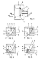
- the device according to the invention of the first embodiment consists of a bolt 11, which is designed as a T-shaped double hook, and a counter-holder 14, which has the shape of a pocket.
- the counter-holder 14 has a bar 15 divided in the middle, behind which the double hook engages in the closed position.
- Lugs 16 are provided on the side of the T-bar of the double hook 11 and come into contact with their contact surfaces 12 on contact surfaces 13 of the counter-holder 14 when the closure is opened, if there is pressure on the side wall from the inside.
- a complete opening of the lock is only possible in such a case if the side wall is relieved of the internal pressure and brought into its completely vertical position, since then the contact surfaces 12 and 13 move past one another when the latch is extended into the open position. So that a bolt lock provided with this bolt has a recovery capability, it has ramp surfaces 17 and 19, which correspond to ramp surfaces 17 and 20 on the counter-holder 14. Between the run-up surfaces 18 and 20 there is a step on the counter-holder 14 in which the contact surface 13 is located. This level is responsible for the fact that when there is internal pressure on the drop side when the lock is opened, the drop side clearly falls outwards, so that the inside pressure is recognized immediately.
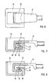
- the device according to the invention of the second embodiment has a bolt which is designed as a double-angled hook bolt 21. In the closed position, it engages with its free end behind a bar 25 of a counter-holder 24, which is also designed as a pocket.
- the contact surface 23 on the counter-holder 24 lies between the two parts 28 and 30 of a run-up surface, to which a run-up surface 27 on the hook 21 corresponds.
- the contact surface 23 lies in one Step between the two parts 28 and 30 of the ramp surface. The operation is the same as that of the first embodiment.
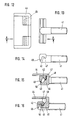
- the device according to the invention of the third embodiment has a slide bolt 31 which, in the closed position, is inserted into an opening 35 of a counter-holder 34, which here consists of a stanchion.
- the latch has an abutment surface 32, which comes into contact with internal pressure against the side wall in the course of the opening process with a surface serving as abutment surface 33 behind the opening 34 of the stanchion 35.
- the contact surface 32 on the bolt 31 lies between the two parts 37 and 39 of the ramp surface.
- the mode of operation corresponds to that of the second and third embodiments.
- the device of the fourth embodiment according to the invention has a T-shaped hook bolt 41 and a counter-holder 44, which has the shape of a pocket.
- the counter-holder 44 has a bar 45 divided in the middle, behind which the hook bolt engages in the closed position.
- the bolt 41 has a run-up surface consisting of two parts 47, 49 separated by a step, a contact surface 42 being located in the step.
- the counter-holder 44 has a run-up surface consisting of two parts 48, 50 separated by a step, a contact surface 43 being located in the step.
- the mode of operation is readily apparent and corresponds to that of the three other embodiments.
Landscapes
- Engineering & Computer Science (AREA)
- Mechanical Engineering (AREA)
- Lock And Its Accessories (AREA)
- Fittings On The Vehicle Exterior For Carrying Loads, And Devices For Holding Or Mounting Articles (AREA)
- Pressure Vessels And Lids Thereof (AREA)
- Hinges (AREA)
- Bag Frames (AREA)
- Vehicle Step Arrangements And Article Storage (AREA)
- Gears, Cams (AREA)
- Seats For Vehicles (AREA)
- Mutual Connection Of Rods And Tubes (AREA)
- Connection Of Plates (AREA)
- Clamps And Clips (AREA)
Priority Applications (1)
| Application Number | Priority Date | Filing Date | Title |
|---|---|---|---|
| AT90125628T ATE85566T1 (de) | 1990-05-21 | 1990-12-28 | Riegel und gegenhalter eines riegelverschlusses fuer abklappbare bordwaende von lastfahrzeugen. |
Applications Claiming Priority (2)
| Application Number | Priority Date | Filing Date | Title |
|---|---|---|---|
| DE9005764U | 1990-05-21 | ||
| DE9005764U DE9005764U1 (de) | 1990-05-21 | 1990-05-21 | Riegel und Gegenhalter eines Riegelverschlusses für abklappbare Bordwände von Lastfahrzeugen |
Publications (3)
| Publication Number | Publication Date |
|---|---|
| EP0457972A1 true EP0457972A1 (fr) | 1991-11-27 |
| EP0457972B1 EP0457972B1 (fr) | 1993-02-10 |
| EP0457972B2 EP0457972B2 (fr) | 1996-11-13 |
Family
ID=6853984
Family Applications (1)
| Application Number | Title | Priority Date | Filing Date |
|---|---|---|---|
| EP90125628A Expired - Lifetime EP0457972B2 (fr) | 1990-05-21 | 1990-12-28 | Verrou et contre-butée d'une fermeture pour ridelles à bascule de camions |
Country Status (6)
| Country | Link |
|---|---|
| EP (1) | EP0457972B2 (fr) |
| AT (1) | ATE85566T1 (fr) |
| CZ (1) | CZ279117B6 (fr) |
| DE (2) | DE9005764U1 (fr) |
| ES (1) | ES2038033T5 (fr) |
| HU (1) | HU214722B (fr) |
Cited By (1)
| Publication number | Priority date | Publication date | Assignee | Title |
|---|---|---|---|---|
| WO2002034611A1 (fr) * | 2000-10-26 | 2002-05-02 | Rosen Goran | Dispositif de verrouillage sur volet de chargement |
Families Citing this family (1)
| Publication number | Priority date | Publication date | Assignee | Title |
|---|---|---|---|---|
| DE9109211U1 (de) * | 1991-07-25 | 1991-11-21 | Karl Hildebrand GmbH, 4006 Erkrath | Riegelverschluß |
Citations (3)
| Publication number | Priority date | Publication date | Assignee | Title |
|---|---|---|---|---|
| DE1678155C (de) * | 1972-09-14 | F. Hesterberg & Söhne, 5828 Ennepetal-Milspe | Riegelverschluß für Wände, Türen, Klappen von Fahrzeugen für den Gütertransport | |
| DE3717310C1 (en) * | 1987-05-22 | 1988-09-01 | Wilhelm Eudenbach | Bolt lock |
| DE3817220C1 (en) * | 1988-05-20 | 1989-10-19 | Wilhelm 5650 Solingen De Eudenbach | Bolt lock |
Family Cites Families (1)
| Publication number | Priority date | Publication date | Assignee | Title |
|---|---|---|---|---|
| GB774224A (en) * | 1954-12-11 | 1957-05-08 | John Perks & Son Forgings Ltd | Improvements relating to fastening devices for hinged drop-sides or tail-boards of vehicles, or for other hinged parts |
-
1990
- 1990-05-21 DE DE9005764U patent/DE9005764U1/de not_active Expired - Lifetime
- 1990-12-28 EP EP90125628A patent/EP0457972B2/fr not_active Expired - Lifetime
- 1990-12-28 ES ES90125628T patent/ES2038033T5/es not_active Expired - Lifetime
- 1990-12-28 AT AT90125628T patent/ATE85566T1/de not_active IP Right Cessation
- 1990-12-28 DE DE9090125628T patent/DE59000888D1/de not_active Expired - Lifetime
-
1991
- 1991-05-20 HU HU911680A patent/HU214722B/hu unknown
- 1991-05-20 CZ CS911477A patent/CZ279117B6/cs not_active IP Right Cessation
Patent Citations (3)
| Publication number | Priority date | Publication date | Assignee | Title |
|---|---|---|---|---|
| DE1678155C (de) * | 1972-09-14 | F. Hesterberg & Söhne, 5828 Ennepetal-Milspe | Riegelverschluß für Wände, Türen, Klappen von Fahrzeugen für den Gütertransport | |
| DE3717310C1 (en) * | 1987-05-22 | 1988-09-01 | Wilhelm Eudenbach | Bolt lock |
| DE3817220C1 (en) * | 1988-05-20 | 1989-10-19 | Wilhelm 5650 Solingen De Eudenbach | Bolt lock |
Cited By (1)
| Publication number | Priority date | Publication date | Assignee | Title |
|---|---|---|---|---|
| WO2002034611A1 (fr) * | 2000-10-26 | 2002-05-02 | Rosen Goran | Dispositif de verrouillage sur volet de chargement |
Also Published As
| Publication number | Publication date |
|---|---|
| EP0457972B2 (fr) | 1996-11-13 |
| ES2038033T3 (es) | 1993-07-01 |
| DE59000888D1 (de) | 1993-03-25 |
| HUT61699A (en) | 1993-03-01 |
| CZ279117B6 (cs) | 1995-01-18 |
| ATE85566T1 (de) | 1993-02-15 |
| HU214722B (hu) | 1998-05-28 |
| EP0457972B1 (fr) | 1993-02-10 |
| ES2038033T5 (es) | 1997-04-01 |
| DE9005764U1 (de) | 1990-09-06 |
| CS9101477A2 (en) | 1991-12-17 |
| HU911680D0 (en) | 1991-11-28 |
Similar Documents
| Publication | Publication Date | Title |
|---|---|---|
| DE69934527T2 (de) | Verriegelungseinrichtung an Seitenwänden | |
| DE69709215T2 (de) | Vorrichtung zur Unterstützung für eine Schiebetür | |
| DE69605148T2 (de) | Aufprallenergieabsorbierende Struktur in einer Fahrzeug-Sicherheitsgurtvorrichtung | |
| DE2412500C3 (de) | Spannverschluß | |
| DE2348998A1 (de) | Tuerentriegelung, insbesondere fuer notausgaenge | |
| EP0692408A2 (fr) | Store ou dispositif cache-bagages pour un coffre de véhicule automobile | |
| DE3734993A1 (de) | Verschlussband aus kunststoff | |
| EP1063379B1 (fr) | Charnière | |
| DE3214092C2 (fr) | ||
| DE102016115215A1 (de) | Seitenwandanordnung für einen Behälter sowie Verfahren zu dessen Herstellung und Behälter mit einer solchen Seitenwandanordnung | |
| EP0457972B1 (fr) | Verrou et contre-butée d'une fermeture pour ridelles à bascule de camions | |
| EP1325995B1 (fr) | Dispositif de sécurité interdisant l'ouverture simultanée, notamment pour armoires à tiroirs | |
| DE69302905T2 (de) | Vorrichtung zum schliessen von beuteln oder dergleichen und sicherheitssiegel | |
| EP0066297A1 (fr) | Dispositif de verrouillage pour portes, volets ou analogues de véhicules de transport | |
| DE4216277C2 (de) | Dekompressionspaneel für Zwischenwände und -böden von Passagier- und Frachträumen in Flugzeugen | |
| DE9319919U1 (de) | Vorrichtung zur Fixierung von Ladegut | |
| DE69707199T2 (de) | Dokumentenhalter | |
| DE29505138U1 (de) | Bandseitensicherung für Türflügel | |
| DE2647669A1 (de) | Verschluss fuer handkoffer u.dgl. | |
| DE3422926C2 (de) | Kugelpfanne für ein Winkelkugelgelenk | |
| AT394838B (de) | Deckel mit kindersicherung | |
| DE19511059C2 (de) | Einbruchsichere Profileinheit, bestehend aus zwei Profilen | |
| DE2716825C2 (de) | Kabelplombe | |
| DE4314884C2 (de) | Vorrichtung zum Abdecken des scharnierseitigen Spaltes von Türen, Fenstern und dergleichen | |
| DE4005311C2 (fr) |
Legal Events
| Date | Code | Title | Description |
|---|---|---|---|
| PUAI | Public reference made under article 153(3) epc to a published international application that has entered the european phase |
Free format text: ORIGINAL CODE: 0009012 |
|
| AK | Designated contracting states |
Kind code of ref document: A1 Designated state(s): AT BE CH DE ES FR GB IT LI NL SE |
|
| 17P | Request for examination filed |
Effective date: 19911217 |
|
| 17Q | First examination report despatched |
Effective date: 19920623 |
|
| GRAA | (expected) grant |
Free format text: ORIGINAL CODE: 0009210 |
|
| AK | Designated contracting states |
Kind code of ref document: B1 Designated state(s): AT BE CH DE ES FR GB IT LI NL SE |
|
| REF | Corresponds to: |
Ref document number: 85566 Country of ref document: AT Date of ref document: 19930215 Kind code of ref document: T |
|
| ET | Fr: translation filed | ||
| GBT | Gb: translation of ep patent filed (gb section 77(6)(a)/1977) |
Effective date: 19930222 |
|
| REF | Corresponds to: |
Ref document number: 59000888 Country of ref document: DE Date of ref document: 19930325 |
|
| ITF | It: translation for a ep patent filed | ||
| REG | Reference to a national code |
Ref country code: ES Ref legal event code: FG2A Ref document number: 2038033 Country of ref document: ES Kind code of ref document: T3 |
|
| PLBI | Opposition filed |
Free format text: ORIGINAL CODE: 0009260 |
|
| 26 | Opposition filed |
Opponent name: PESCA ENGINEERING LIMITED, OF HIGHFIELD ROAD INDUS Effective date: 19931109 |
|
| NLR1 | Nl: opposition has been filed with the epo |
Opponent name: PESCA ENGINEERING LIMITED, OF HIGHFIELD ROAD INDUS |
|
| PG25 | Lapsed in a contracting state [announced via postgrant information from national office to epo] |
Ref country code: NL Effective date: 19940701 |
|
| NLV4 | Nl: lapsed or anulled due to non-payment of the annual fee | ||
| EAL | Se: european patent in force in sweden |
Ref document number: 90125628.9 |
|
| APAC | Appeal dossier modified |
Free format text: ORIGINAL CODE: EPIDOS NOAPO |
|
| PLAW | Interlocutory decision in opposition |
Free format text: ORIGINAL CODE: EPIDOS IDOP |
|
| PUAH | Patent maintained in amended form |
Free format text: ORIGINAL CODE: 0009272 |
|
| STAA | Information on the status of an ep patent application or granted ep patent |
Free format text: STATUS: PATENT MAINTAINED AS AMENDED |
|
| 27A | Patent maintained in amended form |
Effective date: 19961113 |
|
| AK | Designated contracting states |
Kind code of ref document: B2 Designated state(s): AT BE CH DE ES FR GB IT LI NL SE |
|
| REG | Reference to a national code |
Ref country code: CH Ref legal event code: AEN Free format text: AUFRECHTERHALTUNG DES PATENTES IN GEAENDERTER FORM |
|
| ITF | It: translation for a ep patent filed | ||
| ET3 | Fr: translation filed ** decision concerning opposition | ||
| GBTA | Gb: translation of amended ep patent filed (gb section 77(6)(b)/1977) |
Effective date: 19961204 |
|
| REG | Reference to a national code |
Ref country code: ES Ref legal event code: DC2A Kind code of ref document: T5 Effective date: 19970213 |
|
| PGFP | Annual fee paid to national office [announced via postgrant information from national office to epo] |
Ref country code: CH Payment date: 20001120 Year of fee payment: 11 |
|
| PGFP | Annual fee paid to national office [announced via postgrant information from national office to epo] |
Ref country code: BE Payment date: 20001130 Year of fee payment: 11 |
|
| PGFP | Annual fee paid to national office [announced via postgrant information from national office to epo] |
Ref country code: SE Payment date: 20001204 Year of fee payment: 11 |
|
| PG25 | Lapsed in a contracting state [announced via postgrant information from national office to epo] |
Ref country code: SE Free format text: LAPSE BECAUSE OF NON-PAYMENT OF DUE FEES Effective date: 20011229 |
|
| PG25 | Lapsed in a contracting state [announced via postgrant information from national office to epo] |
Ref country code: BE Free format text: LAPSE BECAUSE OF NON-PAYMENT OF DUE FEES Effective date: 20011231 Ref country code: LI Free format text: LAPSE BECAUSE OF NON-PAYMENT OF DUE FEES Effective date: 20011231 Ref country code: CH Free format text: LAPSE BECAUSE OF NON-PAYMENT OF DUE FEES Effective date: 20011231 |
|
| REG | Reference to a national code |
Ref country code: GB Ref legal event code: IF02 |
|
| BERE | Be: lapsed |
Owner name: F. HESTERBERG & SOHNE G.M.B.H. & CO. K.G. Effective date: 20011231 |
|
| EUG | Se: european patent has lapsed |
Ref document number: 90125628.9 |
|
| REG | Reference to a national code |
Ref country code: CH Ref legal event code: PL |
|
| APAH | Appeal reference modified |
Free format text: ORIGINAL CODE: EPIDOSCREFNO |
|
| PGFP | Annual fee paid to national office [announced via postgrant information from national office to epo] |
Ref country code: AT Payment date: 20091217 Year of fee payment: 20 Ref country code: ES Payment date: 20091218 Year of fee payment: 20 |
|
| PGFP | Annual fee paid to national office [announced via postgrant information from national office to epo] |
Ref country code: FR Payment date: 20100105 Year of fee payment: 20 Ref country code: GB Payment date: 20091221 Year of fee payment: 20 Ref country code: IT Payment date: 20091224 Year of fee payment: 20 |
|
| PGFP | Annual fee paid to national office [announced via postgrant information from national office to epo] |
Ref country code: DE Payment date: 20100111 Year of fee payment: 20 |
|
| REG | Reference to a national code |
Ref country code: GB Ref legal event code: PE20 Expiry date: 20101227 |
|
| PG25 | Lapsed in a contracting state [announced via postgrant information from national office to epo] |
Ref country code: GB Free format text: LAPSE BECAUSE OF EXPIRATION OF PROTECTION Effective date: 20101227 |
|
| REG | Reference to a national code |
Ref country code: ES Ref legal event code: FD2A Effective date: 20120305 |
|
| PG25 | Lapsed in a contracting state [announced via postgrant information from national office to epo] |
Ref country code: ES Free format text: LAPSE BECAUSE OF EXPIRATION OF PROTECTION Effective date: 20101229 |
|
| PG25 | Lapsed in a contracting state [announced via postgrant information from national office to epo] |
Ref country code: DE Free format text: LAPSE BECAUSE OF EXPIRATION OF PROTECTION Effective date: 20101228 |